|
|
The curious thing about specifications is that there are none for musicality. I love the single-ended tube builders who stick to their guns about the musicality of Class A amps that run into single-dig it distortion. Musicality must be paramount! The first specification I always place a few notches down on the criteria list is distortion. Quite frankly, no one on the planet can hear the difference between 0.01 and 0.005 distortion. In fact, once you get under about 0.5%, if that, distortion is a non sequitur. What really counts to my ears is tracking, which I pay close attention to when I begin the design process. I always go for high slew rates because they bring clarity and definition to amps. A hat goes off to designers such as MOON who list slew rates in their specs.
 Photo 1: The Willowhill pre-amp
Willowhill is just that type of project (see Photo 1). The PMBF4393 JFET has a rise time of 5 V/ns (200 V/µs), and the people who have listened to this amp can hear the difference. I built it as a compan ion to my 5002 power amp, both using the HA5002 buffer.
What's wrong with op-amps, anyway?
Op-amps are slow (see Figure 1), most run 5 or 6 V/µs. Even the highly touted OPA627 (blue trace) at 40 V/µs and 50 times the cost of the 4393 can't beat it (see Figure 2).
The other thing about JFETs is their character. They clip like tubes, and I love tube distortion. Let's face it, we all love distortion. We're just picky about what kind!
Figure 1: The PMBF4393 vs. the OPA-627
Design philosophy
My goals with this amp were musicality, definition, and clarity. I wanted an amp that could give equal justice to large orchestrations, solo guitars, and the golden voices that fill a good part of my listening time. I played with several factors and pushed limits to see whether my "what if " theoretical ideas would make a difference empirically. They did, at least to these old ears, and after many SPICE hours, prototypes, and tweaks, this amp emerged. In fact, please look at this amp as modules from the power supply, input/output, gain stage to the anti-pop circuitry. You can build each independently or modify them to fit your specific interests.
I designed the power supply (see Figure 3) for a single toroidal transformer with a dual 18-V secondary. I isolated the power to each 38-V JFET using one secondary for both, doubling it and tapping off the 18-V point for the positive side of the HA5002 buffers that run ±18 V (IC2, IC4).
The input/output board (see Figure 4) is designed for zero open contacts and to be highly ergonomic. This is no small design requisite. Ergonomics play an important part of my designs because I'm always turning pots and changing input channels. This amp sits at my work desk, and I flip between my CD player, FM tuner, and live stream-constantly!

Figure 2: Top trace Agilent 33220A, bottom trace OPA227
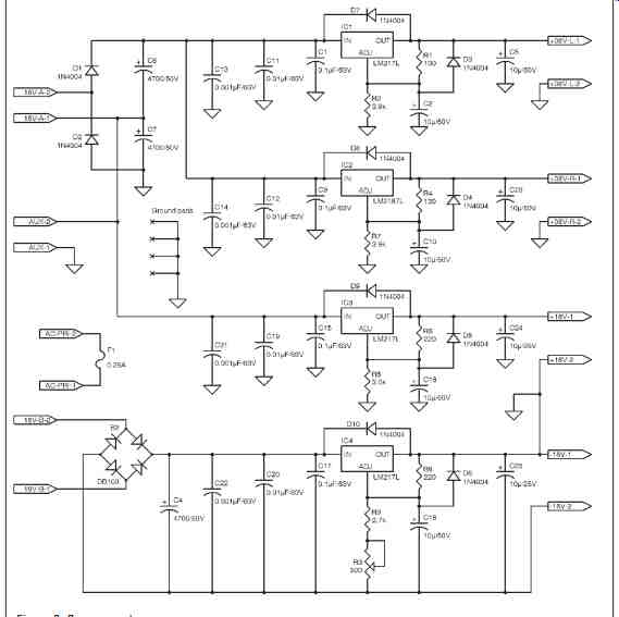
Figure 3: Power supply

Figure 4: In-out

Figure 5: Gain stage
What's special about this input/output is the optical encoder used to change from one input to the next. No contacts brush each other in the encoder, and its mean time between failures (MTBF) is extremely high. You can spin the dial all day and it won't wear out. It will never be noisy and never need to be cleaned. It runs four relays-one for each input- and one relay covers both the left and right channel. The relays are hermetically sealed, run on only 6 mA, have a MTBF in the millions, and cost under $4 each.
Another thing I don't like is printing on faceplates. Call me finicky, but lettering wears out over time and it's hard to read, especially in low light. Instead, I employed four different color LEDs, one for each input; changing from one input to the next lights a specific LED that sits behind the input knob. I used a black Lexan face on the amp and inserted a clear Lexan disk behind it. As I change from one input to the next, the white knob and clear Lexan background change color. Not only is it neat, but I can change which input I'm listening to in a completely dark room.
The gain board (see Figure 5) uses a PMBF4393 JFET running Class A and two HA5002 buffers from Burr-Brown/ Intersil. I'd like to talk a little about buffers and how I use them in amps.
Buffer Benefits A good buffer such as the 5002 adds little, if any, coloration to the music. It's basically a transconductance device that gives great latitude and simplicity in connecting the JFET or tube. Yes, that's correct, I said tube because I use buffers to connect tube stages. You can also use the buffer to bias a tube or FET simply by biasing it just as I have done in this circuit.
Here I use zero bias, but it is an easy task to turn a bias pot and in effect change a tube's bias.
Another benefit of buffers is their ability to place very high impedances on in puts and very low impedances on outputs.
I don't like transformers in my circuits (to each his own), and buffers mean I don't have to use them. Capacitors are another story. They are a necessary evil but, like most of you, I have specific ideas about how I use them in circuits. I like to keep their values as low as possible. You will notice that the capacitors in this project are 0.1 µF.
Say you have an input impedance to your buffer that is 470k, which is close to the actual value in this circuit. The band width lead is: You could have used a 0.47 µF capacitor with an input impedance of 100k, which would give the same lead frequency, but I specifically wanted to keep the input capacitances low just to see how, if at all, it would affect the sound. The 0.47 µF capacitor 100-k resistor input has another benefit in that it reduces input noise, but this amp is very quiet and I especially like the sound so, for now, the 0.1 µF-capacitor stays.
If you have long input runs, you might want to consider using the 0.47 µF/100 kOhm option, but even with long runs I didn't have a problem. This is certainly an option, and I suggest you find your own answers. You will also notice that I didn't use an input capacitor before the first op amp; you can if you like, especially if you have problem outputs from your external components. Remember that any bias on the input of the 5002 reflects on the output. The output is 3 ohm, so it is very convincing.
You cannot, however, eliminate the first 5002 without increasing the value of the volume pot. Here's another area where I like to keep things low. The pot for this amp is 10 kOhm--much too low for even a 0.47-µF input capacitor.
Lag (output frequency falloff ) also benefits from the buffers. What I have done is place very little load on the JFET. It's just in the circuit for amplification; the buffers do all the rest of the work, and nicely. With 1300 V/µs rise time the 5002 slows nothing down in this high tracking amp.
One more thing: don't be tempted to use a through-hole PN4393 in place of the SMD PMBF4393. It tops out at 30 V and not 40 like the latter.
The anti-pop circuit is designed to catch any pops when the amp comes on (IC4a) as well as when it's turned off. It senses the slow drop of charged capacitors when shutting down and shuts the relay down quickly. It also gives the circuit a few seconds delay when powering up. It acts as an "and" gate because both conditions must be true-IC4a must be low and IC4b must be high for an output signal. One half the comparator controls turn on and the other turn off.
CONSTRUCTION
Boy, did I goof ! If you look at my lay out you'll see that I thought I could get away with the power transformer close to the digital pot I employed here. I couldn't, and I paid the price for noise-not bad, but why have it if you can avoid it? Actually, I like dedicated cases for my power supplies and power circuits so you might want to explore that avenue.
As I previously stated, think of this as a module project: you can use your own input stage volume stage (as I did here) or even power supply. As for the amp board, I built it before I did any drastic modding, but this is an open amp and I'd love to hear about everyone's ideas and tweaks! Adjust all the pots for a null (zero volts) on pin 8 of all the 5002 buffers.
This is an easy task, so do it a couple of times. Bias isn't that critical-as long as you're within ±50 mV things will be fine, although I easily got my circuits down to only a few millivolts.
Before inserting the ICs in their sockets (if you use sockets), check pins 1 and 7 for +18 V and pins 2 and 5 for -18 V. While the price of the 5002 is not prohibitive, there is no reason to blow chips! I did add a headphone socket. This is your option, as are the screw terminals.
They make it handy to troubleshoot prototypes, but they do encourage noise later on down the road.
The circuit boards (see Photo 2) are straightforward, and while I did use SMDs on the input board, I tried to avoid them on the gain board by utilizing as many through-hole devices as possible.
Finally, give this amp some time to break in-at least 50 to 100 hours. I have included a subwoofer output. My favorite configuration is a two-way speaker with a sub.
I favor building nice cases-do it right. Nothing looks worse than a great amp in a tin box. It's like washing your car-it always seems to run better after it's washed!

Photo 2: Circuit view
====
SPECIFICATIONS
• Gain 21.58 (12/1)
• Bandwidth: Less than 4 Hz to greater than 500 kHz
• Distortion & noise: Less than 0.2% (200 mVPP input)
• Input impedance Greater than 500 kOhm
• Output impedance: ~3 Ohm
• Inputs 4 (optically driven sealed relays)
Test instruments:
• Agilent 33220A AWG generator
• HP 334A Distortion analyzer
• Agilent 34410A Digital meter
• Tektronix TDS2012B Digital scope
• HP6632B Power supply
• Array 3710A DC load
====