|
|
This high-quality vacuum tube phono preamp features a "brick wall" that RF interference cannot penetrate.
This phono amplifier has the most realistic sound reproduction of any of my phono amplifier designs. All my earlier phono amps avoided the use of negative feedback; this amplifier uses 6dB of feedback in the third stage. Applying feedback to this stage reduced the 1.5% distortion caused by the RIAA network to 0.66%. It simultaneously enhanced the realism of the sound. The improvement is outstanding! This phono amplifier required as its main objective the ability to reject interference from cell phone, TV, FM, AM, police, fire transmitter station located within three-fourths of a mile, and five cell phone transmitters as close as 400-ohm. To achieve this degree of rejection, I modified the RIAA circuit architecture to successfully reject the RF signals. This modification is applicable to all traditional RIAA circuits and is mentioned as a modification in my articles published. The reason for this change is that I moved to the top 19th floor of a high rise and am surrounded by transmitting antennas at this location.

With a voltmeter hooked to the output of the phono amp, the pointer/ signal was very active (not audible) and looked like a studio audio dB meter. With the modification of the RIAA circuit, the voltmeter pointer is stationary at zero. This feature is a real improvement for phono amplifiers and is very easy to implement. More details on this modification appear later in this article.
This phono amplifier offers "life like" concert hall performance for a modest cost of $130. It is a design featuring high-perveance tubes in the phono and line amplifier. The phono amplifier features three 6922s. It has an output voltage of 0.46V RMS (line amp) or 0.4V RMS (cathode follower) with an input voltage of 3mV/1kHz. Note that the phono amplifier in this article does not use high-mu 12AX7s, but instead uses linear, low noise, high-perveance 6922s with a mu of 33.

TABLE 1 Distortion Measurements of Phono Amplifier at 1V Output
Noise and Gain Measurement: The noise of the phono amplifier is circa 3.5mV at the output of the cathode follower stage with the input of the first stage 6922 open.

FIG. 1: Phono amplifier.
During the early days of the introduction of magnetic phono cartridges in commercial radios, the 12AX7s were developed to eliminate a medium mu tube and thus save the radio manufacturers money. The implementation of the 12AX7 was based on cost constraints and not technical excellence. Many manufacturers who employ the 12AX7 for costly hi-fi use do not seem to be aware that they adapted a low-cost concept in their product. To provide technical excellence in phono amplifier design and ensure a superior sound, vacuum tube phono amplifiers should be limited to tubes with a mu of circa 40. All low noise preamplifier tubes are designed with heaters having low heater current.
LINE AMPLIFIER AND CATHODE FOLLOWER
The line amplifier (Fig. 1) uses one 6922 with a mu of 33. The 6922 has a flat frequency response of 20Hz to 20kHz and a distortion of less than 0.1% from 20Hz to 20kHz at 1.0V RMS. The 6922 voltage gain is 15 and output impedance is 5500-ohm. The plate voltage via 39k resistor is 95V DC and the cathode voltage via 820 ohm resistor is 2.7V DC. The line amplifier stage employs 6dB of negative feedback via 220k resistor and 10nF capacitor. I chose the value of the capacitor so it does not affect the low-frequency rolloff of the RIAA network. See Table 1 for distortion measurements.
The cathode follower is a 5687 with a mu of 16 but has no gain in a cathode follower configuration. The frequency response is flat from 10Hz to 100kHz and distortion is 0.2% at 1V RMS. The plate voltage is 235V DC and the cathode voltage is 12V DC via a 2700 ohm resistor. The low output impedance of the cathode follower permits you to run a long audio cable to the power amplifier.
The cathode follower is only required when you use a long run audio cable.
VACUUM TUBE PHONO AMPLIFIER
The phono amplifier uses two 6922s in a non-feedback design with a passive RIAA network. The noise is circa 3.5mV and sensitivity is 3mV for 0.46V RMS (line amp) or 0.4V RMS (cathode follower) at 1kHz. The distortion of the first, second, and third stage is less than 0.15% from 20Hz to 20kHz with a 0.5V RMS output in each of these stages. These distortion measurements are made bypassing the RIAA circuit which produces 1.5% distortion.
The 6922 third stage employs 6dB of feedback and reduces the distortion to 0.66%. I chose the 6922s for their low noise capability.
The first stage 6922 has Ebb of 220V DC, Eb of 55V DC, and Ek of 1.2V DC. The second stage 6922 has Ebb of 224V DC, Eb of 100V DC, and Ek of 2.6V DC.
With 3mV, 1kHz fed to the input of V1, the output at V1 should indicate 55mV. The loss through the RIAA net work drops the 55mV to 4.8mV at the input of V2. The voltage at the output of V2 is 38mV. The 38mV output of V2 feeds the third stage V3 and the output of V3 is 0.46V RMS. The output of the cathode follower is 0.4V RMS.
Capacitor C1 tailors the high frequency output of the magnetic pickup, and R1 provides the proper load to the cartridge.
=======

TABLE 2: RIAA Frequency Response of Phono Amplifier
Note: The output voltage of the audio signal generator is set for circa 75mV RMS with a 1kHz signal to obtain an output from the cathode follower of 1.0V RMS at 1kHz. The output signal level of the audio signal generator is not changed for the remainder of the frequency measurements.
========
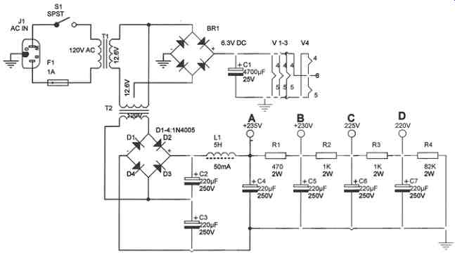
FIG. 2: Power supply schematic.
The value of capacitor C1 is determined from cartridge manufacturers' minimum recommended capacitance value and by subtracting 100pF from that value. The 100pF value represents the 3” cable capacitance of the record player and input capacitance of 6922.
Note 1: I recommend you have an audio oscillator (optional) and vacuum tube voltmeter or DMM. This equipment is essential to ensure proper balance and gain is obtained throughout the phono amplifier circuit. The 6922s provide a very broad frequency response with a detailed and clean output.
Note 2: Accuracy of the RIAA net work is checked against the simulated output of the actual RIAA curve as shown in Table 2.

ABOVE 1: Tube phono amp
RIAA MODIFICATION
The traditional RIAA circuit is modified to reject unwanted RF signals.
This modification establishes a "brick wall" that RF signals cannot penetrate.
The modification is as follows: The 100nF coupling capacitor is moved from the plate of the first stage 6922 to the grid side of the second stage/RIAA network. This produces a carbon block between the plate and the R/C net work. The frequency forming capacitor is split into two segments with a 1nF (0.001µF) capacitor connected to the plate of the first stage 6922 and a 10nF (0.01µF) capacitor connected directly to the grid of the second 6922. Make sure the 1nF and 10nF capacitor leads are short by using solder terminals.
The typical second stage grid resistor of 470K or 1M-ohm is reduced to 220k. This is the extent of the modification and the purpose of the change is self evident. The output of the first stage and the input of the second stage are heavily bypassed for RF signals. Note that the same RIAA frequency curve is now maintained using a 1nF and 10nF capacitor, as opposed to the original design that used a single 12nF capacitor.
POWER SUPPLY
The power supply (Fig. 2) consists of two 120V AC to 12V AC, 3A trans formers, which are connected back-to back. The first transformer has one half of the secondary winding connected to a full-wave, bridge-rectifier.
The output of the rectifier is 6.3V DC and is filtered by a 4,700µF capacitor. The output of the heater sup ply provides 6.3V DC to the three 6922s and one 6587 with a ripple of 0.32V RMS. The 12.6V AC output of transformer T1 is also connected to the 12.6V AC winding of trans former T2. The 110V AC secondary is connected to a full-wave bridge (D1 through D4) rectifier. Voltage doubling is accomplished by capacitors C2 and C3.
The choke L1 diminishes the switching transients that occur during the rectification process. Capacitors C4 through C8 are additional filtering devices and provide a low noise ripple of 0.6V RMS at the 235V DC output (the noise measurement was made with a DMM using shielded test leads). Resistors R1 through R3 provide de-coupling. The resistor R4 is the bleeder for the 235V DC out put. Transformers T1 and T2 are only slightly warm after hours of operating time and cost only $10 apiece.
CONSTRUCTION
It is imperative that the phono amplifier (Photo 1) is an unpainted aluminum chassis to ensure that all components are properly grounded. Do not use a painted steel chassis!
The electrolytic capacitors are grounded at the negative band, except those connected in series. All other components are connected to tube sockets. In the phono amplifier section, seven 5-pin terminal strips are required.
It is very important that the assembly be tailored around the implementation of the seven 5-pin and three 2-pin terminal strips (to ensure a good ground, interconnect the three 2-pin terminal strips ground lug with a separate ground wire). Also required are eight spade lugs. Using the terminal strips provides a very simple step-by-step construction process. It also permits easy changeability of parts. Building the control unit is a fun, easy project using the 5-pin terminal strips and a night mare using a PC board. The RIAA network components are mounted on a single five-pin terminal strip.
It is important all audio runs approximately 3” or more use shielded cable and that the shield is grounded at the input end. The shielded cables at the input end should be grounded at the phono input jack. It will only be necessary to ground the shielded leads of the phono amplifier at the end nearest the input of the amplifier. The 5-conductor shielded cable that connects to the 6-position rotary switch must be grounded at the input end. Most grounds are made to the center post, 5-pin terminal strip. The use of chassis-mounted solder ground lugs for the cathode and grid resistors and heater grounds is also recommended.
The minimum test equipment required for building the phono amplifier and the control unit is a vacuum tube voltmeter or DMM, and an audio signal generator is optional.
USEFUL HINTS
Building a preamp circuit can be very challenging, especially for first-time builders and 82-year-olds like myself. I provide the following useful tips, but I'm sure I missed many.
1. Have a well-lighted area and clean your eyeglasses and keep a magnifying glass nearby.
2. Use 40W pencil iron and 60-40 rosin core solder.
3. Use spade lugs generously when a component or heater ground is needed. Use 5-pin terminal strips for mounting components.
4. Make sure you don't have any cold solder joints and insert components through holes of tube socket pins.
5. Secure fasteners for lugs and terminal strips with a tight fit to ensure a good ground. Do not secure until all components are soldered to avoid a cold solder joint.
6. Tubes V4 and V5 use 2-pin terminal strips for ground and B+ connections. Capacitor C8 of power supply is located at V4, 2-pin terminal strip.
7. Capacitors C4 through C7 and R1 through R3 are secured to a 5-pin terminal strip. The 6.3V DC tube heaters wires and capacitor C1 are connected to a 5-pin terminal strip.
8. At the output of V6 a 5-pin terminal strip is used to secure capacitor C9, B+ and plate resistors and grounds of shielded cable.
9. When construction is finished, make sure all screws and nuts are tightened to ensure good grounding.
An improper solder joint or a defective tube socket with loose sleeves can cause a hum, howl, squeal, or micro phonics. If this occurs, check all fasteners for snugness and discard screws that have stripped threads. Examine all solder joints under a bright light and using a pair of needle nose pliers, tug on all wires and components to ensure the solder joints are secure. This is the area that causes the most trouble when building preamps. Also, ensure components have space between each other and try to keep leads short.
When ordering tubes, you should purchase one extra 6922 and 5687. If an ordered tube is defective, this will simplify troubleshooting.
In conclusion, this phono amplifier has exceptional concert hall life-like sound and has excellent RF rejection capabilities. The line amplifier stage with 6dB of feedback provides realism to the music. This stage brings the music to life. The line amplifier stage is suitable for use with short audio cable runs. For long audio cable runs, be sure to add the cathode follower stage. For $130 and some spare time, this is a project that can be very rewarding. The phono amplifier has been operating for five years with no problems.
===========

Table 3: Phono amplifier parts list (double all parts, except C9-C11, J1-J4,
V1-V4, X1-X4, W1) These 7/8” diameter high-quality ceramic tube sockets provide
sleeves that grasp the tube fins firmly. They are recommended for use with
high gain preamplifier circuits. The cost with shield is $2.25.
Note: These are the best jacks for low noise applications I could find.

Table 4: Power Supply Parts List
PARTS SUPPLIER:
RS = Radio Shack, www.RadioShack.com
AE = Antique Electronic Supply, www.tubesandmore.com
ALEL = All Electronics, www.allelectronics.com
BE = Baynesville Electronics, www.baynesvilleelectronics.com
Mouser, www.mouser.com
TEST EQUIPMENT USED
H-P distortion analyzer, 331A Heathkit sine-wave, square-wave, audio generator, IG-5218 DMM, Radio Shack 22-168A Oscilloscope, Proteck, Model 6502 Warning: Dangerous voltages are present, exercise extreme caution when working on the control unit and never leave the control unit up side down when children are present.
Also see:
These quick DIY phono projects
DIYAudio.com (phono/analog-source forum)
= = = =