.
Parts 1 and 2 covered why you need to clean up a power line and two ways to do it. Here are some additional methods.
One of the most common methods to clean up a powerline is to use an isolation transformer. Unlike an audio transformer, which is designed to have a wide bandwidth, this special kind of transformer is designed for a narrow frequency response.
DESIGN DECISIONS
Transformer design is no longer considered a hot field and is not often offered in schools today. So, of course, my education included a semester of magnetics. I can actually design a transformer that does not catch fire. (Smoke does not count!)
The first area of concern is designing the magnetic core. There are two popular structures: the toroid or continuous tape wound core and the E-I core. The toroid is becoming more popular today because the costs of making them have decreased. There is a bit of debate as to which style is preferred for audio power supplies. I generally find the values I need are offered in only one style, solving that design decision!
Transformers use a coil(s) of wire to produce a magnetic field and then another coil(s) to turn it back into electric current. The ratio of the turns from the primary to the secondary determines the relationship of the input voltage to the output. There is some loss in the process, but it’s usually not of much concern in small transformers.
To confine and allow a greater magnetic field, a core is used. The problem with a core is that at some point the material saturates, just as the toy telegraph did. There are other issues, such as the magnetic field increase is not linear current over most of the useful field range, the core can act as a shorted turn and eat up energy, there is extra inductance in just winding the coils, and, of course, there is also capacitance in each coil and between them.
If a good transformer designer works at it, he/she can adjust the coil windings for a wide or narrow bandwidth. The winding designs can minimize or maximize the inductance and capacitance of the windings.
One of the important considerations for an isolation transformer is the inherent capacitance between the primary and secondary windings of the transformer. There are several techniques to minimize this. The most popular is to wind the primary on the coil form first, place a copper foil shield that is insulated on one side to prevent it from acting as a shorted turn, and then to wind on the secondary. A more recent method is to use a plastic bobbin that winds the coils side by side to minimize the coupling. I have seen some claims that just using a toroid core minimizes coupling.
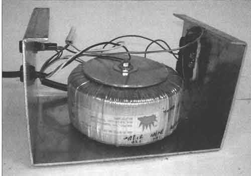
PHOTO 1: Isolation transformer.
The copper foil Faraday shield is found in the transformers of most professional audio gear. However, I rarely find these types of transformers offered for general use.
In addition to placing a shield, with careful design of the windings and core material, the bandwidth of the transformer may be reduced to prevent high- frequency noise from going through.
If, for some strange reason, you need to know a bit more about the design of small transformers for both power and audio use, this topic is briefly covered in the Radiotron Designer’s Hand guide avail able from Old Colony on CD.
CLEANING THE LINE
I could build an isolation transformer. The easiest way is to take an old transformer apart. If you decide to do this completely, be sure to count the number of turns in the primary winding. You will need that number of turns, no matter what size wire you use, to avoid saturating the core. Of course, in a few cases you can save the primary winding and just remove the secondary, making sure to count those turns.
Based on either the primary or secondary windings, you can then figure out how many turns per volt you need to get your desired secondary voltage. Of course, add 10% for winding resistance and core loss. Size your wire for the current you need. The original core size will determine the total volt-amperes the core can handle. You just can’t rewind a 24V 1A transformer for 120V at 5A. 200niA is about all you will get.
If this sounds too much like work, it is. I will sometimes modify a transformer by adding an extra turn or two for an additional secondary. You can use this as a high current winding or place it in series with one of the other windings to adjust the voltage.
I have also wound application-specific transformers for prototypes using a commercial core. For this project I will buy a ready-made transformer, and there are several to choose from.
This transformer can have a small voltage step-up to correct for the flattening of the waveform and the losses in the pre filters and cable. It should be de signed as an isolation transformer, meet the applicable codes and standards, and even be able to do a few more tricks.
Photo 1 is my plain vanilla isolation transformer that lives on my test bench.
To take the idea of AC line improvement a step further, you can use balanced power. Normal AC supplied for residential use actually is balanced power! The normal feed is two lines called the hot wires and, a center tap called the neutral. The neutral wire is grounded, but it’s not used for the safety ground. That is a separate wire connected to the neutral and building ground at one point only in the properly wired home.
When you use a single line to the center tap or neutral, you get your typical 120V AC or half of the balanced 240V that is really provided. The National Electrical Code recognizes that when a line is balanced, noise rejection is improved for audio purposes.
With a center-tapped isolation transformer, you can take the single unbalanced AC line and balance it. The ad vantage of this system is an almost total elimination of hum from musical instrument grade sound equipment. It won’t hurt the better stuff either. I show this circuit ( Fig. 1) with a Plitron transformer made for the purpose. The other part numbers are from Digi-Key.
One big concern with balanced power is that a simple switch on the output will turn off the equipment but may not leave it safe! To fix that, you need a double-pole switch. The other safety issue is to be sure to build this in a metal box. This transformer isolated line cleaner costs a bit more than the resonant filter version.
This circuit ( Fig. 1) can handle 20A. That means that the 3AG style fuse that was fine for the earlier circuit may be too small for this version. A “Midget” fuse is the next size up and will work well here. Check to see whether your outlets are rated for 20A before you build this version. A 20A outlet will take a 15A plug, but a 15A outlet won’t take a 20A plug. A 20A outlet has a T-shaped slot on the hot side jack. A 20A plug has one blade perpendicular to the other.
I show this circuit with a 15A fuse because that is what most outlets provide. If you choose to use this for the full 20A rating of the transformer, you will need a proper plug, fuse, and a higher current input switch.
The case can come from the electrical supply house such as in the earlier version. However, because this circuit will power more devices, you may want to cheat a bit on mounting all the AC out lets. Buy a surface quad box or two with plates and a few box connectors with bushings. Now one or two 5/8” holes will do for all of the wiring.
You now have met a reasonable set of engineering goals. You are getting lots of current, restored the peak voltage, and cleaned up much of the line noise. A good question is “Can you do better?”
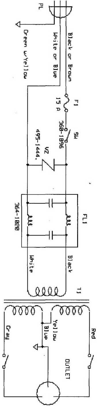
Above: Fig. 1: Isolation transformer circuit.
AC POWER SUPPLY
Yes, you can. So far everything you have done is with passive devices. If you use active devices, you can make the power line appear to have almost no resistance or, in other words, make the line stiffer. I have already mentioned how as the power supplies draw current the voltage drops. When your power amplifier charges the filter capacitors, your AC peak line voltage drops. You can reduce this compression by using a regulated AC power supply.
The simplest method of achieving a regulated AC supply is to hook up a 60Hz oscillator to a very large power amp (one that uses feedback to stabilize its output!) and use it to provide AC mains. You can then set the voltage to whatever you need. Some of the older vacuum tube gear was designed for a line voltage of only 115V, while some modern gear likes 126V. Some gear works better when the supply frequency goes up to 90Hz.
This may seem like a costly and inefficient way to achieve power. It is. For safety reasons, you should start with a power transformer to get the line isolation. Then you will need some large rectifiers. It’s hard to feed capacitor steroids, so you will need some really giant ones.
The output transistors are doable even though you will need at least a dozen. It’s the heatsink that you might want to get three estimates for. Ed Dell supports the principle that amateurs can build professional-quality gear both in appearance and performance and save a bundle doing it. Besides, it’s fun.
However, if you wish to try the high- power regulated AC approach, I suggest you purchase a used Crown MA5000- VZ amplifier, which can easily deliver 20A at 120V if you can feed it properly. These amps were the mainstay of professional sound reinforcement for many years and are now being replaced by even bigger Crown amps. So as an amateur you have a rare chance to take advantage of the professionals’ need for “new, bigger, and shinier.” Of course, if price is no object you could buy the brand new version, the MA5002VZ.
Just put the amplifier in the mono bridging mode and connect your outlets to the two red terminals. Don’t forget to fuse this line! Crown would like you to put a very large capacitor resistor network in series with the line to keep the amp happy under worst-case inductive failures. That is your call. Be sure to check the voltage and frequency before you connect your gear! You may even wish to keep a monitor on the output all the time. If you have a problem, check the VZ switches hidden under the front air filter.
Of course, you can still build the oscillator to task the MA5000VZ.
You could filter the incoming 60Hz line and use that for the reference. One difficulty is that even after cleaning up the noise and distortion the voltage is not constant. You also would need to add some sort of variable gain amplifier (VGA) after the filter. The VGA is adjusted by comparing a reference voltage to the actual output to make sure that as the incoming AC line varies due to changing loads and the whims of the electric company, the supply does not. This could be made to work, but seems complicated.
You could build a classic Wien-bridge oscillator, but this introduces the problem of settling time, and the output voltage is still not regulated.
If you thought to use a phase locked loop, that also would work. A simple oscillator is compared to the zero crossings of the AC line and sped up or slowed down to match. Some sort of lock out would be needed while the oscillator locked on to prevent really strange things from happening. Also, a level control would again be needed for the output reference.
Another choice is a microprocessor feeding a D-A converter to produce a sine wave. Very do-able. Although the hardware would include just a few chips, much software would be required. . . and more work than I like to do.
Of course, it’s even simpler to just have a microprocessor output line drive an RC low-pass filter, but I prefer to use a weirder type of circuit—a square- wave oscillator feeding a transversal filter! Sounds like a digital analog circuit! Actually, it’s a discrete time continuous voltage device.
A 555C timer is the clock for the entire system. I chose a 64 stage filter. Because my filter works on essentially half of the sine wave, the clock needs to be 128 times faster than the output signal. This is 7680Hz for a 60Hz output. I have added a variable resistor so that you can try output frequencies from 50 to 90Hz.
The clock signal tells my discrete time delay line when to shift the data, which is just the clock signal divided by 128. Either it’s high (5V) or low (0V). The input signal is a square wave whose level is very stable. I use a common in expensive counter IC—type CD4020— to give me my data signal.
This square wave feeds the 64-step delay line, which is made up of eight 74HC164N serial-in parallel-out shift registers. CMOS process logic tends to have very nicely controlled output impedances for this use while using almost no power.
FILTER OPERATION
At first, all of the outputs are low, giving zero volts out. Then at the next clock cycle the first output goes high to 5V. The rest stay at zero. The first resistor causes the output to move up a bit. Then at the next clock cycle outputs 1 and 2 are high, giving a greater output. This continues until all the outputs are high and the peak of the sine wave is reached. The output 1 goes low, starting the downward journey.
Selecting the right resistor values gives me a good approximation of a sine wave. Note that the voltage reference is the actual power supply voltage. Here I use common 7805 type regulators, which, by themselves, are actually not quite as accurate as they could be. By using a regulated 12V source to feed the regulator, the double regulation seems to be adequate. The actual regulation seems to vary depending on who makes the regulator chip.
If you use all CMOS logic devices, the current draw is so small most of the current is used by the regulator chip. For the 12V regulators I use a classic shunt regulator in the simplest form. A resistor and zener diode give me more than adequate regulation, and the cost is minimal.
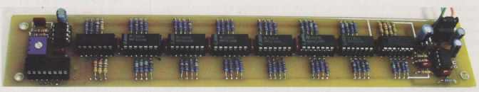
PHOTO 2: Circuit board.
The classic transversal filter works by multiplying each output by a carefully calculated constant to produce a filter. In this case I want a filter that will give me a sine wave.
I am able to calculate what the constant is for each filter tap to get the desired waveform. If you wanted a universal filter, you would use an analog multiplier for each tap. I just use a resistor because the tap values never change. I only want one filter result!
A large resistor is the same as multiplying by a very small number and a small resistor approaches multiplying by 1. Just be sure to include the resistance internal to the shift register chip when picking resistor values. I find keeping the values above 10 k-Ohm reduces this effect.
Because the resistor values are with in only 1%, it seems reasonable to use around 100 steps for the filter. 128 is a good binary choice and easiest to implement.
The results of all of these multiples are summed to form the correct value (voltage) by a single op amp. The result should be a sine wave of 60Hz made up of 128 segments.
PARTS LIST
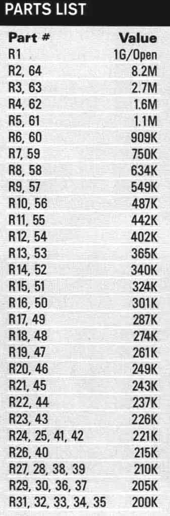
The distortion of this waveform will be mostly determined by the lack of ac curacy in my multiplier. In other words, the resistors’ tolerance determines the distortion. Using 1% resistors for the values under 1MQ and paralleling them reduces the individual contribution to the total error. I would expect this distortion to be less than .25% for the values used here. A simple low-pass filter in the feedback of the op amp set at about 600Hz should ensure this distortion can be lower.
Figure 2 is the actual output of this oscillator. I am not sure whether the digital artifacts are due to the signal or the digital scopes’ resolution.
The same filter taps are used for both the positive- and negative-going excursions of the waveform; as a result, the even-order harmonics are very effectively cancelled. As shown here ( Fig. 3), the second-order product is almost 95dB down. The highest distortion product is the third harmonic, which is down by 55dB. This is a distortion of .18%. There is also a bit of clock noise that comes through, but it’s even lower. You could add a filter to lower this, but I wouldn’t bother.
The filter on the output op amp ( Fig. 4) causes the voltage to drop by 1% at 90Hz. I used a golden oldie for the op amp: an LM301. I chose it because it uses external compensation, which allows me to reduce the bandwidth to decrease noise and distortion.
You could place this circuit in a small box, or even on a small circuit card and insert it into the space provided in an MA5000VZ amplifier. The current draw is low enough that it could be powered by the amp’s internal power supply. I built it on a small PC card.
No power supply is shown because the amplifier usually can provide the power. It requires ±15 to 24V at 15A.
You can, of course, also use this basic design for a wide range swept oscillator. With different tap values, it can produce other waveforms. A cute modification is to use the shift registers as a pseudorandom counter and adjust the taps for a pink noise filter.
If using a monstrous amplifier and oscillator seems like overkill, it is. Perhaps as a more modest approach you can use a smaller amp with a step- up transformer to provide a clean AC source but at a lower total power level.
I will look at that option in part 4.
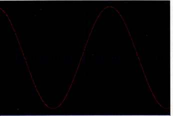
Above: Fig. 2: Output of the oscillator.
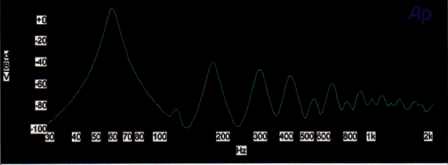
Above: Fig. 3: Noise and distortion response.

Above: Fig. 4: Filter layout.