This innovative design features a National Semiconductor IC ("chipamp") in a vacuum tube topology.
For years I have thought about building an amplifier with output tubes and transformer driven by a solid-state front end and driver stage. But I put the idea aside be cause I wanted to use integrated circuit operational amps to avoid the complexity of designing the driver stage with discrete components, and, to my knowledge, there wasn’t a suitable IC op amp available. About a year and a half ago, that changed when National Semiconductor introduced the LM4702, a high voltage dual opamp intended for use in high-fidelity amps with solid-state output stages. In the commercial grade you can operate it from a ±75V power supply, which is more than adequate for the driver stage of a tube amp.
When the output devices of a class AB power amp are properly biased, there is a small overlap in the signals delivered by these devices. Class AB amps that employ solid-state devices in their output stages generate extremely fast switching transients when one device switches off and the other switches on. Traditionally these transients are nulled out with large amounts of negative feedback.
But this can cause an effect called transient intermodulation distortion. This is because the input stage where the error correction takes place has a difficult time handling the slew rate of these transients. This effect is difficult to measure, but it’s audible. It’s my opinion that this phenomenon is what makes tube amps sound different from solid-state amps.
CIRCUIT DESIGN
Using the LM4702, I designed a hybrid audio amp that uses a solid-state input and phase-splitting driver stage feeding a push-pull vacuum tube output stage typical of conventional vacuum tube audio amps. The input stage is composed of a non-inverting operational amp that accepts the input signal and negative feed back signal. The driver stage uses the LM4702 with one amp inverting and the other non-inverting, thereby providing the phase-splitting function with sufficient voltage swing needed to drive the control grids of vacuum tubes in a push-pull output stage. The combined gain of the input and driver amps is set to emulate their counterparts in a conventional vacuum tube amp. The gain is set higher than the overall closed loop gain of the amp by a factor determined by the amount of negative feedback that you desire.
For the solid-state operational amps I used Burr-Brown’s (Texas Instruments) OPA134 for the input stage and National Instruments’ LM4702 high volt- age dual op amp for the driver stage. You can achieve much lower distortion in the input and driver stages with these amps than you can typically achieve with input and driver stages using vacuum tubes. This combination takes advantage of the strengths of both technologies.
The basic topology of the hybrid amp is shown in Fig. 1. It’s typical of the topology found in many conventional vacuum tube amps, with the exception that the input amp and phase-splitting amps are solid-state. The input is connected to the non-inverting input of opamp U1, and the output of the feedback network of R7 and C3 is connected to the inverting input of U1. Resistors R1 and R2 form a local feedback loop that sets the gain and stabilizes this stage of the amp.
The output of this stage feeds two operational amplifiers U2a and U2b. U2a is configured as an inverting amp with resistors R3 and R4 setting its gain. U2B is configured as a non-inverting amp with resistors R5 and R6 setting its gain. The gains of U2a and U2b are equal in magnitude but opposite in polarity, thereby producing the required phase-splitting function.
The DC voltage of this stage is isolated from the output stage by capacitors C1 and C2. This is necessary because the control grids of the output tubes must be negatively biased with respect to their cathodes. The DC bias network performs this function. The output tubes are connected to the primary winding of the output transformer.
The secondary winding of the transformer is connected to the load and to a feedback network of resistor R7 and capacitor C3. Resistor R7 in conjunction with resistor Ri1 sets the overall closed loop gain of the amp in the audio range. Capacitor C3 is not always necessary, but when it’s employed, it will reduce the gain of the amp above the audio range and in some cases may be necessary to stabilize the amp.

PHOTO 1: Hybrid amplifier with triode transformers.

PHOTO 2: Hybrid amplifier chassis wiring.
THREE EXAMPLES
I’ve built three amps with this topology. The first, a mono amp, uses the trans formers out of an Eico HF-20 integrated amp that I bought at a flea market years ago. The Eico used 6L6GC output tubes, but I was able to upgrade to EL34s be cause I didn’t need to provide filament current to preamp and driver tubes. The result was great. I achieved nearly 40W versus 20 that Eico specified and with less than 0.1% TM distortion. And it sounded great.
The second is a stereo amp that I built around Acrosound TO-330 output transformers, which I had from amps I built using Eico’s HF-60 circuitry I powered the amp with a Toroid of Maryland Transformer, P/N 326.5072, which was large enough to power the two channels. Again, the results were great. I achieved about 70W per channel.
The only problem these amps have is that the output transformers would be nearly impossible to duplicate. There fore, I decided to build a third amp using readily available parts—transformers from Triode Electronics that are clones of transformers used in the Dyna Mark III. This is the amp that I am describing here. The schematic is shown in Fig. 2 with the power supply in Fig. 3.
Combined gain for the input and driver stage is set to 180. The gain of the driver stage is about 32 or 30dB (National Semiconductor specifies a minimum gain of 26dB for stability). The closed loop gain of the complete amp with a 16-ohm load is set by resistors R3 and R4 which turns out to be about 32. This gives roughly 15dB of negative feedback. Raising the value of R5 would increase the negative feedback and lower the distortion, but the amp sounds so good that I decided not to change it.

Above: Fig. 1: Simplified schematic.
CHIPAMP IC CONSIDERATIONS
Since it was designed for amps with a solid-state output, the LM4702 has a source and a sink output to facilitate biasing the output transistors. This is not needed in this application, so I’ve just tied the source and sink together. The LM4702 requires external compensation. C6 and C7 fulfill this requirement.
The LM4702 will dissipate approximately 3W with the power supply used here. Without a heatsink, the temperature rise would be 300 C per watt. You should use a heatsink with a thermal resistance of 70 C per watt or less to keep the rise within reason. I’ve also put ventilation holes in the PC board under the heatsink.
Provision for wiring a mute switch is provided on the PC board. If you’re not going to use one, you should put a jumper on the board in place of the wiring to the switch.
The output stage is pretty typical. It’s wired for ultralinear operation to maximize the power output. I put a 1 fuse between ground and the cathode resistors of the tubes. Tubes do short on occasion and this affords a degree of protection for the high voltage supply and output transformer.
The 10-ohm cathode resistors provide a convenient place to measure the bias and balance of the output stage. I included an AC balance pot R8 in series with resistor R8a. This allows the gains of the two driver amps to be set exactly equal. You could substitute a 51k resistor for R8 and R8a with satisfactory results.
POWER SUPPLY DESIGN
The high voltage and bias supplies are not regulated but are highly filtered. I needed to add a second power supply transformer (Hammond 166 G100) for the solid- state input and driver stages. Power to the LM4702s is regulated using adjustable 3-terminal regulators.
I set the driver stage voltage to ±60V, which is higher than the maximum al lowed for the LM317 and LM337 regulators, but National Semiconductor outlines a clever technique for overcoming the limitation in its linear brief, LB-47. The zener diodes ZD1 and ZD3 keep the voltages across the regulators well within their voltage limits. The ±15V supplies for the input op amp are derived from the ±60V supplies with simple shunt regulators.

Above: Fig. 2: Hybrid power amplifier schematic.
I left space on the PC board for resistors R29 and R36 to dissipate some of the heat that would otherwise be handled by the transistors and regulators. It turned out they weren’t necessary, so I just put jumpers in their place. The output voltage of the positive regulator is determined by the equation:
VCC+ = 1.25 * (1+R32/R33) + 0.00005*R32
Similarly, the voltage from the negative regulator is:
VCC- = -1.25 * (1+R40/R39) - 0.00005
The large filter capacitors preceding these regulators are necessary to keep ripple voltage low enough to ensure adequate headroom for the regulators.
MECHANICAL ASSEMBLY
I used a 1/8” thick aluminum plate for mounting everything. This is thick enough to drill and tap, which facilitates mounting parts under the transformers. I drilled a ring of ventilation holes around each output tube and cut a large hole in the plate where the main printed circuit is mounted. I mounted the lower voltage power transformer under the main power transformer and a terminal block to select the output impedance of the amp under the output transformer. If you do the same, make sure the screws are flush with the top of the plate before mounting the main power and output transformers.
I like using dual banana plugs for connecting the speaker to a pair of 5-way binding posts, and using the terminal block to select the output impedance means that I have only two wires going to the back panel. The large hole has two advantages. First, it allows access to both sides of the PC board, and, second, it al lows for ample ventilation.
The PC board is mounted under the hole with spacers, and a cover plate is mounted with spacers above the hole. Mount a smaller PC board containing the high voltage filter capacitors in front of the power transformer and also mount a number 8 screw next to it to serve as a connection point for a star ground. All grounds are tied to this point.

Above: Fig. 3: Power supply for hybrid amplifier.
You can mount this assembly in either a wood or metal base. A back panel is used for the main power connector, fuse, switch, and input and output connectors. I made the bottom plate out of 1/8W thick aluminum and put holes under the tubes and PC board.
FINAL ASSEMBLY AND ADJUSTMENTS
You should use a socket for the input op amp U1, and you need to solder the LM4702 driver IC directly to the PC board. Fully populate the board with the exception of jumpers J1 and J2 and don’t insert the input op amp. This will allow checking out the power supplies without risking damage to the op amps.
With the amp otherwise fully wired and the output tubes not yet inserted, you can turn on the amp and measure the voltages. Table 1 gives the voltages that you should find. Use extreme care when measuring high voltages, which, in this case, are high enough to be lethal.

Above: Fig. 4: PC board with component layout.

Above: Fig. 5: chassis wiring for hybrid amplifier.
TABLE 1: Preliminary measurements before installing tubes

Note: High voltage DC and raw bias voltage will vary with line voltage. Measurements in these tables were with line voltage at 120V AC and no input signal.

(above) PHOTO 3: Hybrid amplifier with cover off. (above) PHOTO 4: Hybrid amplifier,
bottom view.
Once you’ve checked out the power supplies, remove power and wait about five minutes for the filter capacitors to discharge. Plug in the input op amp, install the jumpers installed, and then you can test the input and driver stages. With a small signal applied to the input—say 0.1V RMS at 1kHz— you can adjust the AC balance pot to get equal AC voltages from the output of the amps in the driver stage. (Note that the mute switch must be closed to get anything out of the LM4702.)
Once this is done, you should remove the signal and short the input. Prior to inserting the output tubes, preset the bias and balance pot. You should set the balance pot at its mid point and the bias pot filly counterclockwise (zero ohms). Pins 5 of all the output tube sockets should read —45V or more negative. If they don’t, then something is wired • wrong and needs to be fixed before proceeding. Output tubes, which are expensive, can easily be damaged if the bias voltage is not negative enough.
With the power supplies checked out and the input and driver stages working properly, and again waiting for the filter capacitors to discharge, you can in stall the output tubes. You need to put a dummy load across the output terminals before turning on the amp. Without it the amp will be unstable and damage to the output transformer can occur.
Now you can adjust the bias and balance pots. You should short the input jack for this procedure. While the tubes are warming up, monitor the voltage across one of the 1011 cathode resistors (test points 1 and 2 or test points 1 and 3). If it exceeds 0.8V, turn the amp off and look for wiring problems.
After the tubes have had time to warm up—say 3 or 4 minutes—adjust the balance pot for equal voltage on the cathodes (zero volts between test points 2 and 3). Next measure the voltage between test points 1 and 2 and slowly turn the bias pot clockwise to get a 0.6V reading. Let the amp set this way for an hour or so and then readjust the balance as before, and then adjust the bias for a reading of 0.75V between test points 1 and 2.
The amp should now be functioning. The output tubes will change slightly during a burn-in period. After a few days or a week of use, recheck and adjust the bias and balance if necessary.
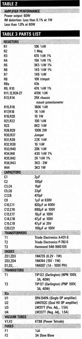
(below) TABLE 2: AMPLIFIER PERFORMANCE
- Power output: 60W
- IM distortion: less than 0.1% at 1W
- Less than 1.0% at 60W
(below) TABLE 3: PARTS LIST: RESISTORS, etc.