|
|
You can configure this versatile power supply for use in tubed and a variety of other projects.
This project began with an amplifier. I was working up a small, tubed, “Champ”-class guitar amplifier, and the first step was inevitably to build its power supply, so I could begin experimenting with the audio circuits. Like all guitar amps in my experience, it would have several stages of filtering to power the various sections of the amplifier. It would not, however, use active regulation.

As I was working out the design, I realized that this type of power supply is applicable to a variety of projects. Many people are building tube doohickeys of one sort or another—microphone preamps, compressors, guitar amps, clones of classic tubed gear—and each one needs a power supply. Why reinvent the wheel every time, and design a board for it to boot?
I began designing the board using a new open-source layout program, Free PCB (www.freepcb.com); along the way I decided to make the board layout as flexible as possible, so it could be used for a broad range of projects. I wound up with a design and board that can be used for any application requiring a well-filtered power supply with a nominal voltage level up to 350V. Along the way, I found ways to make it sit up and do tricks, up to and including regulation.
WANT LIST
As always, step one in the design was figuring out what I wanted it to do. First, I wanted the supply to be usable with either tubed rectifiers or solid-state. With solid-state diodes, I wanted the option of using RC snubbers as described by Jim Hagerman as well as the anti-resonant series resistance suggested by Ben Duncan I wanted the diodes, if solid-state, to be usable either as a center-tapped full-wave rectifier or a full-wave bridge. I wanted users to have the option of LC filtering, and, for safety reasons, I wanted a bleed resistor to bring the voltage down quickly when the power gets turned off.
I also wanted to offer jumper-selected options for the filter circuits: a standard ladder, in which each stage’s filter taps off the previous one, or a variant which allows two filters to fan out independently. Finally, I wanted users to have the option, in each stage after the first, of using a standard star ground or a different grounding scheme (again jumper-selected).
There was some pleasant serendipity. By using two series resistors for the bleeder, I could elevate a filament supply above ground, either for hum reduction (an AC filament is less likely to radiate into the adjoining cathode when it’s biased above the cathode’s DC level) or to avoid exceeding heater-to-cathode limits when a tube is being used as a cathode follower, SRPP, or similar circuit.
I found I could use the spaces for the two series bleed resistors for zener di odes instead, producing a simple regulator; by adding an external pass transistor (and heatsink) I could even implement a full emitter- or source-follower regulator.
I called my design the Gamp supply, named for the little guitar amp that was its first purpose. It’s a general-purpose supply, but it’s important to observe that 350V limit on the nominal voltage. When designing supplies, I assume that AC line voltage will vary ±10%. If the nominal voltage is 350V, then the voltage when the line is 10% over normal will be 385V. There are standard safety guidelines for the maximum voltage permitted between traces on a PC board for a given spacing; a handy online calculator is at:
www.desmith.com
When designing this board, I used a minimum gap of 0.1” (100 mils) in most locations, which corresponds to just over 385V. If you try to run the boards hotter, you risk having the voltage arc over between traces, damaging the board and blowing either a fuse or your transformer. (There are a couple of conductors on the board that have closer spacing, but they are all ground traces and should have no voltage differential between them.) For those needing a higher voltage supply (to feed, say, a Dynaco-class power amp or a bigger guitar amp), that’s on my to-do list.
BASIC DESIGN
The power supply design is shown in Fig. 1. Note that most of the part designations are not filled in; parts selection is open-ended as long as you use components that fit the spacing of the board, which is set up for bog-standard sizes. The electrolytic capacitors C4, C8, and C10 can be as large as 270uF 1” diameter, Panasonic TSHB series or equivalent). I left room for C6 to be larger (1.4") it can be up to 470uF/ 450V if you like. The whole TS series of caps has the same pin spacing, so you can also use smaller ones: 33 for example, in the TSHA series.
The bypass capacitors (CS, C7, C9, and C11) are presumed to be polypropylenes, again in standard sizes; I included mounting holes for 0.1uf caps from Panasonic’s ECQ-P series at either 400V or 630V.
For input and dropping resistors R8- 11, I made room on the board for 5W sand-cast power resistors; it’s also possible, of course, to use lower-wattage resistors if the design warrants. The bleeder string (R12-13) is designed to pull 1mA of current; note that R13 is specified as 75k, which will provide 75V at the junction of R12-R13 for filament elevation.
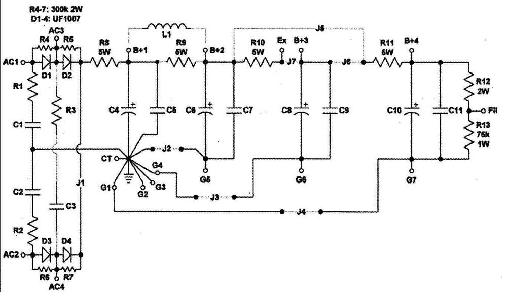
FIGURE 1: Gamp power supply.
INPUT SECTION
I’ll talk first about hooking up the board with solid-state rectifiers. The most common connection for tube circuits is a full-wave center-tapped design (Fig. 2a). The transformer’s plate leads (red) are connected to the AC1 and AC2 terminals on the board, while the transformer plate winding’s center-tap (red-yellow) is connected, logically enough, to the terminal marked CT.
The diodes specified have ultra-fast turnoff times to minimize generation of radio-frequency crud that can leak into audio circuits. To ensure that they never see a reverse voltage higher than they can stand, each leg has two diodes in series, with parallel resistors (R4-R7) that ensure voltages across the diodes are equal. (Old trick from the Radio Amateur’s Handbook.)
For further protection against RF interference, I’ve included room on the board for Hagerman-style RC snubbers. At Jim’s suggestion, I treat each half of the transformer secondary as a separate winding, so there are two snubbers, R1-C1 and R2-C2. (For information on how to calculate resistor and capacitor values in the snubbers, please see his article.) R8 is the input damping resistor a la Ben Duncan. In this full-wave center-tapped configuration, R3 and C3 aren’t used.
What if you have a transformer with out a center tap? In that case, you’d use a full-wave’ bridge rectifier (Fig. 2b). The transformer’s plate leads now go to terminals AC3 and AC4, and the single snubber consists of R3-C3. R4-R7 are omitted, along with R1-R2 and C1-C2. Terminals AC1 and AC2 are connected to each other, and to terminal CT. I’d originally envisioned a heavy wire from AC1 to AC2, and another wire connecting the centerpoint of that wire to CT, but I realized you can make the connection by inserting jumpers in place of R1, R2, C1, and C2. (Nice, heavy wires, if you please.)
Tubed rectifiers are almost always used in full-wave center-tapped circuits; Fig. 3a shows the hookup for an indirectly heated tube (e.g., 6X4), while Fig. 3b shows the hookup for a directly heated tube (e.g., 5AR4). The tube’s cathode connects right to terminal B+1; all of the components associated with the solid- state diodes, including R8, are omitted. Note that tubed rectifiers have limits on the size of the first filter capacitor; these restrictions aren’t completely graven in stone (I’ll discuss them when I do a worked example later), but you should keep them in mind when designing a tube-rectified supply.
FILTERING: VARIATIONS ON AN RC THEME
First, the filter doesn’t need to be RC.
It’s easy to substitute off-board chokes for any of the dropping resistors in the filter sections—I’ve shown one in Fig. 1 between B+1 and B+2, but you could use chokes on B+3 and B+4 if you desire. In fact, you could leave out C4 and C5 entirely, and make the Gamp a choke-input supply. Nobody would complain.
I mentioned that the board has room for a really big capacitor at C6, to run an output stage perhaps, or to stabilize a screen voltage. Why there, in the B+2 stage, rather than the input?
As noted in the previous section, tubed rectifiers don’t like to see large capacitors in the first filtering stage; it can shorten their lifetimes. Solid-state diodes are more forgiving, but they still undergo a lot of stress from inrush current at the moment of turn-on. The first filter capacitor acts like a dead short until it’s charged, and because a bigger cap takes longer to charge, the stress on the diodes is prolonged. C6, on the other hand, is on the downstream side of R9 (or L1), which acts as a current limiter, minimizing stress on the diodes. (The turn-on stress is instead on R9, so it’s worth using a 5W unit here even if its normal operating dissipation will be much lower.)
Next down the line are two mysterious-looking jumpers, J5 and J6. What are they about?
Look at Fig. 4a. That’s the usual design of an RC-filtered power supply; each stage feeds the next. On this board, you’d choose that option by including J6 and omitting J5. But what if you’d prefer something like Fig. 4b? Perhaps you need two separately decoupled filters with the same DC voltage; you’d select that option by connecting J5 and omit ting J6.

FIGURE 2A: Full-wave rectifier, center-tapped transformer.

FIGURE 2B: Full-wave bridge rectifier.
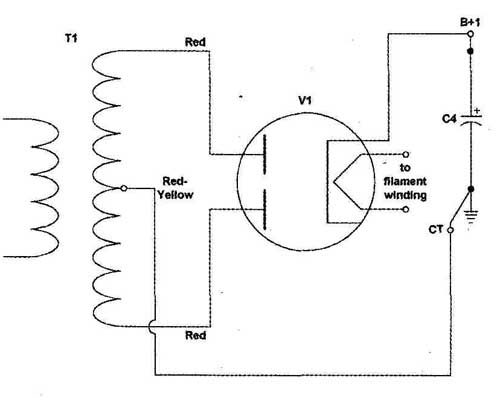
FIGURE 3A: Tubed rectifier, indirectly heated.

FIGURE 3B: Tubed rectifier, directly heated.
I designed the bleeder string, R12-R13, to draw 1mA from the supply at full voltage. R13 is specified at 75k; it dissipates 75mW, so its 1W rating provides a good safety margin. The value of R12 depends on how many volts it drops; I’ll look at that when I work out an example.

FIGURE 4A: Cascaded filter, bypass caps omitted for clarity.

FIGURE 4B: Fanout type filter, bypass caps omitted for clarity.
SEEING STARS
Most audio projects use a standard “star” ground; every power supply section, and every audio section, is grounded directly to the main grounding point, often (as here) the negative terminal of the first filter capacitor. The chassis is also connected to this point (this board has a terminal for that, pin ChG). To implement a classic star ground on the Gamp supply, use J2-4 and connect the audio stage grounds to the terminals G1-4.
Not everyone prefers to use this grounding scheme, though. It’s some times quieter to use a different, non-star hookup (Fig. 5). In this arrangement, the ground on the filter capacitors connects directly to the audio stage’s ground point, which then sends a ground wire back to the main grounding point. It’s easy to do this on the Gamp simply by omitting that stage’s grounding jumper (J2, J3, or J4) and connecting the capacitor ground terminal (G5, G6, or G7) to the audio circuit’s grounding point, wiring the latter to G2, G3, or G4. You can, of course, mix and match the ground arrangement on the various stages; I’ve found it useful on a guitar amp, for example, to use a star ground on B+2 and B+3, but the alternate hookup on B+4 (which feeds the audio input stage).
GETTING FANCY
It’s easy to connect the bleeder string to elevate a filament supply above ground. With an AC filament supply, simply hook the terminal marked Fil to the center tap of the transformer winding or, if it’s not center-tapped, to the junction of a pair of matched 10k resistors hooked across the winding. (There isn’t room for these on the board; use a small terminal strip.) A DC filament supply is equally easy; hook the 0V terminal of the supply to the. Fil terminal instead of ground.
Hoisting above ground cuts hum radiation from an AC filament supply, but it also can keep tubes operating properly. Every tube has a maximum heater-cathode rating, and for long life and good performance it’s a bad idea to exceed that rating. A cathode-follower circuit, or any of the totem-pole circuits popular in recent years, has a cathode that sits well above ground, sometimes as high as 150V. That’s above the heater-cathode rating of most tubes, and I’ve seen 12AU7s start to arc under those conditions.
A 75V bias, used with a 150V cathode follower, brings the heater cathode voltage down to 75V, well below the 90V rating common to many tubes. It’s low enough, however, that it won’t cause problems for a voltage amplifier in the same circuit, which might have a cathode sitting at 4V.
It’s possible to include a simple regulator. The holes for R12-13 are sized so you could place a pair of 5W zener diodes there; R11 now becomes the current-limiting resistor for the zener string. You can use this variation whether the B+4 section is wired for ladder or fan-out (J6 orJ5). Depending on the zeners’ voltage, you could still use the Psi terminal to elevate a filament supply.

FIGURE 5: Alternative ground hookup.

FIGURE 6: Full emitter-follower regulation. J5 is used, J6 and J7 are omitted;
ZD1 and ZD2 are substituted for R12 and R13. R11 serves as current-limiting
resistor for the zener string; R10 as dropping and current-limiting resistor
for the pass device. You should mount the pass device Q1 on a heatsink which
is mounted off-board. R14 is a stopper, which you should connect directly to
the pass device. Q1 could also be a MOSFET or Darlington pair.
FULL REGULATION
Once I designed the zener-regulated variant on the Gamp, I realized that only one more jumper was needed to implement a fully-regulated emitter- or source-follower supply. Look at Fig. 6; in this circuit J7 is omitted, R10 acts as a current-limiter and/or dropping resistor for the pass device, and R11 plus the two zeners supply the base or gate with a reference DC voltage. The capacitors at B+3 and B+4 now act as bypass caps for the regulated output and the reference voltage, respectively.
It’s important to calculate dissipation on the pass device carefully (including what happens when the line voltage is 10% high) and use adequate heatsinking. The stopper resistor (Ri4) is also important, because it keeps the pass device from breaking into oscillation; you should connect the stopper (with short leads) directly to the base or gate terminal of the pass device.
If the pass device is bipolar rather than a MOSFET, the regulator will have a lower output impedance if you use a Darlington configuration.
MECHANICAL CONSIDERATIONS
The four mounting holes in the board are sized for 4-40 screws. Because of the high voltages on the board when it’s used for tubed circuits, I strongly recommend you mount the board on non-conductive standoffs.
All of the square input-output connecting pads on the board are drilled for 0.042” pins; while it’s certainly possible to solder wires directly into the holes, I don’t recommend doing so for most home construction projects. Changes in hookup, desoldering, and resoldering are almost inevitable accompaniments to experimental designs, and these take their toll on printed circuit boards, leading to lifted traces and unreliable connections.
Making changes to pins is much less destructive; for several years now I’ve used Vectorbord K3OC/M pins, which are easy to insert (even without a specialized tool) and hold up well. They project below the board; be sure to take that into account when choosing the length of your standoffs. Ideally, the bottom of the pins should be at least ½” from the mounting surface. You can get 1000 of them for about $50 from Mouser Electronics, which ought to last a very long time. Be sure the cat doesn’t knock over the can.
(Note: I discovered after writing the first draft of this article that the K30C/M pins seem to have been discontinued. Nuts! But there are still plenty of other 0.042” pins available.)
Nicely flush components look neater on the board, but run hotter. I mount rectifier diodes, resistors, and zeners about 14” above the board to let some air circulate around them; this also keeps any heat they generate from toasting the board quite as badly. You can use plastic spacers on the leads, but I think those are necessary only when the leads are light gauge and liable to flex.
Note that while J2-7 are used to select options on the board, J1 is mandatory. That was the only trace I could not route on the bottom side of the board, and it seemed wasteful to turn this into a two-sided board for a single trace. Use 18-gauge wire, insulated, for this and the other jumpers; at the low currents normal for low-powered tubed circuits, heavier wire won’t make a difference.
OTHER USES
Just because this supply board was de signed for tubes’ B+ circuits, that doesn’t mean it can’t be employed elsewhere. You could, for example, use 75V capacitors with an appropriately sized transformer to produce a +48V phantom power sup ply, regulated or otherwise.
Let me remind you again that this board is designed only for nominal voltages (at B+1) of 350V or below, with a +10% permissible overvoltage. Anything higher, and you’re out of bounds. 350V, of course, is plenty high to zap you good and proper; exercise appropriate caution as you would around any dangerous voltage. Unplug the supply and Wait for the bleeder resistors to do their work be fore you get near the board, or any other energized parts in your project.
PARTS AND CHOICES
Table 1 is a generic parts list. The parts that never vary are shown in detail, while the others are given more generalized descriptions. The resistor values (except for R13) are left open; fill in the xxx designations in the part numbers. Most of the parts are available in the US from Digi-Key, but I’ve included the option of using 10nF 1kV ceramic disc capacitors in the snubbers. Digi-Key inexplicably doesn’t carry these, but Allied Electronics does. They have a minimum purchase, though, so you’ll want to order other items at the same time.
The capacitors listed are the maximum values that will fit onto the board; as you’ll see in the worked example, you may choose not to use the biggest caps. Snubber parts on the generic list are left wide open; see Jim Hagerman’s article for information on choosing them.
You’re not, of course, limited to the brands I specified. Snap-in capacitors come in standard case sizes, and you could easily substitute Nichicons or an- other brand if you prefer them. The resistors’ sizes are pretty standard, too. If you go with solid-state rectifiers, though, do stick with the ones I specified, or seek out similar fast-switching diodes.

TABLE 1 Basic Parts List
A WORKED EXAMPLE
Look at a typical application for this board. I chose a small guitar amp—in fact, the one that inspired the board’s design. It uses an ELS4 power pentode, single-ended, and two halves of a 12AX7 as an input amplifier and a driver. The power requirements are:
Screen----262V at 4.25mA
Driver-----200V at 0.45mA
Input----172V at 0.45mA
For straight cascaded filtering 1>2>3>4, I’ll use J6, and omit J5. The transformer’s center-tapped, and I want to use a 6X4 rectifier tube, so I’ll leave out all the rectifier diodes on the board, along with their snubbers and parallel resistors, and RS; the cathode of the rectifier tube will connect directly to B+1.
I’ll use star grounding for the screen and driver sections, but a “looped” ground (I don’t have a better name for it) for the input section. That means I’ll include J2 and J3 but omit J4; I’ll run a wire instead from G7 to the input stage ground, and another from that ground to G1.
How much current will I draw from each supply terminal? Remember that the filter sections are cascaded, so each one not only supplies its audio stage, but also provides current for the next section. The last stage also supplies 1mA of bleeder current. The supply requirements now look like this:
B+1 = 280V; i = 44.55mA
B+2 = 262V; i = 6.l5mA
B+3 = 200V; i = 1.9mA
B+4 = 172V; i = 1.45mA
Fil float = 75V; i = 1.0mA
Ohm’s law determines the resistor values:
R9 = (B+1 - B+2)/i = 18V/6.l5mA = 2,927 R10 = (B+2 – B+3)/i = 62V/1.9mA = 32,6321) Rh = (B+3 - B+4)/i =
28V/1.4SmA • 19,3100
R12 = (B+4 - ff1 float)/i = 97V/1.0mA = 97k
How much power will they dissipate? Under steady-state conditions, using the nearest standard values and computing power dissipation using the formula d = i * R:
R9 = 3k; d = 0.113W
R10 = 33k; Pd = 0.119W
R = 20k; 1 = 0.042W
R12 = 100k; Pd = 0.1W
That’s pretty benign; you’d think the resistors could all be half-watt units. There’s a pitfall, though: During turn-on, as C4 is charging, C6’s voltage will lag behind it, so a significant voltage difference will appear across R9, and that will dissipate wattage. Resistors can stand a surge greater than their rated power for a short time, but not beyond, and for best reliability it’s wise not to push them.
If this supply used solid-state rectifiers, I’d make all the resistors nice and hefty, just for insurance. With a slow-turn-on tubed rectifier, it’s less of an issue, so I think 2W carbon comp or metal oxide resistors will be adequate for R10-12— besides which, 5W wire-wounds are hard to find in values greater than 3k. Oops: In fact, Yageo doesn’t make them bigger than 2k. So I’ll need to find another brand for R9. Huntington will do (next page in the Digi-Key catalog).
OK, how about capacitors? The makers of tubed rectifiers tell you not to hang huge capacitors on them, because it shortens their lives drastically. Well, I can test that a 68uF cap in the C4 position doesn’t seem to have shortened the rectifier’s life in the little Kalamazoo guitar amp that inspired this project; the 6X4 that was there when I bought the amp four years ago is still chugging along happily. That’s not a scientific experiment, perhaps, but it’s a good enough data point for the moment. I’ll use a 68uF 450V cap for C4.
What will the ripple be? First, it’s necessary to figure out what the equivalent load on the supply is, in ohms. B+1 = 280V, and it’s supplying a total of 44.55mA; by Ohm’s Law, the equivalent load is 280/0.04455, or 628 ohm).
There’s a calculator at hyperphysics (web site) that computes approximate ripple voltages. Plug in a VPk of 290V (an approximation, but it’ll do) and an equivalent load of 628 ohm), and you get approximate ripple of 1.4V. Does that seem high? The original amp design used a 20uF capacitor on B+1, and that should produce a ripple voltage of about 5.5V. The amp didn’t produce any audible hum; part of the reason was power-supply rejection in the output circuit, but the more significant reason was that the speaker, in its open-backed cabinet, has significantly puny response at 120Hz. Sometimes b-fl lets you get away with murder.
What about subsequent stages? Say I made the caps 47uF apiece. The resistor-capacitor combinations form low- pass filters; the low-pass filter for B+2, for example, is formed by C6 and the parallel combination of R9 and R10. Its cutoff frequency is 1.23Hz. The ripple frequency is 120Hz. (I live in the US; in most of the world, the ripple frequency would be 100Hz.)
Because a passive RC filter approaches 6dB/octave attenuation, the ripple will be reduced at B+2 by a factor of about 1.23/120, or 0.0103x. If the ripple at B+1 is 1.4V, the ripple at B+2 will be about 14mV.
I’ll spare you further arithmetic; here are the ripple voltages at the four terminals:
B+1: 1.4V
B+2: 14mV
B+3: 32mV
B+4: 51nV
Just for reference, that last number is about -144dBu. Cascaded RC filters are powerful tools.
Wait a minute, though. This is a guitar amp, not a hi-fi amp. What if I wanted a nice, saggy, badly regulated supply, like the gloriously dirty amps of old?
It’s doable; Panasonic’s NHG and EB series caps come in smaller capacitance values at appropriate voltages, and I could duplicate the little Kalamazoo’s original 20-10-10uF supply cascade if I wanted to. These caps have radial leads 7.5mm apart instead of the 10mm pin spacing standard on TS-series caps and their equivalents, so I’d need to spread the leads a bit. For mechanical stability (guitar amps get slammed around), it’d probably be a good idea to hot-glue such caps in place.
For bypass caps, I’ll use the smaller 0.1uF 400V Panasonic polypropylenes.

TABLE 2 Parts List, Worked Example
PHOTO 1: The Gamp power supply board.
Table 2 is a detailed parts list for the worked example. Note that several of the pieces aren’t used, because I’m using the board with a tubed rectifier. The cost column is drawn from my most recent printed Digi-Key catalog; prices have been fairly stable lately (knock wood!), but to get more exact figures you should check their website.
The total cost for the supply board, including the rectifier tube and its socket, is about $28, which doesn’t include the power transformer, nor mechanical parts (standoffs, screws, terminal pins, and the board itself). Photo 1 shows the board stuffed and wired for the above example. For now, I decided not to bypass filter capacitors after the first stage.
ENVOI
What began as a simple design for a particular project evolved into something more flexible. It’s still simple in concept, but the details have been left as loose as possible; you can configure the board in many different ways, and I’m sure there are folks who will make it sit up and do tricks I haven’t thought of.
Good power supplies are the back bone of good audio. This board will, I hope, provide the backbone for many good projects. Enjoy!
SHOULD YOU MAKE ONE?
For many years I made my own circuit boards, but I’ve sworn off. The chemicals involved are toxic, and what do you do when they’re no longer useful?
A professor of mine once postulated a series of laws having to do with environmental issues, and one of them was, “Everything has to go somewhere.” The chemicals industrial circuit board makers use are just as toxic, but they have disposal resources not available to home users, with government inspectors looking over their shoulders to make sure the chemicals are disposed of as safely as possible. I hope.
If you still want to make your own boards, the foil side is shown in Fig. 7, and the component side in Fig. 8.
I’ve done a run of the boards, with silk screening and solder masking, produced and drilled by Futurelec. They did a good job. I’m selling the boards for $24 apiece plus shipping and handling

FIGURE 7: Foil side.

FIGURE 8: Component side
REFERENCES
1. Jim Hagerman, “Calculating Optimum Snubbers,” 1/98 Audio Electronics, p. 26.
2. Ben Duncan, “A State-of-the-Art Preamp: AMP 02,” Hi-Fi News & Record Review 34:11 (November 1989), p. 45.
SOURCES
Allied Electronics, Inc.
7410 Pebble Drive
Fort Worth, TX 76118
1-866-433-5722
www.alliedelec.com
Digi-Key Corp.
701 Brooks Ave. South
Thief River Falls, MN 56701
800-344-4539
www.digikey.com
Triode Electronics
5633 W. Irving Park Rd.
Chicago, IL 60634
733-871-7459
http://store.triodestore.com
[the discussion above is adapted from an article outlined in audioXpress .com">audioXpress Jul. 2007]