The purpose of wiring is to translate a theoretical circuit diagram into a practical, working circuit. Unfortunately, there are many pitfalls, and careless implementation can ruin a good design. Fortunately, most of the pitfalls can be predicted easily, and therefore, avoided.
Tools
The cheapest tools are the most expensive ones. Cheap tools make it difficult to do a good job, so they waste time, and they need periodic replacement. Conversely, good tools mean that the quality of the job is limited purely by your own skill, they're nicer to use, and they last a lifetime.
Soldering irons
Obviously you need a soldering iron, but what is the difference between them and why are some so cheap? The job of the iron is to heat the parts to be soldered to a temperature such that once the solder is applied, it melts quickly and flows to form a perfect joint. Almost anything will do this, but the component may not work afterwards. Two thermal properties characterize the iron; thermal mass and temperature. Thermal mass is simply the mass of the hot part of the iron, and the greater this is, the more difficult it is for the proposed joint to cool it.
A cheap iron determines its temperature by only generating sufficient heat to match its losses to the environment, and to keep the tip hot enough to melt solder. As soon as it is touched to the joint, it begins to cool. If the work is not to cool the iron down so much that it is unable to melt solder, then the iron must contact the joint at a rather higher temperature. A higher thermal mass helps, but makes the tip clumsy to use. The upshot of all this is that the iron usually runs too hot, burns the flux in the solder, and may well damage the components. It will almost certainly cause tracks on printed circuit boards to lift if used for desoldering.
A better iron is thermostatically temperature controlled, and has an over-sized element (typically 50W as opposed to 12-25W).
The iron is at the correct temperature all the time, but when the joint cools the tip, the thermostat trips and the over-sized element quickly restores the correct temperature. Additionally, temperature-controlled irons are generally low voltage (usually 24V), which makes them longer lasting (the wire of the heating element is thicker, and less liable to break). Because the tip doesn't overheat, it is less likely to damage fragile components like polystyrene capacitors, and it lasts longer whilst being easier to keep clean.
All soldering irons suffer from leakage current between the heating element and the tip. The electrical insulation between the element and the tip must be thin in order to transfer heat quickly and efficiently, but because it is thin and hot, this insulator cannot be perfect (insulators become more leaky as temperature rises). Ohm's Law dictates that the leakage current is determined by the electrical resistance of the insulation and the voltage applied to the element, so low-voltage irons have far lower leakage than mains irons. This point is significant because semiconductors such as CMOS digital ICs and low noise discrete transistors or ICs can be damaged by the leakage current from a mains iron.
Because low-voltage temperature-controlled irons need a mains transformer and are more complex, they are invariably more expensive than cheap mains irons. However, they pay for themselves in time, because elements and bits last far longer, and they are less likely to damage a printed circuit board or an IC. And, in all that time, they are far nicer to use.
Remember, it is the board (whether PCB or tag strip) that is expensive, not the components. Individual components can always be replaced, but if the board is wrecked, everything has to be replaced.
Ground bus-bars have a large cross-sectional area to reduce electrical resistance, but this inevitably makes them difficult to solder because they conduct heat away so efficiently that it takes considerable time for the iron to raise a part of the bar to soldering temperature, by which time the nearby poly styrene capacitor or IC has already been destroyed. The solution is to use a larger iron which can heat the bar faster -- the author uses a 200W temperature-controlled mains iron (see FIG. 1).
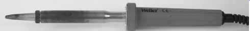
FIG. 1 A 200W iron makes short work of heavy soldering
Tips
The part of the iron that contacts the work is the tip, or in more old-fashioned parlance, the bit. Old-fashioned irons had solid copper bits whose working surface would gradually be dissolved by the solder to become concave and would then need to be filed flat. Filing the bit was also the accepted way of cleaning these irons.
Modern irons use iron-coated tips to protect the copper, and should never be filed. The normal method of keeping the tip clean is to wipe it on a moistened sponge (specially made for the purpose by most soldering iron manufacturers). It is most import ant to keep the sponge moist, and most engineers keep an old washing-up liquid bottle of water near their iron for this purpose.
If the tip becomes sufficiently contaminated by old, dusty solder that a quick wipe on the moistened sponge cannot clean it, then a wipe on one of the proprietary tip cleaners should do the job. If that fails, then careful scraping with a knife or wire wool will cure the problem. Do not be tempted to use silicon carbide or glass paper as the heat melts the glue and makes the tip even dirtier.
Tips come in many different shapes, sizes, and temperatures.
The best tip is conical, with an oblique cut across the end to produce an elliptical soldering surface. These tips are usually specified by the width across the minor axis of the ellipse, and a good general purpose width is 2.4mm. A wider tip allows you to get more heat into the work, and is better for heavier jobs but clumsy, whereas a fine 1.2mm tip is excellent for pick-up arm wires or surface mount ICs but is unable to heat larger jobs.
Ideally, you need a range of tips, and should be prepared to change tip with each soldered joint if necessary (see FIG. 2).
Irons that use a magnetic thermostat, such as the traditional Weller ''Magnastat'' have tips that are available in different temperatures. The tips rely on the Curie effect whereby a magnet temporarily loses its magnetism at its Curie temperature, and this releases a spring-loaded ferrous shaft coupled to a micro-switch in the handle. For most work, a No. 6 (315 degr. C) tip is ideal, but when working inside old amplifiers, a No. 7 (370 degr. C) is better at burning away the dirt that insulates the old solder. Very occasionally, these irons overheat, and the cause is a dud tip. In the unlikely event of this happening to you, try changing the tip before diving in and replacing the switch (much harder).
The most recent irons have their temperature electronically con trolled by a thermocouple, allowing adjustment during use - but this facility is a luxury for amateur work and although these irons are rapidly becoming cheaper, they are not really worth extra expense. A far more important question when you spot a ''bargain'' iron is the future availability of tips - if this is at all questionable, buy lots of tips at the time.
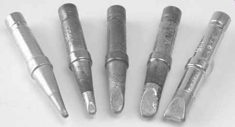
FIG. 2 Selection of useful tips
Gas irons
Portable gas irons burn butane gas without a flame in a tip containing a catalytic convertor (see FIG. 3).
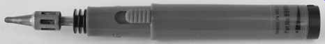
FIG. 3 Although crude, portable gas irons can be useful
Temperature is crudely set by adjusting the gas flow. Because of their haphazard temperature control, gas irons have no place in quality work, yet there are times when they are invaluable.
Very occasionally, a single joint needs to be made (or broken) but a mains socket isn't nearby, so rather than finding an extension lead and the mains iron, a gas iron can be quite handy. The other use is when wires need to be soldered to a replacement heating element for the mains iron.
Solder
The traditional electronic solder was 60/40 self fluxing solder.
The 60/40 referred to the ratio of tin to lead, and the flux is a chemical, that when heated by the iron, cleans the surfaces to be soldered and allows a good joint. Industrially, the use of lead is being heavily discouraged, so pure tin solder is now available, but this requires a rather higher soldering tempera ture, making component damage more likely.
Other solders are available, some of which have sufficiently powerful fluxes to cut through surface aluminum oxide and enable soldering to aluminum. Never attempt to use aluminum solder for electronic work, and once a soldering iron tip has been contaminated by aluminum solder, it should never be used for electronic work.
It is most important to keep your solder clean; keep it in an airtight jar when you're not using it. Drawing it through a clean cloth moistened with isopropyl alcohol before use removes surface contamination, and will significantly improve the quality of your soldered joints. Alternatively, a light rub using metal polish intended for brass easily strips surface contamination, but needs careful buffing to remove all traces of the polish.
In small quantities, solder is expensive, so buy a 500 g reel of solder. In this quantity, there are various different sorts of solder in various thicknesses. An excellent general purpose solder is 0.7mm low melting point solder with 2% silver content. For surface mount components you must use silver loaded solder; otherwise the silver in the plating of the components leaches out and they won't solder. Silver loaded solder will allow you to make far better soldered joints than ordinary 60/40, and you will be seduced by its superior properties.
Soldering and shrink back
Assuming that you have an iron at the correct temperature, with a correctly sized clean tip, and some clean solder of the appropriate type, how do you ensure that you make a perfect soldered joint? The surfaces to be soldered must be clean, and the soldering iron tip must be clean and free of dross. Soldering works by the solder combining intimately with the surface metal of the components, and dirt hinders this process. The solder should be applied to the point of contact between the work and the iron such that it melts and flows immediately; the tip of the iron should then be wiped clean on the moistened sponge (see FIG. 4).
Clean surfaces will wet perfectly, and surface tension causes the solder to flow instantly across the work to form a perfect joint.
Dirt causes the solder to form globules on the surface that do not wet the joint, and defective joints are therefore known as dry joints. There are many variations between these extremes, but it can generally be said that good joints are made quickly, whereas dry joints are more likely to occur when the iron has been in contact with the joint for more than a second or two.
Don't dab at the solder. Press the iron firmly into the work so that the heat flows quickly, apply the solder firmly, let it flow, and release the iron immediately.
The best joints are mechanical joints. If the parts to be soldered are already unable to move relative to one another, then they will not move as the solder solidifies, and a perfect, shiny, joint should result. If there is any movement whilst the solder is cooling, a dull, dry joint will result.
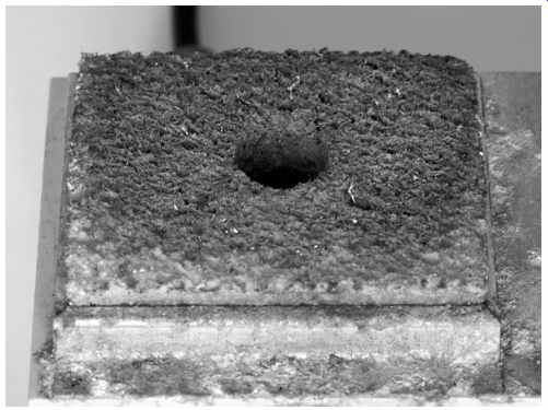
FIG. 4 The tip should be wiped on a moistened sponge before and after
every joint
The best joint is the first joint. Any subsequent resoldering of a joint degrades the joint because it allows further oxidization of the heated materials. If you are forced to resolder an old joint, remove the old solder and replace with new. The fresh flux will ensure clean surfaces, and the fresh solder will be not be contaminated with dross.
When you solder insulated wires, you are likely to encounter a phenomenon known as shrink-back. When you strip the wire, you make a circumferential cut into the insulation, but to avoid nicking the conductor, the cut is not made sufficiently deep to cut all of the insulation. The remaining insulation is broken when the unwanted insulation is pulled away. Inevitably, this has the effect of stretching the remaining insulation along the wire. When the conductor is heated for tinning, the stresses in the plastic insulation relieve, and the insulation apparently shrinks back, leaving more exposed conductor. There are various ways of reducing shrink-back:
-- Use wire that doesn't suffer from shrink-back. Silver threaded down PTFE tubing doesn't suffer from shrink-back because the coefficient of friction of PTFE on silver is so low that the moment the insulation is broken, it springs back to its original length. Again, use a sharp scalpel to make the cut, but instead of rolling the scalpel around, simply press it firmly into the PTFE, and twist the insulation to make the cut.
-- Minimize the stress that causes shrink-back. Make the cut in the insulation using a sharp scalpel. To avoid nicking the conductor, the blade has to be rotated around the wire without any cutting motion. The wire can then be bent very slightly at the cut to break any remaining insulation, rotated slightly, and bent slightly until the insulation is completely broken. The act of bending to break the insulation stretches one side of the insulation but compresses the other, minimizing the total stretching, and therefore the amount of shrink-back.
-- The degree of shrink-back is proportional to the time the iron is in contact with the work and its temperature. This is why it is so important to make fast joints using the correct size tip. A tightly wrapped mechanical joint allows surface tension to make the solder flow quickly.
-- Accept that there will be shrink-back, and pre-tin the conductor, so that shrink-back occurs, then solder the wire in place. Unfortunately, this method precludes mechanical joints using stranded wire, but is satisfactory with solid core wire.
Solder tags
Solder tags are used to make electrical connections to items that have too much thermal mass to be soldered directly. A soldered ground bond directly to a chassis would not only cool any reasonable soldering iron, but the chassis is probably made of aluminum, necessitating special solder, so this is a legitimate use of a solder tag.
Be warned that as parts age, they corrode and become more difficult to solder, and printed circuit board manufacturers refer to this as solderability. Solder tags inevitably lie in drawers for decades before being used, so you may occasionally find a solder tag that flatly refuses to solder. A great deal of time can be wasted abrading the surface in a futile attempt to persuade the tag to solder. If you are unlucky enough to find a tag that won't immediately solder, discard it and pick another, ideally from a different batch.
A solder tag inevitably adds a mechanical contact in series with the soldered joint, so it is always the second-best choice, and should be avoided if at all possible. As an example, traditional amplifier output terminals often came with solder tags, but could, and should, be soldered directly. Part of the thread needs to be removed to form an exposed brass pillar suitable for soldering, this is most easily done with a file, and although a prettier job can be done in a lathe, the setting-up takes time. The wire should be tightly wrapped one complete turn round the exposed pillar and the iron applied to the pillar. Once the pillar is hot enough to easily melt solder, the joint can be finished by sliding the iron so that it touches the wire directly, and a perfect joint will be formed. The thermal mass of these terminals can be greatly reduced by unscrewing the part that grips the loudspeaker cable so that it wobbles freely on its thread, and thus does not have to be heated by the iron. The small 4mm combination terminals can be soldered by a conventional 50Wusing a large tip, but the large 32A terminals are best soldered with a 200W iron.
Desoldering
Sometimes you will need to desolder a joint. If the joint is mechanical, it is best to cut the wires away, otherwise the prolonged heat whilst bending wires will damage the wire or component. The remaining joint has fragments of wire in solder and these must be removed.
The solder can be removed by one of two methods:
-- Desolder wick uses surface tension to wick the solder into copper braid which is discarded once contaminated by solder. Solder wick must be kept clean if it is to work, so store it in an airtight container. This method causes the least damage to the work, but is wasteful and expensive.
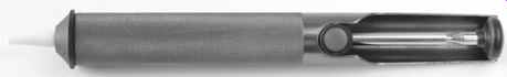
FIG. 5 Handheld solder sucker
-- Alternatively, solder can be drawn off with a vacuum. In industry, vacuum-desoldering stations are common, but they are extremely expensive to buy, and must be maintained and used carefully. The far cheaper alternative is the handheld, spring loaded, solder sucker (see FIG. 5).
The tool looks like an oversized pen, and has a PTFE tip that is placed directly in contact with the molten solder, whereupon the trigger is depressed and the sucker sucks up the solder, hopefully. Even handheld solder suckers need to be looked after if they are to work. The inside of the sucker needs to be cleaned periodically, or it will jam, and even a temperature controlled iron eventually damages the PTFE tip, necessitating replacement because it can no longer seal against the solder to draw it into the sucker.
The main problem with solder suckers is the recoil. The sucker works by accelerating a plunger within the sucker away from the work. The recoil from this drives the PTFE tip into the work with sufficient force to break ceramic stand-offs, or to kick tracks off old printed circuit boards. For this reason, solder suckers should be used very carefully, and you will want to revert to braid on delicate work.
Once the solder has been removed from a joint, the remaining fragments of wire can be easily curled away with fine nose pliers even when the work is cold. But don't ever do this on a printed circuit board, if you apply force to a track on a printed circuit board it is liable to lift. Wire fragments should be delicately removed whilst the remaining solder is still molten. Fine tweezers can be handy here as they usefully limit the force that can be applied.
Hand tools
In addition to a soldering iron, solder, and some means of desoldering, you need hand tools to dress leads and fit components. It is easy to be seduced by all the wonderful pictures of tools in a catalogue, but you will find that for day-to-day use, you need only a few tools, provided that they are of excellent quality. Good hand tools cost more, but they last far longer, and are cheaper in the long run.
Cutters
You only really need two sizes, one for cutting cable from wires to heavy mains cable, and one for cutting component leads precisely. The author has many different cutters -- most of which are used only rarely.
Most electronic factors stock superb cable cutters that at first sight look terrible, but are well made from decent materials and are a delight to use. Although these cutters will slice cleanly through any multicore copper cable that will fit in their jaws, whatever you do, don't use them for cutting steel-reinforced cables, or even bicycle brake cable. One attempt destroys them.
Curiously, vets also sell these cutters (at twice the price) for cutting dog's toe-nails. If you have these, and use them for most work, then the only other cutters you need are box jointed Lindstrom ''Supreme'' semi-flush micro cutters (see FIG. 6).
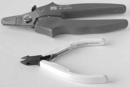
FIG. 6 Cable cutters and micro-cutters
Lindstrom semi-flush micro cutters seem to last the author about ten years before becoming too blunt to use, but cutters with tungsten carbide cutting edges are now available, and should last even longer. Flush cutters are also available, and they are particularly useful when replacing components. Unfortunately, the necessarily smaller included angle of their cutting edges makes them sharper but far less durable (see FIG. 7).
Once the cutting edge has been decided, choose an ergonomically designed handle and springing system if possible - you will use these cutters a lot. If you buy flush cutters, only use them when nothing else will do, or you will wear them out very quickly.
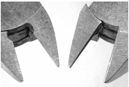
FIG. 7 Note the difference between flush and semi-flush cutting edges
Pliers
Again Lindstrom ''Supreme'', short jaw (21mm). These are for dressing component leads, not for removing your car exhaust!
A pair of short-jawed heavy duty combined pliers/cutters is handy too, but you probably already have a pair for dealing with your car or bike (see FIG. 8).
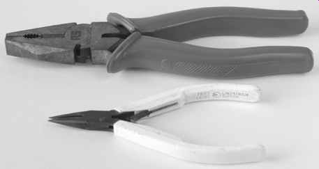
FIG. 8 Heavy duty pliers and micro-pliers.
Occasionally, neither of the previous pliers will do, and you need a pair of long-nosed pliers. They are not nearly as nice to use, and you usually use them because you are being forced into bodging (see FIG. 9).
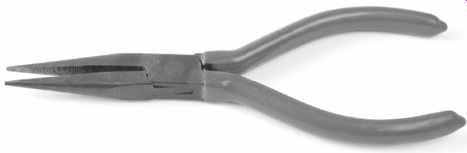
FIG. 9 Long-nosed pliers.
Wire strippers
There are many different sorts of wire strippers, and personal preference is important. The chosen wire stripper should be able to strip cleanly without nicking or cutting the strands of the wire beneath the insulation. The author strips most wire using a scalpel or traditional wire strippers (see FIG. 10).
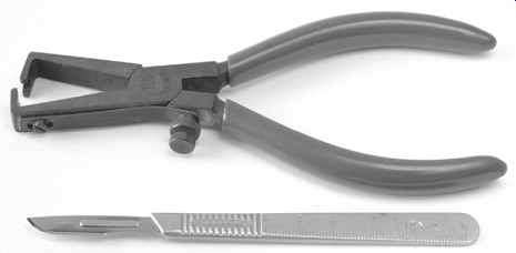
FIG. 10 Scalpel and PO strippers.
If you use wire-wrap wire you must use a dedicated wrapping and stripping tool. These are outrageously expensive for what they are, but nothing else strips the insulation cleanly without nicking (see FIG. 11).
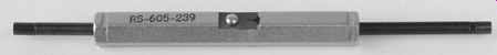
FIG. 11 Wirewrap tool with integral stripper.
Screwdrivers
You really can't have too many good quality accurately ground screwdrivers, and with care, they last forever, so buy the right ones. Stubby screwdrivers are not recommended because they cause inaccurate screwing and damage screw heads. Poor-quality screwdrivers are inaccurately ground and made of inferior metal. The result is that they slip and damage themselves and the screw head. That doesn't sound too bad until you realize that it happens when you have to apply most force -- when the screw is seized. Once you have damaged its head, removing a screw becomes far, far harder -- it's so much easier to avoid damaging the screw head in the first place.
Flat-bladed screwdrivers
You need a 3mm flat-blade screwdriver, often known as an ''electrician's'' screwdriver. An extra-long screwdriver (250mm shaft length) with a 5mm flat blade is extremely useful, and the bigger screwdrivers can be useful too, particularly 7mm. You also need a very small screwdriver; it usually has a yellow handle and is about 60mm long in total, with a blade width of about 1.5mm. Buy two -- they disappear.
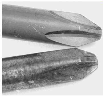
FIG. 12 Note that the Phillips tip (upper) has a sharper angle and is
longer than the equivalent size of Pozidriv tip (lower).
Pozidriv and Phillips screwdrivers
There is a world of difference between these two ''crosshead'' screwdrivers, so you will want to avoid damaging screws and screwdrivers. A Phillips screwdriver has a sharper, more pointed tip, whereas Pozidriv is rather stubbier (see FIG. 12).
Supadriv screws are almost identical to Pozidriv, but have a secondary set of splines between the primary splines. The extra splines enable greater torque to be transferred to Supadriv screws, but they are perfectly compatible with older Pozidriv screwdrivers. Choose the extra-long version with an ergonomic handle as these are useful for computer monitors and aid precise screwing. Sizes 0, 1, 2 are useful, 3 and 4 are a luxury.
European Pozidriv and Supadriv screws are identified by the identifying radial lines between the splines of the screw slots (see FIG. 13).
The author had to tip out his large box of non-BA and non Metric screws and search diligently before finally un-grounding half a dozen Phillips screws. Since Phillips screws are so rare, why are there so many Phillips screwdrivers ready and waiting to mangle Pozidriv screws? Sadly, Pozidriv screws without identifying radial lines are becoming common, particularly on Oriental equipment, so try a Pozidriv screwdriver for fit before a Phillips, even if the identifying radial lines are absent.
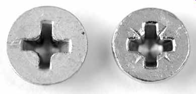
FIG. 13 Phillips (left) versus Supadriv/Pozidriv (right) screw head. Note
the identifying radial lines on the face of the Supadriv head between the splines
Allen (hex) keys and drivers
Buy a good quality set of long arm Allen keys in Imperial and Metric sizes as it is essential to have the correct size. Be careful when using long arm Allen keys. Although they make using chassis punches much easier, they are capable of splitting screw heads made of inferior metal if over-torqued (see FIG. 14).
Be wary of ball-nosed keys - they allow easy access, but unless they are made of excellent metal, the reduced contact area at the head wears quickly and is easily damaged.
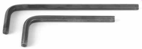
FIG. 14 A 6mm long arm versus normal 6mm Allen key
If you use a lot of Allen screws, you might want to consider buying a set of drivers - they are much faster to use than keys.
Nuts and associated tools
Nuts are undone with spanners or nutrunners, not with pliers! A set of open-ended BA is needed for traditional tube amplifiers, but modern electronics uses metric fasteners. Electronic equipment uses very small nuts, and if the spanner is inaccurately ground, it will slip and chew the nut, so it is essential to use top quality spanners (see FIG. 15).
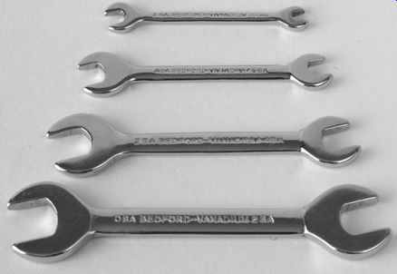
FIG. 15 Selection of BA spanners
Nutrunners are available in all sizes, but one for potentiometer nuts is particularly useful, and prevents visible gouging of front panels by spanners (see FIG. 16).
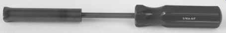
FIG. 16 A nutrunner for potentiometers is particularly useful.
A Bahco 6" adjustable spanner will do nicely for everything else provided it is adjusted to grip the nut as tightly as possible before applying torque, and is sufficiently good to be used for careful roadside repairs of bikes with parts labeled ''Ducati'' or ''Campagnolo''.
A nutlauncher is an incredibly useful tool. Looking like a syringe, when the plunger is pressed, three wire hooks spread out of the far end and grip the nut allowing you to spin it lightly onto the end of an otherwise inaccessible screw. Wonderful! (see FIG. 17).
Once the nut is engaged, a nutrunner or spanner can finish the job.
Sometimes, with the best will in the world, a part will drop off and fall deep inside a heavy amplifier. Rather than lifting the amplifier upside down and shaking it until the part falls out, a magnet is extremely useful for retrieving small steel parts.
Many tool shops sell a tool that is effectively a powerful magnet fitted to the end of a telescopic aerial and packaged to look like a pen (see FIG. 18).
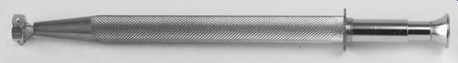
FIG. 17 A nutlauncher makes short work of starting nuts buried deep in
wiring
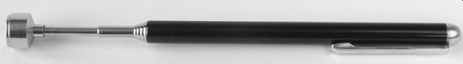
FIG. 18 A magnet on telescopic mount makes retrieval of small steel parts
easy
Scalpel
Scalpels are extremely useful, and the small handle version is best suited for electronics, with either No. 10, or No. 10A blades. Be careful with scalpels - they were designed for cutting flesh. You will find that the blades lose their edge very quickly, so buy blades in bulk, and be prepared to fit a fresh blade the moment you notice a lack of keenness. If you have the option, buy unsterilized blades - they are cheaper, and you don't intend surgery. A guard made from layers of heatshrink sleeving can be made to cover the blade when not in use (see FIG. 19).
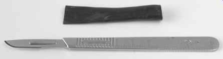
FIG. 19 Scalpel with guard made from heatshrink sleeving
Hot air gun
Tool catalogues stock all sorts of expensive hot air guns for shrinking heatshrink sleeving, but a hot air gun intended for stripping paint works just as well, and is far cheaper. Never attempt to shrink sleeving by heating it from only one side, move the gun continuously around the work to heat it evenly from all sides. The airflow from hot air guns is somewhat indiscriminate, and can easily damage surrounding components such as electrolytic capacitors, but a heat shield of aluminum cooking foil works wonders (see FIG. 20).
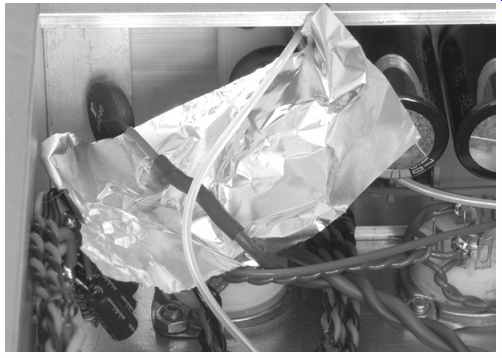
FIG. 20 A temporary aluminum foil heat shield protects other components
when using hot air gun on heatshrink.
Not only does the shield protect other components from the hot air blast, but the turbulence caused by blowing air at the shield means that the heatshrink sleeving is heated evenly from all sides, and shrinks in half the time, which further reduces the risk to surrounding components.
Marker pens and digital cameras
It may sound obvious, but if you label things before you take them apart, life becomes so much simpler. Alternatively, a digital camera is a very useful tool because if you take shots of the work as it is disassembled, you have the perfect guide to reassembly.
Lighting
You can't have too much light to work by. If you are able to have a dedicated bench, try to position it near a window, and fit dedicated lighting over the bench. A 100W fluorescent tube provides plenty of light, but you may find that the increased flicker compared with tungsten is more tiring to your eyes.
If you aren't able to have a bench with dedicated lighting, at least have an adjustable desk lamp that can be positioned over your work. In addition, a powerful torch can be very useful for finding nuts and washers that fall into the depths of an amplifier.
Toolbox
Your precision hand tools should not be thrown in a toolbox together with old spark plugs and oil filters. Keep them in a clean partitioned box of their own and don't lend them to anybody.
Techniques
All AC power wiring generates an external field that can induce audible hum into signal wiring. Heater wiring is the obvious problem, because it will unavoidably be close to sensitive signal wiring, but AC mains and the high-voltage AC to rectifiers can also cause problems.
To save time on assembly and any subsequent maintenance, any fixing screw should be just long enough to use all of the thread in the nut and no longer, and this dictum is particularly important when securing tube bases. Overlong screws on tube bases make heater wiring particularly difficult. Unfortunately, if you decouple your heaters to the chassis at the tube base with 10 nF capacitors (ideal), the necessary solder tags and star washers inevitably require a longer screw. You just have to grin and bear it.
Electromagnetic fields and heater wiring
The electromagnetic field is due to the current flowing in the power wires, which induces currents in any nearby signal wiring. This means that not only are tubes with 12.6V heaters cheaper (contrast the price and availability of NOS 6SN7 with 12SN7), but they're better, too! Halved heater current means 6 dB less heater-induced hum.
Heater wiring is usually taken from a winding on the mains transformer to the nearest tube, and looped through, from one tube to the next, until each tube has heater power. The input tube is the most sensitive stage, so this should be the last in the heater chain, in order that the wiring leading to this tube carries the least current.
To minimize the external electromagnetic field, the heater wire should be tightly twisted. This means that although any given twist induces a current of one polarity, the twists either side of it induce opposite polarity, and so the fields tend to cancel. This twist should be maintained as close up to the pins of the tube as possible, and when one phase of the heater wire has to go to the opposite side of the base and return, as is the case when wiring past an ECC83/12AX7 to the next tube, the wire should go across the base and be twisted as it passes across. Admittedly, the return current is less than the outgoing current, but some cancellation is better than none.
The worst way to wire heaters would take the incoming pair connecting to the two heaters pins from one side, then loop around the opposite side to form a circle of heater wiring around the tube base (see FIG. 21).
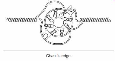
FIG. 21 Poor heater wiring at tube socket: Hum _ enclosed loop area. Note
that the wiring should have been butted up against the chassis edge.
Heater wiring leading to tubes using B9A sockets such as EL84/ 6BQ5, etc., is best twisted from 0.6mm (conductor diameter) insulated solid core wire, which is rated at 1.5A. Octal tubes generally require more heater current, so the larger tags on their sockets can accommodate thicker wire, which could not have been connected to the pins of a B9A socket. When wiring to tubes other than rectifiers, it is useful to use a different color for each phase, and the author has always used black and blue.
When wiring to a push-pull output stage, if the same color goes to the same pin on each tube, then the hum induced within each tube will be the same phase, and will be cancelled in the output transformer. (This argument assumes that both tubes were made by the same manufacturer to the same pattern.) Valve rectifiers such as GZ34 or GZ37 not only have a dedicated 5V heater supply, but they also have the incoming high-voltage AC, so the two should be clearly distinguished. The author uses a red twisted pair for the HT, and a blue twisted pair for the heater.
Twisting wire is easy. Cut equal lengths of wire to be twisted, pair the wires together at one end and clamp them in a vice.
Gently tension both wires equally at the far end, and grip them in the chuck of a drill. Hold the wires reasonably taut by pulling on the drill and start twisting. When the wire begins to accelerate you towards the vice it will have about ten twists per inch. Switch off, and whilst maintaining tension by holding the wire with your fingers, undo the chuck. The wire will now try to untwist, and if allowed to do so suddenly, it will tie itself in knots. Gently release the tension in the wire and release from the vice. You now have perfectly twisted wire.
You will find that it is easier to achieve a perfect twist on longer lengths of wire than short ones, because it is easier to equalize the tension between the wires. Equal tension is important because if one wire is slack compared to the other, it tends to wrap itself around the tighter wire (which remains straight).
For this reason, it is worth twisting 4m or even 6m at a time, but these longer lengths are more easily twisted with a power drill (ideally, a battery drill because they tend to run slower), whereas shorter lengths can be twisted with a hand drill.
Although perfectly satisfactory with commercial sleeved copper wire, the previous method breaks 99.99% pure (fine) silver wire posted down PTFE sleeving. Sadly, silver wire in PTFE sleeving has to be carefully wrapped by hand. Instead of a drill starting a light twist evenly along the entire length of the wire and tightening it, the required wrap must be locally applied with force carefully applied by fingers either side of each wrap, starting at one end of the wire and progressing towards the other.
It is extremely difficult to twist even slightly different gauges of wire together, and you might wonder why this should ever be attempted. The most likely scenario is that a flying lead from a mains transformer primary needs to be taken to a single pole mains switch at the far side of the chassis, return, and then go to the mains inlet. In this instance, current flows from the mains inlet to the switch and returns along an adjacent wire, so it makes a great deal of sense to twist these two wires together to reduce hum induction. Unfortunately, unless the mains trans former has very long leads, it is unlikely to be able to reach to the mains switch and back, so you are forced to twist it with a wire from your stock that is almost certainly slightly different.
When you do this, one wire almost invariably remains almost straight, and the other wraps around it. The solution is to gently tension the wire that wanted to wrap, and wrap around it the wire that wanted to be straight. This method is a little fiddly, but enables two different wire types to be twisted evenly, thus ensuring cancellation of hum.
Although solid core wire perfectly retains a tight twist, multi core wire tends to separate, reducing cancellation. The way to avoid this problem is to pre-tension each wire equally by individually twisting it in the opposite direction of the final twisted pair. Without releasing each wire's pre-tension, grip the wires in the vice and chuck, and twist them together. The effect of this is that as the wires are twisted together, the pre-tension is relieved, so there is no latent force trying to separate the final twist. Although this method works very well, solid core wire retains the tightest twist and can be positioned more precisely, so it is superior for heater wiring.
Electromagnetic fields decay with the square of distance, so heater wiring runs should be as far away as possible from signal circuitry as possible, and only come up to the tube at the last possible moment and in the most direct manner possible.
Valve sockets should be oriented so that the pins receiving heater wiring are as close to the chassis wall as possible, and heater wire should never loop round a tube (except for rectifier tubes, where hum is not an issue).
Electrostatic fields and heater wiring
The electrostatic field is due to the voltage on the wiring.
Heater wiring should be pushed firmly into the corners of the (conductive) chassis, since the electrostatic mirror at the corner tends to null some of the electrostatic field. Heater wiring must not run exposed from one tube to the next, but should return to the corner of the chassis to re-emerge at the next tube. These strictures mean that good heater wiring requires considerable time/cost, so modern commercial amplifiers sometimes skimp on the quality of their heater wiring, yet good wiring allows an RIAA stage to use AC heaters.
AC heater wiring should be connected to the transformer in a balanced fashion. Unfortunately, heater wiring must have a DC path to HT 0V in order to define the heater to cathode voltage, and this can be achieved in various ways (see FIG. 22).
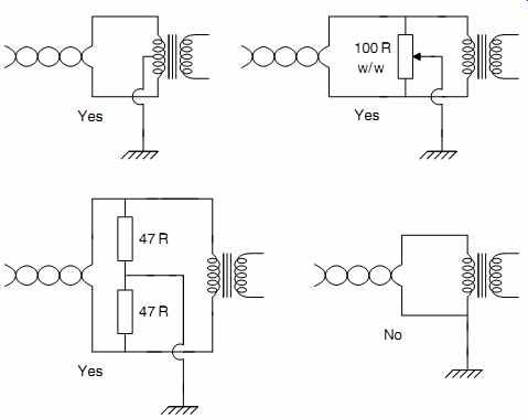
FIG. 22 Defining DC heater potential.
The worst way to define the DC path is simply to connect one side of a transformer winding to 0V. This ensures that one phase of the wire induces no hum, whilst the other phase induces maximum hum.
The ideal way of defining the DC path is to use a transformer with a centre tap on the heater winding, but if this is not available, fixed or variable resistors can be used to derive a midpoint. Accurately matched resistors used to be rare, so a variable resistor known as a humdinger control used to be fitted, and adjusted for minimum hum. Once an LT midpoint has been derived, and connected to HT 0V, each wire has equal voltage (but opposite phase) hum, and the electrostatic fields tend to cancel.
The previous cancellation cannot be perfect, and for ultimate reduction of heater-induced hum, we should screen the heater wiring with braid or thin-walled aluminum tubing (available from modeling shops), and/or use DC heater supplies. Even when using DC heater supplies, it is worth treating the heater wiring as if it were carrying AC, as this will ensure that the finished project has no heater-induced hum. The output of a DC heater regulator has virtually no AC present, so the LT 0V can be connected directly to the HT 0V.
Heater wiring is the first piece of wiring to go into a project, thereafter, it is obscured by signal wiring. Once all the other wiring is in place, it is impossible to replace the heater wiring, so it must be installed correctly (see FIG. 23).
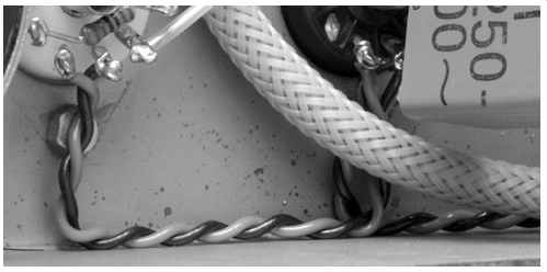
FIG. 23 Good heater wiring is pushed deep into the corners of the chassis
and maintains its tight twist all the way to the tube socket.
Because it is so difficult to make changes to heater wiring, it is a very good idea to immediately do the mains wiring and test it all by plugging all the tubes in and making sure that they glow.
Quite apart from saving tears, seeing a set of glowing heaters gives an important psychological boost before tackling the more complex wiring.
Mains wiring
Mains wiring should be as short and direct as possible because the wire's insulation is often quite thick, so it cannot be twisted well. Mains wiring inevitably generates considerable electro static interference fields, so put the mains switch near the back panel, and if necessary, add a mechanical linkage to bring its control to the front.
Modern semiconductor equipment sleeves all exposed mains wiring with rubber or PVC sleeving such that it is moderately safe to rummage inside a piece of powered equipment. Valve amplifiers operate on such high voltages that it is never safe to rummage in powered equipment, and even unpowered equipment should be approached with caution. Safety is therefore not greatly improved by sleeving mains wiring, but it is still good practice to sleeve mains wiring with heatshrink sleeving or purpose-made rubber boots to fit over IEC sockets or fuse holders (see FIG. 24).
The only approved 3-pin domestic mains connector is the IEC plug/socket, which is familiar to many as the connector fitted to computers and electric kettles. They are available with integral fuseholders which allow much safer construction and are thoroughly recommended.
The mains connectors used on classic tube amplifiers are, without exception, outrageously dangerous.
Mains switching
To switch a piece of equipment off, all we need to do is to break the circuit from the source of power. A mains switch could therefore equally well be inserted in the live or neutral wire, and still perform the job, and this is known as single pole switching.
However, a switch in the neutral leaves all internal mains wiring live and constitutes a shock hazard within the equipment. Single pole switching should therefore always switch the live circuit to minimize shock hazard.
Double pole switching switches both the live and the neutral, and ensures safety even if the live and neutral wires are reversed.
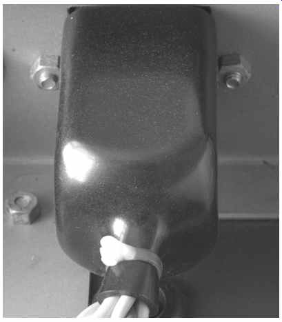
FIG. 24 IEC input connector sleeved with insulating boot
CD players often use non-polarized ''shaver'' plugs on their rear panels, which allow live and neutral to be reversed, so they commonly use double pole mains switching.
Where there is no possibility of live/neutral reversal, single-pole switching is safer, and more reliable, because failure of the switch ensures a break in the live connection to circuitry. A double-pole mains switch has twice as many contacts to fail, and if the neutral contact fails, the equipment could appear to be safe, even though the mains wiring is connected to live mains, and still constitutes a shock hazard.
Fuses
A fuse is a piece of fine wire having resistance, connected in series with the circuit to be protected. If excessive current passes through the wire, it heats in accordance with I^2 R, and heats sufficiently that it melts, or ruptures. A fuse is a single pole switch, and should therefore be connected in the live wire, before any other circuitry, such as a mains switch.
Clearly, the wire in a fuse must lose some heat to its surroundings, so a mild overload could allow much of the heat that should have melted the fuse to escape, whereas a short duration gross overload cannot lose so much heat and ruptures the fuse quickly.
As an example, a 13A fuse to BS1362 (as fitted to a UK 13A domestic plug), ruptures in 0.4 s at 100A, but needs 10s at 50A.
To calculate the mains fuse rating, the total power consumption of each individual load on the mains transformer should be summed to find the total load taken from the mains. The current drawn from the mains may now be found, and the fuse rating should be the next rating above this. This calculation contains many sweeping assumptions and approximations, but fuses are not accurate either, so the method will be found to be satisfactory.
Some equipment, particularly if it includes a toroidal mains transformer, draws a large inrush current, but its working current is much lower. To cope with these requirements, anti surge or timed fuses are available, which can withstand short overloads. These fuses usually have their values preceded by a ''T'', so T3.15A refers to a timed 3.15A fuse.
Protecting each output of a multiple winding mains transformer is difficult for the following reasons:
-- Fuses are very rarely fitted to HT supplies because they offer only very limited protection to the output tubes. In a Class A amplifier, the output tubes are usually run at precisely their maximum anode rating, so a doubling of anode current quickly causes damage. However, a fuse may not blow with an overload as small as this, so little protection is offered.
Fuses can be fitted to Class AB amplifiers, and are advisable for OTL designs, but their non-constant resistance can cause distortion.
-- Fuses are never fitted to heater supplies because heater circuitry is normally so simple as to not warrant a fuse. Failure of heater supplies often causes damage elsewhere in a DC coupled amplifier, as tubes switch off and anode voltages rise to the full HT voltage.
-- Grid bias supplies to output tubes should never be fused because failure of this supply would immediately destroy the output tubes.
For these reasons, most tube amplifiers do not have any fuses other than a fuse on the primary of the mains transformer.
Glass-bodied fuses should never be used to protect high-voltage circuits such as AC mains. A short circuit causes the fuse to rupture instantly and vaporize, thus depositing a conductive metal film on the inside of the glass which continues to pass a small current, but heats the glass. If glass is heated sufficiently, it becomes a conductor in its own right, and so the fuse has failed to protect the circuit. Fuses suitable for high-voltage use have ceramic bodies filled with sand to prevent the creation of a continuous conductive film.
To prevent tampering, mains and high-voltage fuseholders accessible from the outside of the chassis should require a tool to release the fuse.
Class I and Class II equipments
Class II appliances have all hazardous voltages ( >50V) double insulated from contact with the operator, and use a 2-core mains lead. Double insulation requires two insulating barriers, one of which may be air, each independently cap able of withstanding the shrouded voltages and protecting the operator. It is possible to make a Class II appliance that has exposed metal, but rigorous testing is required to ensure that the appliance meets the full technical standard. A symbol consisting of two concentric squares signifies double insulation.
Class I appliances require only one layer of insulation from hazardous voltages, but this layer must be totally shrouded by a conductive layer bonded to mains ground via a low-resistance path. It is far easier to make equipment that conforms to Class I than Class II, so amateur equipment should always be built to the Class I standard to ensure safety.
These classes of insulation do not merely apply to the appliance, but also to the mains cable from the wall socket. Since domestic power leads cannot conveniently (and cheaply) include an grounded conductive sleeve, the cable is normally double insulated, so a single layer of insulation over each conductor is insufficient, which is one reason why three-core mains cable has a thick external sheath.