In the previous Section, we looked inside test equipment to see how it worked and to understand its design limitations. We are now in a position to move on, so this Section is concerned with using test equipment to bring a device to a usable state.
There are three stages of testing:
-- Safety testing: Will the device under test (DUT) endanger the user?
-- Functionality testing: Does the DUT work as it should?
-- Faultfinding (hopefully optional): Having established that the DUT doesn't work correctly, what needs to be fixed? Rather than scribbling results on scraps of paper and losing them, you will find it extremely useful to keep a logbook of your tests. The logbook should include:
-- Circuit diagrams of the circuit tested
-- Diagram or description of how the test was undertaken
-- Results of the test
-- Subjective comments on the test (Were the results expected?)
-- Date of the test, and test equipment used
-- If any of the test data has been saved to computer (spread sheet, photograph, etc.), include the file names.
The purpose of the logbook is to enable you to look back and know the results of a test, rather than scratching your head and saying, ''I'm sure I've tested this before. ''
Safety
Before we go any further, we should understand that there is no such thing as perfect safety. Everything we do, from crossing the road to eating a chicken sandwich carries an element of risk.
Lawyers currently enjoy a climate where ludicrous damages are awarded to clients who failed to take any responsibility for their own safety - of course a cup of hot coffee will scald you if you spill it over yourself! The dangers of hot liquids are well known, but the dangers of tube electronics are not as well known as they used to be, and even professional engineers can become complacent about putting their hands inside live equipment.
The aim of this section is to point out some of the more common dangers and show simple ways by which risk may be reduced.
Nevertheless, it is impossible to cover all possible situations, and this is why electronics workshops forbid work on live equipment unless two people are present. In that way, one person is ready to rescue the other in the event of an accident. If you have a more experienced friend, it would be a good idea to emulate commercial practice by asking them to attend when live working is necessary and to check your work beforehand. Ensure that they know how to switch off the power quickly.
An understanding of the physiological effects of electric shock, whilst somewhat ghoulish, serves to underline why safety is so important.
How an electric shock can be received
The best way of avoiding electric shock is to understand how it can be received.
The electricity supply leaving the wall socket in your home is a very good approximation to a pure Thevenin source of zero resistance, with one side of the source connected to ground. In this instance, we do not mean ground in its purely technical sense, the supply really is connected to the planet Ground. You and I perform most of our activities on the surface of the ground, and we are therefore electrically connected to it, albeit usually by a high-resistance path. We can improve our electrical contact to ground by standing barefoot on a damp floor, or by firmly gripping something that is electrically bonded to ground.
Manual activities like hobbies are precisely that, manual. They involve our hands going inside objects, and touching them.
Humans generally possess two hands, and so what is more natural than to put both hands inside a piece of equipment? The scene has now been set for one hand to be holding the (grounded) chassis of a piece of equipment, whilst the other is moving around and accidentally comes into contact with live mains.
Look at your hands. They are on the ends of your arms, and your arms are joined to your torso. Trace a line from the fingers of one hand to the fingers of your other hand, without the line leaving your body. Note the path.
The easiest path for an electric current to flow from one hand to the other crosses near the heart. Similarly, a shock from one hand to ground passes near to the heart.
The effects of electric shock
The main danger from electric shock is fibrillation of the heart.
The heart normally beats at a slow pace regulated by electrical impulses from the brain. If we apply 230V 50Hz to the heart, it pulses quickly, the flow regulating tubes do not operate correctly, and no blood is pumped, leaving the brain to die of oxygen starvation in about 10minutes. A sustained current of 20mA through the heart is sufficient to cause fibrillation, resulting in the adages, ''20 mills kills'', and, ''it's the volts that jolts, but the mills that kills''.
A sustained current might not kill, but could cause irreversible injury due to the heating effect of the current. RF burns are notorious for this, and can result in limbs having to be amputated to prevent the spread of gangrene. A lower sustained current may cause injury from which the victim does recover. Eventually. Skin grafts may be necessary.
A current of 20mA results from a 230V supply connected across a resistance of ~11 kOhm. Very few power supplies have a source resistance as high as this, so shock current is determined primarily by skin resistance, and a shock from a puny transformer delivering 230V is just as dangerous as the shock received directly from a 100A mains feeder. Skin resistance is reduced by damp hands, and standing in the rain in a puddle of water lowers resistance further.
All of the above considerations refer to the direct consequences of electric shock, but do not consider secondary effects. A minor shock that causes the victim to lose their footing and fall over could be fatal if they happen to be standing on a ladder 30 ft above concrete. Another possibility is that the reflex muscle jerk in reaction to the shock could cause the victim to throw them selves through a glass window and bleed to death.
Even after a minor electric shock, the victim will be confused and disoriented, and shock in its full medical sense is a possibility. Shock kills.
Burns
Although the primary hazard of electrical equipment is shock from high voltages, it should be realised that low voltages can be just as hazardous. A low-voltage/high-current DC supply will have a large, low ESR, reservoir capacitor capable of delivering many amps of current into a short circuit.
Rechargeable batteries are even more dangerous because they are capable of sourcing substantial current for a significant time. (Think about it, a car starter motor requires 100A, or more, for several seconds.) These batteries are not merely capable of burning, they can vaporize metal bracelets, watch straps, and tools. Do not wear jewelry whilst working on live equipment.
Avoiding shock and burns
It should now be obvious that electric shock is potentially lethal, burns can be serious, and that both must be avoided at all costs.
Provided that you have made, or modified, your equipment carefully, there will be no exposed voltages, and all metalwork will be grounded, resulting in a very low risk of shock. The danger arises when you deliberately remove the safety covers, and start testing the equipment with power applied.
Some authorities suggest that you should always work on live equipment with your left arm behind your back, so that any shock received will not pass from arm to arm across the heart.
Whilst it is true that this will reduce the severity of the shock, it tends to increase the risk of receiving a shock.
The best way of improving safety is to think about safety, and to think about what you are doing. It might seem obvious to think about what you are doing, but for most of our lives we think about many things at once. For instance, when driving, are you thinking only about driving, or are you actually thinking about what you are going to say to your boss when you arrive late for work, and when is that idiot in front of you going to turn into the junction, and isn't that a rather attractive male/female/alien over there by the bus stop? Thinking about what you are doing means not working late. Do not attempt to test a newly completed project at 11:30 at night; you will not be alert and could damage the project and/or yourself.
Electrical safety testing
Consumer electronics falls into two safety categories. Class I has an grounded conductive barrier enclosing the high voltages, whereas Class II has two independent insulating barriers enclosing the high voltages. Many appliances are actually a combination of the two categories because although the appliance could be Class I, the mains lead is invariably Class II.
Class I relies on quickly blowing the mains fuse, whereas Class II relies on undamaged barriers. Commercial safety testing therefore consists of a careful inspection by a competent person to check barrier integrity, plug wiring, and that the correct fuse has been fitted. These visual tests are backed up by electrical tests.
A safe piece of Class I equipment has an grounded conductive barrier with no conductive path to any of the enclosed high voltages and a sufficiently low-resistance path to ground that any contact to the mains line causes such a large current to flow that the mains fuse ruptures quickly. Electrical safety can there fore be tested by measuring leakage current flowing from the barrier and by measuring the resistance from the barrier to the ground pin of the mains plug. Since many pieces of equipment have to be tested, it makes sense to have a dedicated instrument to make the tests.
Portable appliance testers
Portable appliance testers (PAT) are simply specialized resistance and leakage testers with appropriate connectors for quickly testing mains portable appliances. The emphasis on the word ''quickly'' is important because even a small business could have hundreds of appliances that must be tested for safety each year. In order to cause minimum disruption each appliance must be tested quickly and unambiguously, and a record must be made of the test. Older PAT testers simply make the required pass/fail electrical tests, whereas newer testers guide the operator through the test procedure, make the measurements, give pass/ fail status, and log the data together with the appliance's identification (often a bar code) for later download to a computer.
Because the newer testers make it much easier to comply with the various safety regulations, there are plenty of older, manual testers available in perfectly good working order, and you might want to acquire one (see FIG. 1).
As part of a Class I test, a PAT tester measures ground loop resistance (resistance from the chassis to the ground pin of the plug) by passing a considerable current, sometimes as much as 25A. The purpose of such a large test current is to detect frayed ground connections. A single strand would still have low resistance because it would be very short, even though its cross-sectional area would be small, so a simple resistance measurement could not detect the problem. However, the PAT tester deliberately seeks to rupture such frayed connections, which subsequently fail the resistance test. At the same time, the tester applies a high voltage (>500VRMS) simultaneously to the line and neutral terminals and monitors leakage current returning through the ground circuit. Do not touch the appliance whilst the PAT tester applies this dangerous voltage.
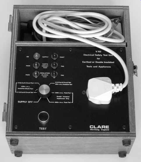
FIG. 1 Older PAT testers are still perfectly capable of making important
safety tests.
Be aware that PAT testers are not invincible, and can develop faults just like any other piece of equipment. If you rely on a tester to determine safety of other equipment you have to be certain that the tester works correctly and that you are operating it correctly. Most testers include operating instructions and a selection of ''faulty'' test jigs that should be regularly tested to verify correct operation of the tester. You might question the validity of using a second-hand tester, particularly since it will almost certainly be sold without any warranty of fitness for purpose. Provided that you are not using it to assist in selling goods or services, the question is not whether the tester perfectly meets all the latest safety regulations, but whether it reduces risk compared to not being able to test at all.
Functionality testing
The word ''testing'' implies a degree of ambiguity about the results of the test; if we knew that our new amplifier was going to work perfectly from the moment that it was completed, we would not need to test it. However, we know that wiring mistakes can be made, and that components could be faulty, so we test our amplifier carefully.
Second-hand equipment versus freshly constructed new equipment
Both types of equipment should be treated with a great deal of suspicion and apprehension. The only sensible state of mind when first switching on is controlled fear.
Quite clearly, a piece of newly constructed equipment will be switched on at some point, but some old equipment may be so dangerous, or riddled with faults, that it should never be energized, other than applying kinetic energy to throw it into a skip.
The state of old equipment can easily be determined by looking at the components.
Things to avoid are:
-- Wire insulated with rubber and covered with cotton
-- Enormous resistors marked with tip, body, and spot color codes
-- Electrolytic capacitors with bulges in the rubber surface supporting the tags
-- Previous evidence of fire
-- Insulating tape anywhere!
Vintage radios may incorporate any or all of these features but may still be of value to someone, so try to check with someone else before destroying them [1].
For a professional, the worst possible sign is previous modification by an amateur. The professional then has to decide whether or not the amateur knew what they were doing. What is the effect of their modification, and was it done competently and safely? For this reason, modified equipment is usually worth less than unmodified equipment, so bear this in mind before you embark on modifications.
Second-hand equipment can often be dated by the date on the electrolytic capacitors. If it is over 30 years old, it is likely to need major refurbishment even to make it work, so this should be taken into account if you are considering purchase.
The first application of power
Before applying power for the first time, the following ''Ten Commandments'' should be observed:
-- Inspect the ground bonding. Does the chassis appear to be properly grounded? (Does an undamaged ground wire make a good connection to the chassis? If a tag is used, is it tightly bonded with a star washer between it and the chassis?)
-- When measured, is the resistance from the ground pin of the mains plug to the chassis of the equipment significantly less than 0.5 Ohm? (Preferably use a PAT tester.)
-- With the power switch on the equipment (if fitted) switched on, is the resistance from the other pins of the mains plug to the ground pin infinite? (Preferably use a PAT tester.)
-- Does the mains cable look safe? i.e. not frayed, perished, cut, or melted by a soldering iron.
-- Is the mains plug wired correctly?
-- Does the plug grip the sheath of the cable correctly?
-- Does the plug look safe? i.e. no cracks, chips, dirty pins, etc.
-- Is a fuse of appropriate rating fitted? (It is unlikely that the fuse rating should be greater than 3A.)
-- Does all the internal wiring of the chassis look secure?
-- Is the chassis clear of swarf and odd off-cuts of wire? Turn it so that bits can fall out, and give it a really good shake, whilst blowing vigorously into the chassis to free small parts. Alternatively, if it is too heavy to lift and shake, use a 1/2" paintbrush and a powerful vacuum cleaner to remove debris.
If all appears to be well, you can move on to the next stage.
The author always assumes that when power is applied, the amplifier will explode, or at the very least, catch fire. It does not, therefore, make sense to stand with your face over the amplifier, or to place it in the middle of a pile of inflammable debris. Power amplifiers should have dummy loads, or ''disposable'' (cheap) loudspeakers should be connected across their outputs.
The safest way to test a tube amplifier is in stages. Many amplifiers use a tube HT rectifier, so if this is removed, the mains transformer and heaters can be tested before applying HT. Silicon HT rectifiers make disabling the HT a little harder, and require the AC to the rectifiers to be removed. If this is a new amplifier, you will have planned ahead by testing the heaters before doing any other wiring (that way, the heater wiring is easily accessible should a fault surface).
The heaters in indirectly heated tubes take a moment before they begin to glow, so connect a meter across the heater supply to give an instant indication of whether the heater supply is present, and leave the meter in a clearly visible position. If you have a variac, you can apply power gently, and if the meter monitoring the heater supply doesn't immediately respond when you advance the variac from zero, back it off and investigate.
The advantage of using a variac is that even a short circuit across the heater supply would be unlikely to cause damage because you would spot it before applying significant voltage.
If you don't have a variac, retire to a safe distance and apply the power in silence. This way, you will hear any unusual noises, such as the crackles or pops that presage destruction.
If the meter monitoring the heater supply responds appropriately and nothing untoward happens, move a little closer and sniff the air. Can you smell burning? Are there any little wisps of smoke leaving the chassis? If all still seems to be well, look closely at the heaters -- they should be glowing, but should not have hotspots (see FIG. 2).
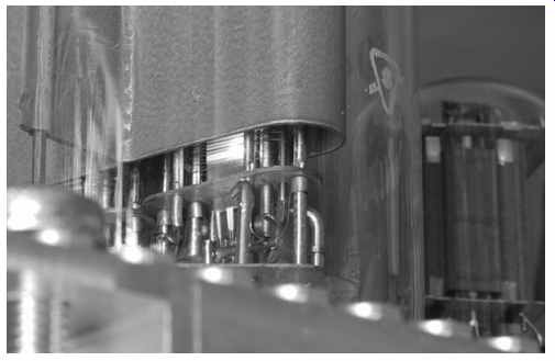
FIG. 2 This 13E1 had a nasty cathode hotspot, so it was rejected without
HT ever being applied to its anode.
Leave the tubes to warm for a while. Ideally, at first switch-on, unused tubes should warm their heaters for 30minutes before HT is applied. However, even 10 minutes gives time for your nerves to calm down and for you to consider your next step.
Having left the heaters glowing for a while, check the temperature of the mains transformer, which should be cool. Switch off power, and unplug the mains lead, leaving it in plain sight. If the amplifier has heater regulators, carefully inspect them for signs of damage, but be careful near the tubes, which will still be hot.
If nothing has been damaged by warming the heaters, it is time to test the HT as well as the heater supplies. Depending on the complexity or output power of the amplifier, this might be done in a number of ways:
-- Classic amplifiers simply need their HT rectifier to be inserted and the amplifier to be switched on.
-- Modern amplifiers often use silicon HT rectifiers. Suddenly applying peak HT to an electrolytic that has sat quietly on a shelf for several months is unkind. Use a variac to bring the voltage up gently over 20 seconds, or more.
-- If the amplifier has separate HT and heater transformers, it is worth powering the HT transformer from a variac and testing the HT before completing the final wiring that connects the transformer to the amplifier's internal mains distribution.
Individual circumstances will determine how you test the HT for the first time, but if it's possible to do it gently, then do so -- it minimizes the amount of smoke.
Having chosen your method of testing the HT, apply power.
Listen. Are the loudspeakers making any unusual noises? In this instance, silence really is golden. Is the HT voltage correct? If the HT voltage is correct, then it is highly likely that the circuit is working as it should, and you may breathe a quiet sigh of relief.
If you are testing a newly built power amplifier, there is a 50/50 chance that global negative feedback taken from the loud speaker output will turn out to be positive feedback, and the amplifier will become a power oscillator. Often, before oscillation starts, a quickly increasing hum will be heard from the loudspeaker; if the amplifier is switched off at this point, only a brief shriek of oscillation will be suffered.
If, at any point, something untoward happens, switch off immediately at the mains outlet and unplug the mains plug.
Usually, if anything is wrong in an electronic circuit, heat is generated and components are burnt, so look for charred resistors or wires. Once the burnt parts are found, the fault is usually blindingly obvious.
If you switched off hurriedly because of a burning smell, what sort of a smell was it? Old equipment will often be dusty, so a slight burnt dust smell is normal. Bacon smells are sometimes produced by burning mains transformers, whereas burning PCBs often smell like underground railway stations with a hint of charcoal, but burning wiring gives off an acrid smell.
If the amplifier appeared to be satisfactory, leave it switched on for a minute or two longer, whilst keeping an eagle eye on everything; particularly output tubes, which should not have glowing anodes, or purple and white flashes. Switch off and sniff the internals closely for unusual smells. Some engineers go one step further and touch components with their finger to check temperature, but this is not recommended as some HT may still be present. If all seems well, the amplifier can be switched on again, and all the DC voltages carefully checked, if it still looks good, then it probably is good.
If you have a variac, now is the time to check how well the amplifier responds to mains voltage variations. UK mains voltage is specified as being 230V +10% -6%, but this is simply a paperwork ruse to enable harmonization with the rest of the European Union. In practice, the voltage at your wall socket is the same voltage it always was. Nevertheless, although mains voltage variations are smaller than they used to be, the voltage does vary, and could cause problems. Use the variac to check that capacitor voltage limits are not exceeded when 253V is applied, and that regulators don't become excessively hot.
Similarly, drop the mains voltage to 216V and check that regulators do not drop out. These two tests are quite severe, and if you know that your mains voltage is more stable, you might decide to adopt a less stringent test.
For the first few weeks of service, a new amplifier should be watched like a hawk for signs of incipient self-immolation and should not be left unattended when switched on.
Fault-finding
Unfortunately, we all have to do some faultfinding at some time or another, either because we made a design or construction mistake, or because we need to repair an amplifier that has failed due to old age. Before we dive into details, we should ask one very important question, ''Did it work once?'' If it worked once, you are looking for a faulty joint or component, and the resistance range of your multimeter will prove invaluable for finding carbon resistors that have ''gone high'' in value from age, or capacitors that have become leaky. If the circuit is freshly built, then you are probably looking for a wiring error.
Individually test each component
One way of faultfinding an amplifier might be to remove each component individually and test it:
-- Resistors: Check claimed value against measured value using the resistance range of a DVM.
-- Capacitors: Use DVM on resistance range to check for leakage, then check claimed value of capacitance against measured value on the capacitance range of the component bridge.
-- Inductors: Use DVM on resistance range to check continuity, then measure inductance on the component bridge.
-- Valves: Use tube tester to compare with test data on the tube tester.
-- Semiconductor diodes: Use diode check range on DVM to check for open circuit when reverse biased, and correct for ward drop when forward biased.
-- Transistors: Use a semiconductor analyzer to check functionality and compare measured hFE with manufacturer's data.
Even better, use a curve tracer to plot its full characteristics.
-- Transformers: Connect to an oscillator and check each output with an oscilloscope to verify functionality and turns ratio.
You will notice that the previous tests assume that you have a great deal of expensive test equipment and full manufacturer's data to check your measurements against. We only remove and test each component fully when:
-- We know no better
-- All else has failed.
The very best piece of test gear is your brain. It's readily available, so it seems a shame not to use it.
DC conditions
The most common fault is a lack of signal, or reduced signal accompanied by gross distortion.
Most faults can be found very quickly by measuring the DC conditions of the circuit. For a well-designed circuit to be observably faulty, the DC voltages usually need to be very wrong. Consequently, checking the measured voltages against the design voltages quickly pinpoints the fault - it's easy to confuse resistor multiplier band colors. Mark the measured voltages (lightly, in pencil) on the circuit diagram. This usually has the effect of making the fault appear blindingly obvious.
Sometimes you will not have the circuit diagram of the amplifier, let alone its design voltages. No matter, there were very few variations in classic tube circuitry, and their circuits were so simple that it is not difficult to produce a block diagram of the amplifier. At this point, consider how you would design an amplifier using those tubes, and look for similarities in the actual amplifier. It should now be possible to obtain a rough idea of what sensible voltages might be, and these can be checked against the faulty circuit. Modern amplifiers are likely to be more complex and contain transistors, so they may require careful circuit tracing. Fortunately, there are now so many websites carrying information on tube audio that it is highly likely that the information you need is somewhere on the web -- you just have to find it. If you can't find a complete circuit diagram, tube data sheets are a good second best because they give maximum ratings, typical applications, and pin connections.
A calculator is invaluable for calculating currents through resistors, and generally deciding whether measured voltages make sense.
Do not implicitly believe what your digital voltmeter tells you.
Even the standard 10 M-ohm input impedance of a digital volt meter loads some circuits, particularly the grid circuit of cathode followers or circuits with grid battery bias. The author was once convinced that audible distortion was due to the DC conditions within a tube active crossover, and a digital volt meter appeared to confirm the theory, but a tube voltmeter with 90 M-ohm input resistance measured a more correct value, and the distortion finally turned out to be due to an intermittently scraping voice coil in a loudspeaker.
Blocks and attitudes
Imagine that you have just been told that the Hi-Fi isn't working. If you have simultaneously been plunged into darkness, you assume that the power has failed. Alternatively, if you look at the CD player, and see that its display isn't counting, despite you having pressed ''play'', you conclude that either the player or the CD is faulty, and you try another CD. In each instance you are breaking the system down into blocks and checking each block. Exactly the same technique can be applied to internal electronic faultfinding.
A power amplifier example
Imagine that you switch the amplifier on, play a CD, yet nothing comes out of the loudspeakers. You look at the amplifier and observe that the heaters are glowing. You have just eliminated the mains lead and associated fuse. Next, it could be that the amplifier simply isn't receiving any signal, or that the loudspeakers have become disconnected. Of course, the loudspeakers could be faulty, but most loudspeakers contain two drive units, and possibly more, so for both loudspeakers to be faulty, you require four simultaneous failures. That just isn't likely, even if you had a very good party the night before. Similarly, although the leads to both loudspeakers could both be faulty, it's unlikely. It is far more likely that we are looking for a single fault that affects both channels.
We ought to check that a signal is reaching the amplifier. We could try a different source, or if the CD player has an integral volume control (and some do), we could plug it directly into the power amplifier and increase the volume gently from zero.
Assuming that there is still no sound, we know that we are looking for something that is common to both channels and that's usually the power supply. We know that the heaters work, so that narrows the investigation to the HT supply. There haven't been any nasty smells, explosions, or fizzing noises, so something has died quietly and completely. If a component was merely poorly, we would have had low HT, and the amplifier would have produced some sound, although probably very distorted.
All HT rectification is full-wave, so it is unlikely that both diodes have failed, unless it's a tube rectifier, where the common cause for two diode failures would be the heater, but we checked that all the heaters were glowing. We can lose HT either because something in series has failed open circuit, or because something has failed short circuit down to 0V. If an HT capacitor had failed short circuit, it would have announced its failure with some noise (explosion, fizzing, distorted sound plus hum from the loudspeakers). It is far more likely that a series resistor or choke has failed.
Now that we know what we are looking for, we can switch off, unplug the amplifier from the mains (leaving the plug in plain view), take the covers off and (carefully) investigate. There could still be charged HT capacitors, so it's worth using the DC voltage range of your DVM to check that they are discharged, but be careful when probing inside even a notionally unpowered amplifier, more than one piece of equipment has been destroyed by the slip of a probe. If capacitors still retain charge, a 10 kOhm wirewound resistor is a handy way to discharge them safely (see FIG. 3).
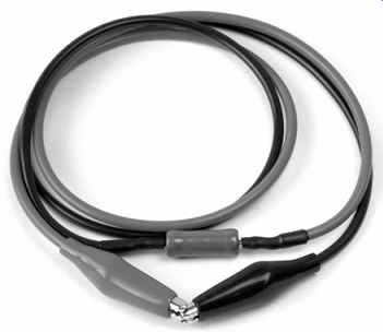
FIG. 3: A 10-kOhm 6W resistor with leads and insulated crocodile clips is
very handy for safely discharging capacitors
Quite apart from the fact that a capacitor's residual charge could give you a nasty surprise, it would interfere with any attempt at resistance measurement by your meter. Bear in mind that electrolytic capacitors suffer badly from dielectric absorption, so leave your meter monitoring their voltage whilst discharging.
You must pull the capacitor's voltage to well below 1V, and this can easily take 20 seconds. Assuming that all the capacitors are discharged, we can use the resistance range to check the HT choke and series HT resistors, and find the problem quickly.