Some Common Tint Problems:
Many color TV manufacturers now have deluxe models featuring automatic fine-tuning (AFT) to accurately adjust the fine tuning electronically, and automatic chroma gain control (ACC) to hold the color saturation nearly constant.
One annoyance still remains in the frequent changes of hue that are not caused by the receiver. You undoubtedly have seen the ghastly purple or sickly green faces that were produced when the program source was changed from live newscasts to filmed commercials, from old movies to taped commercials, or from one TV channel to another.
This is a many-sided problem with no single source or cure. Some cases are the result of the different color rendition of various brands of slide or movie film, while others may be due to an unbalance of the three primary colors in the TV camera.
These broadcast shortcomings can be minimized, but not eliminated, by receiver adjustments.
Color hue changes caused by variation in the phase of the transmitted burst signal usually can be restored by repeated use of the hue control on the receiver. However, this activity is often accompanied by a marked increase in the viewers blood pressure.
Some system to adjust the hue automatically is very desirable. At first thought, one solution would be to use a phase detector to electronically maintain a constant hue. Unfortunately, there is no standard to compare the burst phase against.

Fig. 1 (A) Circuit board and components for the Magnavox ATC circuit.

Fig. 1 (B) Block diagram of the ATC circuit.
How Magnavox's ATC Works
One practical answer to this distressing hue problem is found in the Magnavox color receivers that use the T940 chassis. The manufacturer calls these models Total Automatic Color (TAC) since they have AFT, ACC and ATC (automatic tint control). Their ATC circuit changes all the yellow and red areas of the picture to an orange that is acceptable as skin color. Thus, skin color that ordinarily would look slightly green or purple will be rendered as orange so long as the ATC is switched on.
The ATC circuit board has no tubes, but uses diodes and transistors. It is mounted on the tuner mounting assembly and is completely shielded. A picture of the component locations and a block diagram of the circuit are shown in Fig. 1.
The amount of ATC correction is selected manually by a three-position switch on the front panel which provides OFF (no correction), PARTIAL-correction and FULL-correction. The ATC circuit is inserted electronically between the moveable arm of the color control and the demodulators. There are two parallel paths for the chroma signal: one to the emitter of QA4, the chroma amplifier transistor, that produces an amplified, but not phase-inverted, signal at the collector. The phase correction path is through the Red and Yellow gate transistors, with their combined outputs going to the base of QA4. Since the gate transistors invert the signal, and the signal at the base of QA4 is inverted again before appearing at the collector, both of these signal paths are in-phase at the collector of QA4.
Fig. 2 illustrates a color wheel that shows the hues obtained when a chroma signal of the phases listed is compared (in a demodulator circuit) with the phase of the burst signal. Magnavox has chosen a chroma signal with a phase of 57° to give the desired reddish-orange skin color. The basic action of the ATC circuit is to change the yellow and red signal phases (those on either side of orange) to 57° without changing the phases of green, cyan and blue. This is the reason for keying off the gate transistors during the time the green, cyan and blue hues are displayed on the television screen.

Fig. 2 A color wheel shows the phase (compared to burst) of the chroma signal
necessary to obtain various hues.

Fig. 3 The complete schematic of the Magnavox T940 ATC circuit.
-------------
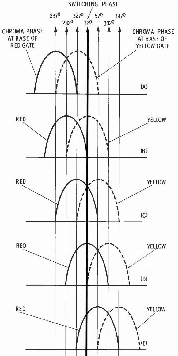
Fig. 4 The amplitude of the chroma sine wave at the base of each gate, during
the time the switching transistor has full conduction, determines the collector
current. Note that the ATC input signal phase is the same as the phase at the
base of the Yellow gate. (A) Input phase is 327°, or greenish-yellow. There
is a fairly large amplitude during the 12° sampling time at the base of the
Yellow gate. This will give partial correction. The signal at the base of the
Red gate is negative, so there will be no collector current. (B) The input
phase is 12° or yellow. Amplitude at the base of the Yellow gate is maximum,
which will give full correction and make skin color orange. There is still
no output from the Red gate since the base signal is zero. (C) Input phase
is 57°, or the desired orange skin color. Partial and equal signal voltages
appear at each base. The resulting small corrections cancel out, leaving the
output still at 57°. (D) Input phase is 102°, or purple. The Yellow gate base
signal is zero; therefore, there is no output. Input to the Red gate is at
maximum and will give full correction to bring the skin color to orange. (E)
Input phase is 147°, or nearly blue. The voltage at the base of the Yellow
gate is negative, so there will be no output. Enough signal appears at the
base of the Red gate to give partial correction and bring the skin color back
to bluish-red.
------------------
The entire circuit is shown in Fig. 3. Both gate transistors are non-conducting until two conditions are fulfilled. The gates are operated in Class "B", and, in the absence of an AC signal (chroma) at the bases, the forward bias is insufficient to allow any significant gain or collector current. Forward bias of just over .6 volt for the bases of both gates is developed across silicon diode DA2. Voltage from this source is temperature compensated, and any increase of base current in the silicon gate transistors resulting from a higher temperature will be reduced by a lower voltage drop across the diode.
In addition, the Red and Yellow gate emitters are returned to ground through the collector-emitter path of QA I, the switch transistor. The gates cannot conduct regardless of base voltage until the switch transistor conducts. A 90° 3.58-MHz signal from the color oscillator transformer is shifted in phase by C774, C780 and L721. The preference control, R132, varies the phase angle 30° on either side of the nominal phase of 12°. This signal is rectified by diode DA 1, and the resultant pulsating DC voltage of positive polarity is applied to the base of QA 1, the switch transistor. The values are chosen so QA I will draw current and be a virtual short circuit only during the very tip of the positive going voltage applied to its base.
During the rest or the cycle it is an open circuit, which disables the gates.
When the switching transistor is conducting and a positive chroma signal is present at the base of QA2, the Yellow gate, the base will be forward biased enough for collector current to flow and the transistor to amplify. The same conditions apply at the Red gate, QA3, except that the chroma signal applied to the base has a 90° leading phase compared to the phase at the yellow gate. Fig. 4 shows the positive-going halves of the chroma sine waves at the bases of the Red and Yellow gates during the time (12°) when the switch transistor is conducting. The output signal from each gate depends upon the instantaneous base voltage at the keying time, and only at this time. The more gate output signal, the more phase correction is possible.
The gated signal at the collector of the Yellow gate is shifted by a 90° lag circuit consisting of LA2 and CA4. Similarly, the output of the Red gate is shifted to 30° (leading) by CA5 and LA3. The signal outputs from both gates are combined and applied to the base of QA4. After phase inversion this signal appears at the collector along with part of the original chroma signal from the input to the emitter.
These two signals are never seen separately on a scope, for they add vectorially to become a sine wave of the resultant phase. From this point the phase-corrected chroma signal goes to the demodulators.
Fig. 5 shows the scope waveforms at the designated test points in the ATC circuit when a gated color-bar generator is used as a signal source.
The output tuning coil, LA5, is tuned by stray capacitance to form a low-Q circuit resonant to about 3.58 MHz. The function of the tuned circuit is to "ring" the clipped correction signal into a more symmetrical waveform.
------------


Fig. 5 Chroma signal waveforms at each stage of the ATC circuit.
(A) The normal keyed-rainbow pulses at the input (test point A), also at the emitter of QA4, the chroma amplifier.
(B) Negative-going pulses at the collector of the Yellow gate (test point B). Maximum correction will be at color bar #1.
(C) Signal at the collector of the Red gate (test point E). Maximum correction will be at color bars 3 and 4.
(D) Negative-going "tails" on all ten bars at the collector of both the Red and Yellow gates is caused by a collector-emitter short in the switching transistor.
(E) Waveform at the base of QA4 (test point G) is the resultant of the output from the Red and Yellow gates.
(F) The signal at the collector of QA4 is the vectorial sum of the input signal (input at emitter) and a 180° inversion of the signal at the base (test point G). The larger amplitude of color bars 1, 2, and 3 is incidental, but it does make all the orange colors brighter.
----------------
Vector diagrams are extremely important in helping us to fully understand the operation of this circuit. Fig. 6 shows the simplified schematic with phase shift components and test-points, and vector diagrams showing the correction of a chroma signal of 30° leading phase (yellow skin hue) and one of 30° lagging phase (red skin hue). here is how it works: With reference to Fig. 6B, the input signal phase is 27°. The Red gate has virtually no signal at its base during switching time (see Fig. 4), so it is non-conducting.
The base of the Yellow gate has the same phase as the input (27°). After inversion in the transistor, the collector (test point B) phase is 207°. The 90° lagging circuit changes the phase to 297° at test points C and G of Fig. 6A. QA4 inverts the phase, so the phase at its collector (test point H) is 117°, which is added to the input phase of 27°, making a resultant signal of 57° for orange skin color. In the vector diagram in Fig. 6C, the 87° chroma signal at the Yellow gate is negative, making this gate inoperative. After the 90° lead change, the signal at the base (test point D) of the Red gate is 357°, and QA3 inverts the phase to 177° at the collector (test point E). The 30° leading network shifts the phase to 147° at test points F and G. After inversion by QA4, the phase at the collector (test point H) is 327°, which added to the input phase of 87° gives a resultant phase of 57° for orange skin color.
In the demodulators, phase differences become amplitude differences.
The scope waveforms shown in Fig. 7 were taken from the picture tube grids, both with no ATC action and with full correction. In general, the pulses representing color bars become nearly identical for the first four bars. This statement is confirmed by color pictures of the color bar pattern on the screen of the picture tube. The large negative-going spike in each waveform is the horizontal blanking spike that comes from the-Y amplifiers whether any color is there or not.
Vector patterns from the scope give the fastest and most accurate visualization of the ATC action, as shown in Fig. 8. With the ATC switch in the FULL correction position, the first three color bars have the same phase (57°), the fourth and tenth bars have some correction, and the other five bars are not affected.


Fig. 6 Simplified schematic and vectorgrams for ATC correction. (A) Simplified
schematic with test points and phase shift components. (B) Vectorgram for ATC
correction of a 30° leading (27°) input chroma phase. (C) Vectorgram for ATC
correction of a 30° lagging (87°) input chroma phase.

Fig. 7 Picture tube grid waveforms produced by a gated-rainbow pattern.
(A) Normal bar pattern at the red grid of the picture tube. (B) Red grid with FULL ATC correction. (C) Normal bar pattern at the blue grid of the picture tube. (D) Blue grid with FULL ATC correction. (E) Normal bar pattern at the green grid of the picture tube. (F) Green grid with FULL ATC correction.
------------
TABLE 1

DC voltage chart of the ACC circuit. The high chroma IF bias at 0% is due to color killer action. The last three lines are the chroma IB tube voltages without the additional bias from QA5.
ACC VOLTAGES
----------------
Magnavox ACC
Another feature of the T940 Magnavox chassis is the ACC circuit which has a double action. As shown in the simplified schematic of Fig. 9, a total of four DC voltages are applied to the grid return of the chroma IF tube: 1) Negative voltage from the plate of the color killer is applied when the burst level is too low or missing. 2) Negative voltage from a killer detector diode is obtained through the 8.2-meg resistor. This voltage varies according to the amplitude of the burst signal. 3) A positive voltage applied through the 1.5-meg resistor from its own cathode cancels some of the negative voltage from the killer detector to cause more of the change in control voltage (from the burst) to reach the grid. 4) In addition to these conventional voltages, a variable positive voltage comes from QA5, the ACC transistor. Chroma voltage from the top of the color control is rectified by diode DA4, filtered by CA 13 and applied to the base of QA5. The more positive the base voltage, the less positive the collector voltage, which is applied through a 1.5-meg resistor to the grid return of the chroma IF tube.
This voltage also cancels out part of the negative voltage obtained from the killer detector, and since it is variable, makes the ACC voltage at the chroma IF tube more negative when the color is stronger.
The DC voltage chart in Table 1 gives the important voltages in the ACC circuit. ACC voltages were obtained by comparing the chroma IF grid and cathode voltages measured to ground; this is the easiest way during troubleshooting. Slightly better accuracy can be obtained by measuring directly from cathode to the .047-mfd capacitor in the grid circuit. The difference in the voltage reading of the chroma IF ACC bias and the same reading with the base of QA5 grounded represents the added ACC gain correction obtained from the QA5 circuit. This extra control is very noticeable above chroma level of 75%. You might think that obtaining part of the ACC from the amplitude of the chroma signal, rather than the burst amplitude alone, would defeat the natural color saturation in scenes having bright colors or others with little color. While there is some of this effect, it is overshadowed by the minimizing of another common problem: The many times a station will broadcast extremely strong or abnormally weak color without any corresponding change in the burst.
Troubleshooting the ATC Circuit
The first step in analyzing any ATC malfunction is to try the normal sequence of customer adjustments. Slide the ATC switch (on the front panel) to the OFF position, and with a color picture tuned in, adjust the tint control for normal skin color. If it is impossible to obtain good skin color, the ATC circuit is not at fault. If the picture has normal tint and saturation, QA4, the chroma amplifier on the ATC board is working and the circuit has B+ voltage. Weak or missing color can be caused by the color IF, video IF's, killer detector, 3.58 MHz oscillator, etc., the same as in any color TV. Connect a jumper wire from the top of the color control to the demodulator grid, pin 7; if the color improves, the ATC circuitry is at fault.
Slide the ATC switch to the FULL correction position. The preference control (with other controls on the back near the top) should change skin hues from greenish-yellow to magenta. If only magenta skin hues are seen, the Red gate may be defective; conversely, if the skin colors are greenish-yellow, the Yellow gate may not be working.
Defects in the gate circuits are best checked in the shop using voltage and waveform analysis to find the defective component. Use a gated-rainbow bar pattern and check for scope waveforms similar to those in Fig. 5.
Loss of the 3.58-MHz switching signal or an open or shorted QA1 switching transistor will eliminate any change in the color hues as the preference control is adjusted through its range. An open switch transistor will eliminate all gate action, and there will be no change in the color when either the preference or the ATC switch is adjusted. A shorted switch transistor will allow both gates to conduct at all times; the preference control will have no effect, but switching the ATC on FULL will brighten all ten color bars. A loss of 3.58-MHz signal to the switching transistor will give the same symptoms as an open transistor.
Conclusion
The Magnavox ATC circuit actually functions precisely as explained here. The action is strictly by phase changes (with a minor amplitude side-effect) and, therefore, is instantaneous in action without time lag, locking or registration effects. There are no adjustments to be made on the board, so it is not necessary to "tune-up" anything. When you are accustomed to the sight of one (never more than two) completely red bar on a gated rainbow color display, it gives one a peculiar feeling to see four (sometimes nearly five) reddish-orange bars on the screen. Obviously, it is four times less critical of skin color than an uncorrected signal.
One small drawback is inherent in this type of phase correction: red becomes orange and greenish-yellow becomes orange regardless of whether these hues are applied to a face or some other object in the picture. This is the reason for the FULL and PARTIAL positions on the ATC switch. Usually the PARTIAL correction would be used where the variation in skin color is not too extreme. Any change in areas of the picture other than skin hues would be minimized.
All factors considered, this ATC circuit is a fascinating addition to modern color TV engineering.


Fig. 8 Vector waveforms of color bars.
(A) Normal vector pattern with the third "petal" at 90°.
(B) ATC switch in PARTIAL position pulls the first and third petals nearer to bar two.
(C) With the ATC switch in the FULL position, the first three petals are all at 57° (orange).
(D) FULL correction with the preference control adjusted for yellow faces.
(E) FULL correction with the preference control adjusted for magenta faces.

Fig. 9 Simplified schematic of the T940 ACC circuit. ACC is proportional to
both burst level and chroma amplitude.
RCA's Accu-Tint
The RCA Accu-Tint (A-T) system produces three basic changes when the A-T switch is turned to ON: The phase of the 3.58-MHz color subcarrier applied to the B-Y chroma demodulator circuit is changed so that it is nearer the phase of the subcarrier supplied to the R-Y demodulator.
The output of the B-Y demodulator circuit is reduced about 33 percent.
The screen color is changed from the normal blue-white to a brown-white, or sepia. (This "warming" of the screen color "temper attire" occurs only when a colorcast is received (killer inoperative) and the A-T switch is ON.) The result of these A-T actions is to increase the level of red and decrease the level of blue and green in the color picture.
Fig. 10 shows the demodulator and-Y amplifier circuits of the new RCA CTC39X chassis, which is similar to the CTC38X except for minor changes in the video amplifiers, and the addition of the A-T circuit.
B-Y Phase Change
The 3.58-MHz subcarrier for the R-Y demodulator is taken directly from the secondary of T703, while the phase of the 3.58-MHz carrier for the B-Y demodulator is made "leading" by a high-pass filter.
When the A-T switch, 5106, is in the OFF position, this high-pass filter consists of C732, L703 and R735. With this arrangement, the normal (A-T off) B-Y phase leads the R-Y phase by about 105 degrees.
When the A-T switch is turned to ON, L712 and R797 are added in series with L7O3 and R735. This reduces the lead of the B-Y phase to 90 degrees or less (RCA has not announced the exact figures). R-Y carrier phase is changed slightly by the difference in loading on the secondary of T7O3, but most of the shift is in the phase of the B-Y chroma subcarrier.

Fig. 10 Complete schematic of the demodulators and color-difference amplifiers
in the new RCA CTC39X chassis. Notice especially the circuits connected to
switch S106, the Accu-Tint OFF/ON switch.
B-Y Amplitude At The CRT Blue Grid
Skin coloring that is acceptable to many people can be obtained with only an R-Y color signal, so logically the next step is to reduce the amount of blue and green in the color picture.
The second section of S106 performs a double function. One of these, when the A-T is ON, is to ground R795. This decreases the output of the B-Y demodulator so that the signal at the CRT blue grid is reduced from the normal 120 percent of red to about 80 percent of red.
R-Y amplitude is unchanged, but because G-Y is made from R-Y plus B-Y, it also will be reduced.
Change in CRT Screen Temperature
When the A-T is ON, the junction of R793, R794 and R178 no longer is grounded through terminal 4 of S106. The negative-going horizontal pulse originating at the center lug of the kine bias control is reduced by a voltage divider consisting of R793, R178 and R795, and then is applied through the .047-mfd coupling capacitor to the grid of V704B, the B-Y amplifier. After amplification and phase reversal (180 degrees) by the tube, it becomes a small, positive-going pulse at the plate, which is fed through the .01-mfd capacitor to the anode of diode CR707 and the blue grid of the CRT. On the cathode of CR707, a large negative-going pulse from the kine bias control is applied to the cathode of CR707 and turns it on, resetting the charge on the .01-mfd capacitor every cycle, and thus maintaining the CRT grid DC voltage constant regardless of the chroma waveform.
The positive-going pulse at the anode of CR707 and the negative going pulse at the cathode add together to produce a larger pulse.
Because the DC voltage on the CRT grid is "clamped" to the negative tip of the pulse, the DC voltage on the CRT control grid is made less positive (compared to the CRT cathode), and the current of the CRT blue gun is reduced.
A small pulse also is applied through R793 and R794 to the cathode of V705, the R-Y amplifier.
Since the signal is applied to the cathode, this pulse is amplified without phase inversion, and the negative-going pulse of a few volts appears at the anode of diode CR705.
A large negative-going pulse from the kine bias control is present at the cathode of CR705. The true voltage across the diode is the difference between the pulse voltage on the anode and the pulse voltage on the cathode. The effect is the same as a decrease in the pulse from the kine bias control, and causes the red grid of the CRT to become more positive by a few volts, increasing the red gun current.
During normal operation, small samples from the plates of both the R-Y and B-Y amplifiers are matrixed to produce a-(G-Y) signal at the grid of the G-Y amplifier.
Because of phase inversion across the tube, a G-Y signal is developed at the plate and applied to the 'green grid of the CRT. Voltages in the G-Y stage are not affected by the addition of the extra A-T pulse voltages at the R-Y and B-Y amplifier plates; because the polarity of one is positive-going and the other is negative-going and the amplitudes of the two signals are nearly equal, they cancel at the G-Y amplifier grid.
This method of using pulses to brighten the red, dim the blue, and leave green unchanged has another beneficial effect: When the color killer operates during b-w programs, the R-Y and B-Y amplifiers are biased to cutoff. Because of this, the A-T pulses cannot be amplified and, therefore, do not appear at the plates of the tubes or the anodes of the DC restorer diodes. Thus, the screen color is a normal blue-white, not sepia. (Of course, if the station leaves their color carrier on during a b-w commercial, or if the color killer malfunctions and does not operate normally during h-w programs, the screen color will be sepia if the A-T switch is in the ON position.) Turning off the Accu-Tint circuit restores the B-Y demodulator phasing and amplitude, and restores the screen color to normal.
Conclusion
This RCA circuit prevents unwanted changes in skin coloration when the receiver is switched from channel to channel and/or when programming changes. Changes to the previous circuit are not extensive, and no critical or trouble-prone components have been used. Consequently, the circuit should be relatively service-free.
However, we must recognize that, despite excellent engineering and modern components, each basic type of automatic tint modifier is a stopgap emergency measure made desirable only by the continuing delay of the broadcasting industry in standardizing color hue. Also, it should be remembered that the circuits which most effectively eliminate green or purple faces also produce the most distortion of colors (except orange).