For many years, two main advantages of the digital processing of analog signals have been known. First, if the transmission system is properly specified and dimensioned, transmission quality is independent of the transmission channel or medium. This means that, in theory, factors which affect the transmission quality (noise, non-linearity, etc.) can be made arbitrarily low by proper dimensioning of the system.
Second, copies made from an original recording in the digital domain are identical to that original; in other words, a virtually unlimited number of copies, which all have the same basic quality as the original, can be made. This is a feature totally unavailable with analog recording.
A basic block diagram of a digital signal processing system is shown in FIG. 1.
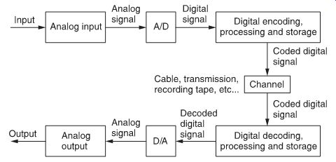
FIG. 1 Basic digital signal processing system.
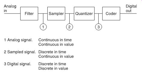
FIG. 2 An analog-to digital conversion system.
Digital audio processing does require an added circuit complexity and a larger bandwidth than analog audio processing systems, but these are minor disadvantages when the extra quality is considered.
Perhaps the most critical stages in digital audio processing are the conversions from analog to digital signals, and vice versa.
Although the principles of A/D and D/A conversion may seem relatively simple, in fact they are technically speaking very difficult and may cause severe degradation of the original signal.
Consequently, these stages often generate a limiting factor that determines the overall system performance.
Conversion from analog to digital signals is done in several steps:
• filtering--this limits the analog signal bandwidth, for reasons outlined below
• sampling--converts a continuous-time signal into a discrete time signal
• quantization--converts a continuous-value signal into a discrete-value signal
• coding--defines the code of the digital signal according to the application that follows.
FIG. 2 shows a block diagram of an analog-to-digital conversion system.
Prev. | Next