Linear (or uniform) quantization
In all the examples seen so far, the quantization intervals Q were identical. Such quantization systems are commonly termed linear or uniform. Regarding simplicity and quality, linear systems are certainly best. However, linear systems are rather costly in terms of required bandwidth and conversion accuracy. Indeed, a 16-bit audio channel with a sampling frequency of 44.056 kHz gives a bit stream of at least 16 × 44.056 = 705 × 10^3 bit s^-1 , which requires a bandwidth of 350 kHz--17.5 times the bandwidth of the original signal. In practice, a wider bandwidth than this is required because more bits are needed for synchronization, error correction and other purposes.

FIG. 1 Non-linear quantization.
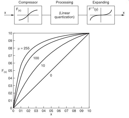
FIG. 2 Characteristics of µ-law compressors.
Since the beginning of PCM telephony, ways to reduce the band widths that digitized audio signals require have been developed. Most of these techniques can also be used for digital audio.
Companding systems If, in a quantizer, the quantization intervals Q are not identical, we talk about non-linear quantization. It is, for instance, perfectly possible to change the quantization intervals according to the level of the input signal. In general, in such systems, small-level signals will be quantized with more closely spaced intervals, while larger signals can be quantized with bigger quantization intervals.
This is possible because the larger signals more or less mask the unavoidably higher noise levels of the coarser quantization.
Such a non-linear quantization system can be thought to consist of a linear system, to which a compander has been added. In such a system, the input signal is first compressed, following some non-linear law F(x), then linearly quantized, processed and then, after reconversion, expanded by the reverse non-linearity F-1 (y) (see FIG. 1). The overall effect is analogous tocom panders used in the analog field (e.g., Dolby, dBx and others).
The non-linear laws which compressors follow can be shown in graphical forms as curves. One compressor curve used extensively in digital telephony in North America for the digitization of speech is the 'µ-law' curve. This curve is characterized by the formula:
Curves for this equation are shown in FIG. 2 for several values of µ. In Europe, the 'A-law' curve is more generally used (FIG. 3).
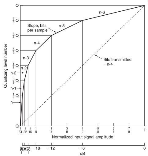
FIG. 3 A-law characteristic curve.
The (dual) formula for the 'A law' is:
F(x) = Ax/1 + log A for 0 < x <V/a
F(x) = V + V log (Ax/V)/1 + log A for V/a < x < V
In practice, it is important that the non-linearities at the input and the output of any audio system are very closely matched.
This is difficult to achieve with analog techniques, so compressors are usually built in to the conversion process.
The big advantage of these companded systems is that the signal-to-noise ratio becomes less dependent on the level of the input signal; the disadvantage, however, is that the noise level follows the level of the signal, which may lead to audible noise modulation.
Floating-point conversion
A special case of non-linear quantization, used in professional audio systems, is the 'floating-point converter' (FIG. 4).

FIG. 4 Floating-point converter principle.

FIG. 5 Signal-to-noise ratio of a floating-point converter.

FIG. 6 A block floating point converter.
Sampled signal is sent through several selectable paths, each with a different gain, depending on the input level of the signal. Path, and hence gain, is selected by a logic monitor circuit in order to make maximum use of the linear A/D converter without over loading it. The output from the A/D converter, called the 'mantissa' in an analogy with logarithmic annotation, is meaningless without a way to indicate the gain that was originally selected.
This information is provided by a logic output from the monitor circuit, called the 'exponent'. The exponent and mantissa, taken together, give an unambiguous digital word that can be reconverted to the original signal by selecting the corresponding (inverse) gains in the decoding stage. In this way, 2 bits of exponent can indicate four different gains. If we select these gains as 0, 6, 12 and 18 dB for instance, the two additional bits provide an increase of 18 dB over the dynamic range of the basic system.
Because the signal level determines basic system gain, noise modulation is unavoidable. This may become audible, for instance, with a high-level, low-frequency signal: in this case, noise modulation will not be masked by the signal.
Due to the effects of noise modulation, a distinction must be made between the dynamic range and the signal-to-noise ratio.
The dynamic range can be defined as:
...whereas the signal-to-noise ratio is:
A curve for the signal-to-noise ratio of a typical floating-point converter with a 10-bit mantissa, a 3-bit exponent and 6-dB gain steps is shown in FIG. 5. Although, theoretically, this system maximum signal level (RMS)
RMS level of quantization noise signal without signal level (RMS)
RMS level of quantization noise signal with provides the same dynamic range as a 17-bit linear system (i.e., over 100 dB), the signal-to-noise ratio is unacceptable for high quality purposes.
In spite of this, high-quality floating-point converters having, say, a 13-bit mantissa and 3-bit exponent are still considered for digital audio purposes, as they are considerably cheaper than linear systems.
Block floating-point conversion
When a low bandwidth is of utmost importance, block conversion can be used. This technique is also known as near-instantaneous companding (in contrast to basic floating-point or other companding systems). The term 'near-instantaneous' is used to describe the fact that not every sample is scaled by an exponent, but a number of successive samples (usually 32). Each block of samples is then followed by a scale factor word, so that, at the receiving end, each block can be correctly scaled up again (FIG. 6).
This system is rather expensive as far as hardware is concerned, but permits significant reductions in bit rates. Consequently, a typical application is digital transmission of audio signals in radio networks.
Subjective listening tests have shown that an original 14-bit system compressed to 10 bits is almost indistinguishable from a 13 bit linear system, although the signal-to-noise ratio limitations of a floating-point converter remain valid.
An example of such a system is the BBC's NICAM-3 (near-instantaneous companding audio multiplex), which permits transmission of six audio channels over one (standard) telephony 2048 kbit s^-1 circuit.
Differential PCM and delta modulation

FIG. 7 One-bit A/D converter.

FIG. 8 Block diagram of 1-bit A/D converter.
Instead of transmitting the exact binary value of each sample, it is possible to transmit only the difference between the current sample and the previous one. As this difference is generally small, a smaller number of bits can be used with no apparent degradation in performance. Operation is fairly straightforward: one sample is stored for the complete sample period, then added to the received difference signal to obtain the next sample. This sample is then stored until the next received difference signal.
Differential PCM, in fact, is a special type of predictive encoding. In such encoding schemes, a prediction is generated for the current sample, based upon past data; the correcting signal is simply the difference between the prediction and the actual signal.
As sampling rate increases, the differences between previous and present samples become smaller, so that, in the extreme for very high sampling rates, only 1 bit is needed for the error signal to indicate the sign of the error; in this case we talk about delta modulation.
FIG. 7 shows a basic single-bit A/D converter. The input signal is compared with the output of a 1-bit D/A converter; the resulting voltage is then compared with a reference and the output used to increment or decrement the DAC value. For any input signal the system needs to perform a certain number of iterations to obtain the required resolution. Each iteration results in a high or low signal at the output of the A/D converter. Looking at the output we see a pulse train whose mean value equals the level of the input signal. The analog input has been converted to a binary bit stream. The typical sampling frequency in 1-bit converters is several megahertz.
Because the serial bit stream is of little practical use, it is mostly converted to a multi-bit format (e.g., 16-bit) with a much lower sampling rate. This is done in a digital filter, a so-called decimation filter, which includes noise shaping (FIG. 8).
In a further step, the transmitted data can be used to indicate not only the sign of the error, but also the step size. For example, a continuous series of ones means that the signal is quickly increasing, so the step size can be increased; if ones and zeros are alternating, step size can be reduced. Such strategies are called adaptive differential PCM (the quantization interval is changed) or adaptive delta modulation (the step size is changed). Although these techniques have some interesting theoretical and practical properties, it is presently difficult to use them for high-quality applications.

FIG. 9 SBM effect.
Super bit mapping (SBM)
SBM is an enhanced A/D conversion technique used for disc mastering and also on some recent DAT recorders (as from 1994).
When the CD technology started, the amount of 16 bits per sample was specified. At that time 16 bits seemed ambitious, as the available technology only allowed about 14-15 bits.
Now, however, it is no problem to convert substantially more than 16 bits per sample, and A/D conversion in professional sound studios is performed at 18 or 20 bits, if not higher. Of course, if a conversion is made at 18 or 20 bits and the disc specification allows 'only' 16 bits, there is a need for reduction. SBM uses the extra bits to increase the accuracy of the 16-bit signal.
A very important point to note is that the use of such techniques poses no compatibility problems at all. A disc to which the SBM principle has been applied can be played back without any problem in any CD player. If a digital recording was made using a 20-bit A/D converter, the last 4 bits (bits 16-19) cannot be implemented in the 16-bit data stream on the disc, but these bits can be used to increase the accuracy of the least significant bits of the 16-bit samples and thereby maintain compatibility, decrease the noise level and increase the sound quality. FIG. 9 illustrates the SBM effect.
SBM operation is highly complex and involves higher order mathematics, which is beyond the scope of this publication. It should always be remembered, however, that these calculations are applied to digital audio data not to analog signals. FIG. 10 presents an SBM block diagram.
The input is audio data (more than 16 bits per sample), each channel is calculated separately, but it is obvious that in order to maintain sound integrity, the calculations performed on one channel must have at some points input from the other channel.
Audio data will be calculated by blocks of 512 samples (512 samples at a sampling rate of 44.1 kHz equals a sound block of 11.6 ms). Any DC component will be subtracted from the input.
The next block is the simultaneous masking curve calculation.
The input blocks (512 samples left and right channel) are processed by Fast Fourier Transforms in order to analyze the input audio. This calculation determines the signal power in each frequency band, the total audio frequency spectrum being split into a number of well-defined sub-spectra. Note that this is a known psychoacoustic fact: the human ear works according to similar principles, analyzing signal power at predetermined sub divisions of the total audio spectrum.

FIG. 10 SBM block diagram.

FIG. 11 SBM noise shaping.
At this point, and also in the next block, the equi-loudness masking block, the SBM system determines whether one part of the incoming signal can mask another part and where and at what level quantization noise is found.
The knowledge gained in previous blocks will be used to calculate filter coefficients which will be used to perform noise shaping. Noise shaping (see also Figure 11) is a technology able to eliminate quantization noise contents from the audible spectrum.
In the next stage, noise shaping is performed based upon all the previously performed calculations. FIG. 11 illustrates the SBM noise shaping.
In comparison with noise shaping filters used at the D/A side of CD players, it should be noted that in this case the filter coefficients are adapted continuously, so the operation is far more complex and needs a very high calculation speed.
The result of SBM is a 16-bit signal with a lower quantization noise, a higher linearity and therefore a better sound definition.
Direct stream digital (DSD) The latest approach to digital recording for the next generation of optical disc readers is DSD. Compared to the conventional CD, which makes use of linear PCM, DSD offers the possibility to encode and reproduce extreme high-quality sounds. The basic concept of the DSD format is a 1-bit A/D-D/A conversion system operating at a very high frequency of 2.8224 MHz. The basic principles of 1-bit A/D-D/A conversion have already been explained in this section; the state of technology and design of circuitry have now allowed these principles to be put into practice up to a rather extreme level. Together with the more powerful and faster operating microprocessors, which allow more complex mathematics, the DSD format is capable of reproducing sounds beyond 100 kHz.

FIG. 12 DSD block diagram.

FIG. 13 Multi-bit PCM.
In spite of the progress of multi-bit PCM and even if bit rates used in recording studios have been raised to 24 bits, one major disadvantage will always be present: filtering. As seen in Section 2, the maximum frequency that can be recorded is half the sampling frequency. In the case of the CD format with a sampling frequency of 44.1 kHz (f s ), steep 'Brick Wall' filters have to be used to filter out 22.05 kHz but leaving 20 kHz. This format is not only limited in frequency, but also the influence that these filters have on the lower part of the audible range was seen as a system constraint.
Professional analog tape recorders used in studios are able to record signals up to 50 kHz, including the higher harmonic frequencies produced by musical instruments. These harmonic frequencies have their influence on the original music. To archive these recordings with the important high-frequency information, a new higher performing A/D conversion system had to be developed. The logical answer to these constraints of conventional CD processing, and the need to incorporate the advantages of analog recording, was indeed DSD.
DSD is in theory a 'simple' 1-bit conversion system operating at a sample frequency of 2.8224 MHz (64 × f s ). A simple block diagram of the DSD process is shown in FIG. 12. When CD systems were originally designed, the theoretical basis for 1-bit high-frequency sampling was of course already available; at that time, however, it was not yet technologically possible to produce such high-speed A/D converters. The exponential speed of technological progress has now made it possible to produce the technology needed at an affordable price.
After 1-bit sampling at 64 f s (2.8224 MHz), the signal is encoded and formatted similar to a CD; at this point, there is also some extended encoding and encryption which will be explained in subsequent sections, but the basic ideas as used in CD have been retained. The most interesting part of DSD is that, after read-out of a disc, and after decoding/decrypting, the signal stream is such that it can be presented virtually directly to an amplifier and speakers. The main reason is again the use of a 1-bit signal at a very high frequency, which might even be compared to the signal coming from the needle of a pick-up, the only difference being the low-pass filter.
One of the reasons mentioned to quit the conventional multi bit PCM system was the need for complex decimation and interpolation.

FIG. 14 One-bit delta-Sigma modulator.
As can be seen in the most simple presentation in FIG. 13, multi-bit PCM requires more steps to convert the analog input signal into the digital format. Also, to convert the digital signal read out by the laser to the original analog signal, complex circuitry is required. More circuitry needed for conversion results in a decreased quality of the sound.
The main differences between conventional CD processing and DSD processing are:
• 16-bit sampling versus 1-bit sampling;
• 44.1 kHz sampling rate versus 2.8224 MHz sampling rate;
• bandwidth limited to just above audible range versus band width well beyond audible range;
• the need for noise shaping, digital filters, interpolation versus much reduced need for such circuitry;
• the need for high-precision D/A converter circuitry versus the possibility to even replace D/A circuitry by simple low pass filtering.
One possible negative factor for DSD is the amount of data space needed for this higher bit rate: where a conventional CD requires around 650 Mbytes for a 74-minute disc, the DSD equivalent needs roughly five to six times more (around 3.5 Gbytes). The use of new and improved laser and disc techniques (see also Section 18 on SACD) has made this possible.
The main part of the DSD encoder is the Delta-Sigma (Delta-S) modulator. FIG. 14 shows the simple block diagram of the Delta-S modulator.
The theory of this 1-bit Delta-S modulator has already been described previously; the basic design is unchanged.
The output of D switches between +1 and -1 when the input is 1 or 0, respectively. Suppose we have a situation with 0 V at the analog input and the output of Q was zero before. At the time of sampling, the output of D becomes -1 V. Connected to the inverting input of ?, the output of ? will become 1 V. Passing this 1 V through S will change the output of Q to 1. At the next sample, the 1 is returned to ?, resulting in -1 V at its output. This -1 V is added to the previous value of S, giving a 0 at its output, making the output of Q return to 0. In this stage the converter is back to its start position.
Consequently, the output of the DSD converter will alter between 0 and 1 when 0 V is applied at the input.
When the input level is at maximum, suppose this is 1 V; at this time the output of ? is 2 V (suppose there was 0 V at the previous sample on the output of Q so there was -1 V at the output of D). This 2 V is added to the previous output of S. If it was 0 V in the previous sample, the output will become 2 V. Q will then output a '1'. This '1' is returned to the inverting input of ?, resulting in a '0' on its output. This '0' will not change the output of S, so at this moment the modulator is in a stable situation with '1' always at the output.
A similar explanation can be made when applying the minimum level or changing signals at the input.
FIG. 15 shows the output signal from the Delta-S modulator in the case where a sine wave is on the input. In the case of the positive-going waveform the density of the ones is much higher than in case of the negative-going waveform. In fact, if the input signal is at the maximum level the digital output stream will be all '1' and if the input signal is at minimum level it will be all '0'.
As a logical conclusion to the name Direct Stream Digital, the analog signal is directly converted to a pulse train of zeros and ones. To convert this continuous bit stream back to an analog signal, in order to feed it into an amplifier and/or speakers, there is no real need for a dedicated D/A converter, although the decision to use one or not can still be taken on grounds of specific needs or designs. A low-pass filter can be used instead of the D/A converter.

FIG. 15 DSD converted signal.
The use of a low-pass filter for this purpose can be explained in a simplified--but valid--way: a low-pass filter is an integrator function, and an integrator function is a way to calculate the surface. If we now refer back to the previous illustration, it can be seen that the sine wave is the integrated function of the under lying rectangular patterns as caused by the '1' and '0' bits, keeping in mind that the '0' bits should be considered as '-1' to create the negative part of the sine wave. The greater the concentration of logic ones, the higher the sine wave rises; the greater the concentration of logic zeros, the lower it falls. In other words, by integrating the output bit pattern we are effectively recreating the corresponding audio spectrum.
Additionally, because of the high sampling frequency of 2.8224 MHz, DSD has the noise level shifted to higher frequencies (remember that one of the original purposes of the 1-bit over sampling technique was noise shaping). This is contrary to the linear PCM without noise shaping, where the noise has a constant level depending on the bit resolution. These frequencies are in the inaudible part of the spectrum and can be filtered out. Such circuitry does need some attention to the analog parts; these need to be of good quality, but these days it should not be a problem.