We've all heard the joke about a person with so many fillings that he heard voices in his head whenever he passed within five miles of a transmitter. I won't vouch for its veracity, but there is little doubt that radio-frequency interference (RFI) is becoming ever more prevalent as spectrum crowding increases. In this installment of Audio Corner we'll talk about RFI that affects audio equipment. I'll also refer to it as HFI, short for hi-fi interference. The source of HFI is not only radio transmissions, but also the myriad noises spraying out of microprocessor-equipped appliances. As you know, the prevalence of square waves in computer circuitry yields a rich harvest of harmonics, many of which can interfere with TV and audio products.
How HFI works
Audio Rectification
You might be wondering how a radio frequency signal of several megahertz is able to affect an audio circuit, given the great difference in frequency. Well, of course, the problem stems from something we're all familiar with, diode rectification. Every transistor and IC has diode junctions. Given RF of sufficient amplitude, they will rectify the signal, stripping off the carrier, leaving only the modulation, which is generally in the audio passband. This occurs with FM as well as AM transmissions, thanks to a phenomenon called slope detection. Actually, there are many other potential detectors besides semiconductors in side any piece of electronic gear.
Wherever two dissimilar metals join together, a diode junction is possible. This is not nearly as much of a problem when one of the contacts is gold. Thus you notice that high end audio gear often uses gold plated phono jacks.
Another potential trouble spot occurs between the circuit board land and chassis on equipment that eschews wired grounds in favor of compression connections. The manufacturer is hoping that the board will be screwed down tight enough to make proper contact. This is an excellent way to ensure that the unit will have strange ground-failure related problems after several years of moderate use.
Other Effects
Some audio circuitry is sufficiently linear at a given radio frequency that rectification does not occur. The offending signal may pass right through several stages of amplification and on to the output amplifiers, which attempt to reproduce the inaudible RF at the cost of audio distortion.
This is a tricky one to locate, but a scope should do it. Another possibility is that de from detected FM interference may un-bias a stage, causing troubles ranging from distortion to repetitive failure of a semiconductor. Fortunately, this sort of trouble is uncommon.
Entrance Points
Interference can enter a system along one of three paths. First, it simply can penetrate the cabinet. Secondly, it can use the power line. Finally, interconnecting cables offer another entry point. When trying to eliminate HFI, we first must discover which path it uses, then apply appropriate reduction techniques.
During diagnosis, we need to ask some questions.
Does the interference occur on all programs, or just one particular one, such as phono? Does the unit have to be turned on to have a problem? (Don't laugh. I've worked on televisions that only picked up CB interference when they were powered down.) Is the interference from a commercial radio or TV station, or is it from one of the personal communications bands? Is it even modulated with intelligence, or just some stray garbage from a microprocessor clock, aquarium heater, or the like? If you suspect the noise enters from the power line, try disconnecting the ac cord while monitoring the output. If the noise immediately disappears, you've found the en trance way. If it dies off slowly as the filter capacitors discharge, it's coming in another way. On amps and receivers that have a speaker protection relay, you may need to jump the contacts out of circuit to make this test. You might also get a big pop out of the speakers if the plus and minus supplies discharge at different rates.
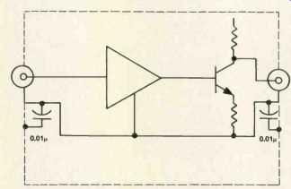
Figure 1. Capacitors bypass shield to chassis, keeping RFI out of amplifier
ground.
HFI is insidious. The mere fact that input cables are properly shielded and grounded does not preclude the possibility that they will act as antennas at some frequency.
For example, see Figure 1, which shows a hypothetical amplifier stage. Even though the shield is grounded, it still can couple noise into the cabinet from outside. This hap pens because an audio ground is not necessarily an RF ground. The wire connecting the input jack shield to circuit ground may be a dead short at 20kHz, but an inductor at RF. In that instance, noise will be coupled into the ground system of the amp.
Countermeasures
There are many ways of reducing HFI. The best is to keep it out of the system altogether. Second, and more realistic, is to design the circuitry to be as immune as possible In practice, we must use a 2-pronged attack, reducing both infiltration and susceptibility to a minimum.
Going back to our previous example, entry via interconnect cables, let's trap out the noise at the input jack. One way is to connect a capacitor between the input jack ground and chassis ground. A 0.01mF ceramic usually works. Keep the capacitor leads as short as possible and solder them in place. Now we've provided a low impedance path to the chassis for any RF that might show up on the shield.
Noise entering via the power line can be reduced by adding a couple of chokes and capacitors. See Figure 2. You can't assume that just because a piece of equipment is expensive, and was manufactured by a major electronics company, it has proper line filtering. As a matter of fact, it probably doesn't. Quite often, the power transformer offers the only protection from RFI. Noise filters that plug in on the receptacle end are not always effective, especially if the ac cord itself is acting like an antenna. One thing you can try that does not require internal modifications is to wrap several turns of the line cord around a ferrite core such as is found in most AM radios. A piece of tape serves to secure it in place. This works most effectively in the AM (MW) frequency band.
Internal noise, generated by clocks, oscillators and digital switching circuits, should be eliminated during the de sign phase by proper attention to bypassing logic ICs and providing separate ground returns for audio and digital signals. If you have trouble with a unit, it may be necessary to add 0.1mF bypass capacitors between Vcc and ground at as many logic ICs as is practical. You might also experiment with grounding, but this is often difficult, especially when the manufacturer has not done his homework.
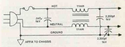
Figure 2. RFI line filter, good for 1 - 100MHz
A column of this length can no more than touch briefly on the subject of RFI. For your further study, I'd recommend The Radio Amateur's Handbook, published by the American Radio Relay League, Newtington, CT 06111; and Consumer Electronics Systems Technician Interference Handbook-Audio Rectification, published by the Consumer Electronics Group of the EIA, 2001 Eye St. NW, Washington, DC, 20006.