By Martin Middlewood [Mr. Middlewood is an electronics engineer with the Service Instruments Division of Tektronix, Inc.]
Video cassette recorders have been with us for several years now and their popularity is growing daily by leaps and bounds. This article concentrates primarily on the operation of the servo mechanisms found in both the VHS and Beta formats, traditionally among the most troublesome of all VCR operating systems.
The VCR, like the audio recorder, is a magnetic recording system. There are several differences in the two systems, however. VCR's record a wider and higher frequency spectrum (30 Hz to 4 MHz). To do this, they use a narrower head gap and a 2-headed helical scan method of recording. Audio recorders record material longitudinally along the length of the tape; VCR's record material obliquely across the tape. Each head has a different azimuth to eliminate luminance crosstalk between adjacent tracks. Because each head must play back only the tracks it has recorded, a control system is necessary. The control head writes a control pulse on the control track each time one of the heads records its track. This pulse references the servo system to that track, and if the heads aren't reading the proper tracks, the servo system adjusts the speed of the head drum until they are.
Chrominance interference between the recorded tracks is eliminated by formatting signals on the tape to cancel out chrominance crosstalk. The two most popular systems for doing this are the VHS system, which rotates the chroma phase 90° from line to line, and the Beta system, which inverts chroma phase every other horizontal line that the A -head records.
There are two ways of looking at a VCR. Disregard the difference in format between VHS and Beta machines, and you'll find the same information on the tape: audio signals, control pulses, (black and white) and chroma (color) signals. Except for the control pulses, these are the same signals that you find in any color television. From the serviceman's point of view, both ways of looking at a VCR are equally valid. In order to service VCR's, you need to know this information is recorded on the video tape, and how it's processed for recording on the video tapes, and how it's processed for reproduction, or playback, on the television monitor. To understand these things, let's break the VCR down into its essential blocks and look at the operation of each block. The first two blocks, the power supply and audio blocks, should be fairly familiar to you.
Therefore, this article's discussion of them is limited and more time is spent on one of the less familiar blocks-the servo section. The other two essential blocks are the luminance and chroma sections. They will be covered in another article.
In reality, the VCR has more blocks than this, as any VCR service manual indicates. In the manual, you're likely to find timing, memory, loading-unloading, and tape transport blocks. The five basic blocks covered here should, however, put you well on your way to understanding VCR's.
Whenever you're looking at a VCR, remember that you're looking at integrated circuits. This means that some of the portions of the blocks discussed here may be inside an IC. But with a little help from the service manuals of the VCR's you're dealing with, you should overcome this.
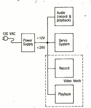
Fig
1 The VCR Power supply transformer steps down the incoming voltage. Secondary
windings feed regulated DC power supply circuits
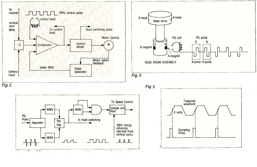
Fig 2 The VCR has three external recording inputs. Depending on the input,
one of the incoming signals is compared to the pulse generator (PG) pulse.
Differences between the input signals and pulse generator pulse results
in a change in voltage at the output of the comparator which adjusts the
motor speed.
Fig 3 Magnets in the head drum assembly induce a signal in the pulse generator coil as they pass. The A-magnet passes the PG coil just as the A-head begins to cross the tape. The output is used to control head switching and the speed of the head drum motor.
Fig 4 The PG pulse is used to control the speed of the head motor and head switching.
Fig 5 When the speed and phase are correct, the trapezoid and sampling pulse line up as illustrated, on some systems. If the motor speed increases, the sampling pulse lines up lower on the trapezoid ramp; if the motor speed decreases, it lines up higher. When the relationship between the falling edge of the sampling pulse and trapezoid ramp changes, the voltage determining the motor speed also changes until normal speed is resumed.
VCR audio
VCR audio recording differs slightly from that of an audio cassette deck. Audio recording is done on a slower moving tape making "wow and flutter" a more serious problem. VCR audio levels aren't monitored as exactly, although a monitoring of sorts is possible in the electronics-to-electronics (E -to -E) mode. The response curves, audio frequency response, signal-to-noise ratio, and total harmonic distortion (thd) are close enough to that of a good audio cassette deck to satisfy all but the most critical audiophile.
The audio block of a VCR has two signal paths. Both are accessed through input jacks at the rear of the VCR. One input jack is for audio dubbing and is grounded whenever you use the TV tuner. The other comes from the TV tuner and is used for recording signals directly off the TV tuner. During recording, the VCR audio section uses a bias signal just as any audio recorder would.
Record operation
During recording, the audio block processes either of the two inputs. (The microphone takes precedence over other inputs whenever it's used, to allow for audio dubbing). The microphone/TV input couples to an equalizer and pre -amplification stage. Then the signal goes to the AGC (Automatic Gain Control) stage, whose output controls the gain of the equalization and pre -amplification stage. Then it goes on to the main amplification stage, which provides additional amplification of the signal. The output of the main amplifier also splits. One portion of it goes on to the line amplifier and out the audio jack; the other portion of it goes on to the record amplifier, whose output drives the audio head. A small portion of the line amplifier feeds back to the AGC to maintain a relatively constant output level. Before the output of the record amplifier goes with the bias frequency from the bias oscillator, which provides the bias signal necessary to record the audio signal.
The bias frequency, when applied to the full erase head, deletes all pre-recorded audio, video and control information.
Playback
In playback, the equalization amplifier boosts the low frequencies and attenuates the high frequencies of the audio signal. (A frequency selective network that has the inverse shape of the playback head response curve determines the characterization of the equalization network. Combining the record and playback response curves gives the nearly flat response output needed to reproduce audio signals without distortion.) From the equalization amplifier, the playback audio signal goes through the playback gain control and to the main amplifier, which boosts the signal before it goes on to the line amp and either out the audio jack or to the television monitor.
Power supplies
The second major block of a VCR that you're already familiar with is the power supply block. The VCR power supply steps down the incoming 117 volts AC by means of a transformer, whose secondary winding is protected by a fuse, to the DC levels necessary to operate the recorder. Usually two secondary windings teed a separate regulated DC supply which produces the voltages operating the VCR circuits. The exact voltages used and their method of distribution depend upon the VCR model and manufacturer.
Like all power supplies, VCR supplies have voltage adjustments that involve metering at specified points and adjusting the indicated control. The output of the power supply's test points varies as conditions vary (i.e. room temperature, operating time, input line voltages, etc.), so you may not find the exact voltages noted in the service manual. But they should be within 10% of the indicated voltage.
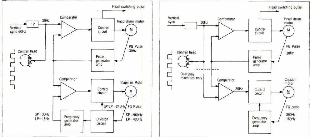
Fig 6 Block diagram of the VHS servo system in record.
Fig 7 Block diagram of a Beta servo system in record.
The servo system
A servo system is simply an electro-mechanical device that permits automatic control over the speed and position (phase) of moveable mechanical parts. A servo system needs two kinds of information in order to accurately control these moveable mechanical parts: It must know what these parts should be doing, and it must know whether these parts stray from a predefined state. To do this it needs two signals: a reference signal (to tell it what the parts should be doing) and a feedback signal (to tell it what the parts are doing).
Modern VCR's, especially those used for editing, put servo systems to one of their most exacting uses. The VCR servo places the video heads on the correct paths and in the correct position to play back a video tape. This function is called tracking. In playback, the servo must switch on the head coming into contact with the video tape and switch off the head leaving the tape. This is head switching. In both tracking and head switching, the servo has to have precise control over the video heads.
In video tape recorders, you'll find a variety of servo control systems, but in VCR's you'll usually find a head servo system, a capstan servo system, or a combination of the two. To operate at all, a VCR must have a head servo, because a television signal cannot be recorded or played back without controlling the head speed and position during these operations. In both VHS and Beta machines the head servo can be either an AC or a DC motor. Single speed, or standard play (SP), VCR's often use a head drum motor that belt drives the capstan, but some VCR's, such as the JVC machines, use separate capstan motors. In dual speed machines (SP and LP) a motor drives the capstan. In both cases, the purpose of the capstan is to transport the video tape at a constant speed during standard play and long play operations.
In some VCR's the capstan servo must also maintain alignment of the recorded tracks and the video heads during playback. An alternate system uses a capstan system that simply keeps the capstan moving at the correct speed and leaves tracking to the drum servo. (This means the head drum must speed up and slow down to make the heads hit the right place on the tape at the right time.) Tracking is necessary to ensure that the signal played back produces an acceptable picture. In all VCR's, slight tracking problems can be overcome by adjusting the front panel tracking control.
A VCR can have three different inputs: a video camera, a television broadcast signal, or another VCR. When recording from a camera, the head servo allows the head drum to produce a stable signal and allows the tape to run at a constant speed. The signals from the frequency generator and the pulse generator coils provide reference signals for the camera so that it synchronizes itself with the video heads. Another method to do the same thing is to have a camera with an independent sync generator that allows the VCR to lock to the camera. A vertical sync pulse always appears when the video head is in the correct position to record it. This vertical sync pulse becomes the control track pulse that controls the servo system during playback.
The other two inputs use the vertical sync pulse for reference signal and for creating the control track pulses necessary for servo control during playback. To write a control pulse on the tape during recording, the servo system takes the incoming 60 HZ vertical sync pulse from the television broadcast signal or another VCR and divides it in half. This 30 hertz frequency is the reference signal that is compared to the pulse generator signal (the feedback signal) coming from the head drum assembly. If the two pulses aren't in phase, the output of the comparator network speeds up or slows down the head-drum motor until the two signals are in phase. A 30 hertz signal (derived from the vertical sync) becomes the control pulse when routed to the control head.
During playback a similar process occurs, except the control pulse is taken off the tape and compared to the signal from the pulse generator. When they're different, the servo motor makes the necessary motor speed adjustments.
Head drum operation
In recording, the servo control system has three functions: 1) It controls the speed and phase of the head drum motor; 2) it controls the position (or phase) of the video heads; and 3) it writes the control pulses on the control track that later becomes the playback reference signal.
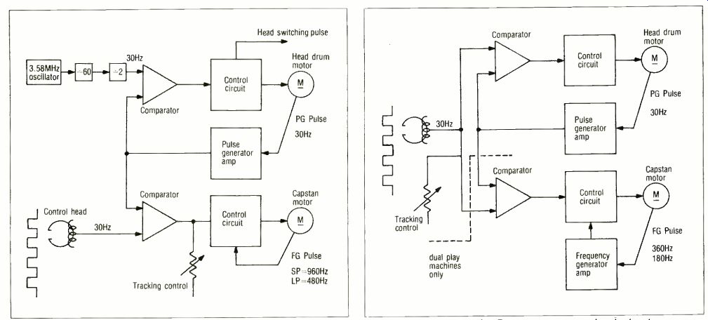
Fig 8 Block diagram of a VHS servo system in playback.
Fig 9 Block diagram of a Beta servo system in playback.
To accomplish the first two functions the servo system uses a pulse generator (PG) pulse created by the pulse generator coil as one or more permanent magnets imbedded in the head drum assembly pass it. In a VCR the head drum motor drives the video heads at 1800 rpm. (Note: 1800 rpm is 30 Hz.) In the head drum assembly of some VCR's (Matsushita's VHS for example), the two magnets are arranged so that one north pole and one south pole are exposed. Then as the head drum spins at 1800 rpm's, the PG coil senses the coming and going of each magnetic field and creates a PG pulse. (See Figures 3 and 4.) Whenever the magnet passes the head coil, video head -A begins its scan of the video tape.
In other VCR's (Sony for example), the polarity of the magnets is unimportant. A magnet sweeps a pickup coil as the A -head crosses the place on the track where vertical sync should lie.
Each PG pulse swings negative and positive. The pulse for the A-head is the mirror image of that for the B-head.
These pulses feed into two monostable multivibrators. One multivibrator triggers on the positive sweep of the signal and the other on the negative. These negative and positive swings set and reset a flip-flop whose output is a square wave used for head switching during playback. As the input to the trapezoidal waveform generator, they eventually control the speed of the head drum motor. The trapezoidal waveform generator shapes the pulses into trapezoidal waveforms that control the head position.
Head position
To control the position of the heads, the PG pulse triggers a voltage ramp (a sampling pulse) that is later compared to a trapezoidal waveform. (A trapezoidal waveform has rise and fall times somewhat slower than a square wave.) In some VCR systems, when the head drum speeds up, the sampling pulse will shift down the trapezoidal ramp. This lowers the voltage output of the sampling gate. If the head drum slows down, the opposite happens. (Fig. 5.) In either case, the speed of the motor adjusts to compensate for the change in head drum speed. When the sampling pulse is compared to the trapezoidal waveform the result is a voltage that varies according to the relative position of the sampling pulse in relation to the slope of the trapezoidal waveform. As this relationship changes, so does the voltage that determines the head drum speed, and therefore the position of the heads.
Frequency pulse
In addition to the PG pulse, the dual speed machines use a frequency generator pulse as a feedback signal.
This signal is picked off the head drum motor and is proportional to the speed of the head drum. Its frequency, however, depends upon which mode (SP or LP) the machine is in.
In most VHS systems, the head motor produces a frequency generator (FG) pulse. In the Beta systems, only the dual play machines have an FG pulse. In either system, when it comes off the head drum motor, the FG pulse aids the trapezoid waveform derived from the PG pulse in controlling the head drum motor speed. When it comes off the capstan motor, it helps control the capstan motor speed. When either motor runs too fast, the FG pulses increase. Then, after they're fed back to the motor brake, the amount of inductive reactance drops and the motor speeds back up until it reaches its normal operating speed.
Control track pulses
In record, the incoming vertical sync pulse is processed so that when it's applied to the control head, the control head writes a 30 Hz control pulse (a square wave) with 50% duty cycle on the lower edge of the video tape. (Although it's convenient to think of the control track pulses as square waves, they're really amplitude modulated sine waves.)
Capstan servo
The head motor is the main motor in a VCR servo system. It locks to the capstan either mechanically by a drive belt, such as in the single play Beta systems, or electronically by a trapezoidal pulse as in Beta and VHS dual speed systems.
The capstan, regardless of how it's driven, maintains a constant linear tape speed and a constant tape position. It aids in aligning the tape with the incoming video or camera signal for editing. To accomplish this the tape speed must be varied until the vertical sync pulses on the tape and those of the incoming video signal align. The capstan also controls the longitudinal motion of the tape so that the rotating heads follow the center of the pre-recorded tracks during playback. A detailed description of the Beta and VHS servo system, which follows, will tell you more about the capstan.
Recording with VHS
The RCA VHS servo system assures that there is always a 20 micron guard band in standard play, a 10 micron track overlap during long play, and that the vertical sync pulse occurs at the ninth horizontal line from the beginning of each track. (See Fig. 6.) In order to lock to the vertical sync pulse, the head drum motor rotates at 1798.2 rpm, a speed derived from the 59.94 Hz vertical sync rate of the color video (59.94Hz 2 video heads x 60 seconds = 1798.2 rpm.
A divide by 2 circuit steps down the vertical sync signal to 30 Hz and applies this signal to the control head to establish the 30 Hz control track reference signal. The pulse generator signal coming off the permanent magnets in the head drum assembly contains both positive and negative going pulses. The amplitude of these pulses is too low to be directly used.
The PG amplifier brings them up to a useable amplitude. Then after a short delay, the PG pulses set and reset a flip-flop whose output is a square wave that controls head switching. A second output from this flip-flop goes to the head sampling gate and to the capstan sampling gate after being shaped by a trapezoidal waveform generator.
The head sampling gate compares the trapezoid waveform to a sampling pulse derived from the vertical sync input. The output of this block supplies a voltage to the speed control and the head motor drive block, and finally to the head motor, which drives the head drum. The voltage output of the head sampling gate depends upon the relationship between the trapezoid and sample waveforms, in the manner already discussed.
Recording with Beta
Two basic types of older model Beta servos exist, those designed to operate at only one speed either SP (1 hour) or LP (2 hours) and those designed to operate at both these speeds.
Two types of Beta recorders have servos from the first group. Those recorders, based on the Sony 6200, 7200, and 7200A design, operate in the SP mode only; and those designs based on the Sony 8600 operate in the LP mode only. Beta dual speed machines base their design on the Sony 8200.
Because a discussion of this machine covers all of the Beta servos, we'll use it as an example.
The major difference between the dual speed and single speed Beta recorders is that the dual speed Beta VCR's drive their capstans with a DC capstan motor, while the single speed VCR's belt -drive their capstans, which eliminates some of the servo electronics.
A divide -by -2 circuit (Fig. 7) steps down the 60 Hz incoming vertical sync to the 30 Hz signal, which, after some amplification, becomes the control track signal used during playback. This stepped down vertical sync signal becomes the sampling pulse, controlling the position and speed of the head drum and capstan.
Permanent magnets in the rotating head drum generate signals in the A and B pulse generator pickups that other blocks amplify and delay. The outputs of the A -PG amplifier and the B -PG delay, set and reset a flip-flop which produces a square wave used for head switching. A trapezoidal waveform generator shapes the output of the A pulse generator delay and feeds it to the head sampling gate.
Here the 30 Hz pulse samples the trapezoidal ramp and produces a voltage output that's determined by the relationship between the two waveforms. This output then adjusts the phase and speed of the head drum motor so that it always runs at about 1800 rpm.
The 30 Hz signal also acts as the sampling pulse for the capstan servo electronics. The frequency generator pickup signal is formed into a square wave and amplified. It becomes the capstan speed feedback reference and the trapezoidal waveform determining the capstan motor speed. The capstan sampling gate determines its output voltage according to the relationship between the sampling and trapezoidal waveform just as the head drum sampling gate did.
Four functions
The servo system has four functions in playback: 1) It keeps the head drum and capstan at a constant speed; 2) it controls the occurrence of head switching; 3) it keeps the video heads on the pre-recorded tracks; and 4) it picks the control pulses off the control track.
The first two functions are handled just as they are during video recording.
However, during record the VCR uses the incoming vertical sync pulse as a reference signal. During playback, this signal is gone. So, in order to maintain the same control, another signal must be substituted.
In VHS (Fig. 8) recorders a 3.58 MHz oscillator provides the reference signal for the head drum motor during playback. This 3.58 MHz signal is counted down to a 60 Hz signal which is used during playback in the same way as the vertical sync pulse is during recording.
When it's recording, the VCR uses the vertical sync pulse to create control pulses on the lower edge of the video tape. When a VCR plays back a tape, the control head takes these pulses off the tape. They become the reference signal which controls the phase and speed of the video heads and capstan.
(In the case of a tracking capstan servo, the control pulses don't control the phase of the video heads, which run free, but only the capstan. The capstan makes the tape get into the right place at the right time.) In Beta (Fig. 9) recorders, they are the main reference signal for both the head and capstan motors, while in the VHS recorders, they're only the capstan reference signal.
In both cases, this reference signal is compared to the PG pulse. When the reference signal and the PG pulse are synchronized, both the rotational speed and the phase (position) of the heads are identical and playback operation is stabilized. If one of the two pulses being compared should be lost, you'll be able to hear the servo motor speed up to try and find it.
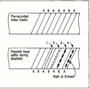
Fig 10 Of these possible video head paths, only path one will give optimum
output.
Path two will give a reduced output; path three will give noise and a partial output.
Path four (B -head reading on A -track) will give only noise. Mistracking is caused by the control signals being played back too early or too late.
==========
TABLE 1

Common Servo System Problems:
Head drum motor runs erratically or hunts
Servo speed increased after machine is run for a while
Monitor picture is noisy, bent, and flagging
Intermittent video in playback
Increased capstan and tape speed
Monitor picture tearing
Donald Duck voices and rapidly moving figures
Playback exceptionally noisy
Noise bar through picture
Pre-recorded tapes won't playback
Head switching at wrong point
Servo drive belts stretched
==========
Head switching
To have continuous playback, the two video heads are alternately switched on and off. This is accomplished by switching the first stage of each pre -amplifier on and off according to which head is scanning the tape.
Usually, a switching transistor controlled by the head switching pulse turns the pre -amplifiers on and off. This prevents excess noise from appearing in the video display.
The point at which head switching occurs is critical. If it occurs prior to the vertical interval, head switching is barely discernable in the video display. The only evidence of its occurrence is a slight misalignment of the first few horizontal lines of video with the previously displayed video lines. If head switching occurs in the back porch of the vertical interval, it causes noise in the black bar of the vertical blanking which you can see by adjusting the television vertical control. Of course, this hurts nothing.
To avoid video dropouts during head switching, most two headed video recorders wrap the tape around the video head drum more than 180°.This allows both heads to come in contact with the tape for a short time. Such simultaneous contact prevents video signal drop outs.
Tracking
Obviously, the video heads must follow the recorded paths identically during playback. In addition, because of the different azimuths of the two heads, a head can only reproduce those tracks recorded at the same azimuth. If it doesn't, there's no video output.
The guard bands used in standard play (SP) recording can allow some degree of mistracking without a severe loss in output. But when the tracks are adjacent in either the VHS or Beta format, tracking must be exact. Crossing over two or more track edges creates noise bands on the monitor screen.
The control track pulses identify one of the heads as a reference head.
Whenever the VCR picks up a control pulse, it knows that it's reading the A -track, for example. If the wrong head is reading a track the head speed increases until the reference head locks to the control track. The occurrence of the control track pulse indicates that the vertical interval on the tape is in the correct position for playback.
The tracking adjustment on the front panel compensates for most minor tracking problems. But if the tracking adjustment should need major adjustment, follow the directions listed in the service manual for that model.
In VHS playback, most of the process is the same as that during record. One exception to this is that the reference signal is not the vertical sync, which isn't present during playback, but the stepped down output of a 3.58 MHz oscillator. Except for the difference in reference signals, the control of the head drum position and speed is virtually the same as it is during the record operation.
Control of the capstan speed and position is, however, somewhat changed. The control head picks up the control track pulses referencing the head position. A control pulse amplifier brings the control track pulses up to a useable amplitude. The front panel tracking control adjusts the output of the control pulse amplifier to compensate for any tracking problems.
The trapezoid waveform derived from the PG pulse is applied to the capstan sample gate and controls the position and speed of the capstan motor.
Troubleshooting
Taking the time to know the VCR you're working on can save you hours of troubleshooting time. For instance, when you discover an audio problem, don't limit your thinking to just the audio block. Sometimes audio problems are caused elsewhere. This is especially true when an audio problem is accompanied by other symptoms.
"Donald Duck" voices and rapidly moving figures on the monitor screen probably indicate a capstan servo problem rather than an audio problem.
So, if your troubleshooting of a suspected audio problem reveals an operational audio block, don't be alarmed. The problem is probably somewhere else.
Check some other places. The loss of a few control pulses could cause your audio problem. The buzz in the audio might be due to a bad antenna connection, or a misadjusted VHF modulator. With an audio problem, be sure that you examine the video symptoms. Oftentimes they will lead you to the real problem.
Of course, the audio block can have problems. A consistently low audio output might mean that the audio head needs alignment. An audio head that has a height misalignment can reduce the audio output by as much as 50%, but misalignment of the azimuth would reduce the high frequency response.
Fluctuating audio tends to be a "wow and flutter" problem caused by poor tape flow past the audio head.
Servo problems Servo problems show up in both playback and record. For this reason, VCR technicians like to have the playback section operating before worrying about the record section. The symptoms of servo problems are often simple-a good tape just won't play back correctly, if at all. Something as simple as a loose drive belt can prevent the servo from locking onto the control track pulse. Even something as remote as static on the drive belts can hamper perfect video reproduction. In some ways, the servo system is probably the most complex block of the VCR. At first glance it appears to be a mad designer's nightmare. But with a thorough understanding of the basic operational principles given here, the experience of finding servo problems, and several trips through the servo information of the service manuals, you'll awaken from the nightmare.
Power problems
Power supply problems frequently appear as no control lights, dim or flickering control lights, lack of tape movement, failure to load a cassette, no video or audio, and lack of head drum rotation. Checking for power supply faults isn't hard. Besides doing the usual checks (i.e. visually checking for blown fuses, burnt wiring, etc.) a general purpose oscilloscope is an excellent tool for troubleshooting power supplies. The general purpose oscilloscope can be used to do such things as meter the incoming line voltage or to locate power supply transformer problems.
In this article we have concentrated primarily on servo mechanism operation, traditionally one of the least understood, yet most troublesome, of all the sections of any VCR. In our next article we will dig into the function and operation of the luminance and chroma blocks.
---------
Also see: A sound future in audio--Digital is on the way
= = = =