(source: Electronics World, Jul. 1963)
By ABRAHAM B. COHEN, Executone. Inc., Chief Electro-acoustic Engineer
Principles and practical applications of this important and widely used p.a. hookup system that permits simple adjustment of loudspeaker power without considering impedance matching.
THE constant-voltage sound-distribution system is an extremely useful aid to the sound-system installer and technician. Advantages of the constant-voltage system include: (a) easy, on-the-spot sound-power adjustment of loudspeakers without worrying about impedance matching on the line as a whole, and (b) conservation of audio power.
The constant voltage system also assures that the installation is not an electrical hazard. Section 640.5 of the National Electrical Code states the following with respect to an audio distribution system:
"640.5 Conductors: Amplifier output circuits carrying audio-program signals of 70 volts or less and whose open circuit voltage will not exceed 100 volts, may employ Class 2 wiring as covered in Article 725.
"The above is based on amplifiers whose open-circuit voltage will not exceed 100 volts when driven with a signal of any frequency from 60 to 100 cps sufficient to produce rated output (70.7 volts) into its rated load. This also accepts the known fact that the average program material is 12 db below the amplifier rating--thus the average r.m.s. voltage for an open-circuit 70-volt output would be only 25 volts." The graphical presentation of these audio line voltages is shown in Fig. 1. By meeting these standards, the requirements for installation and wiring are far less stringent than in the case when higher voltages, such as those of a.c. power lines, are employed. Hence audio wiring need not be enclosed in conduit or BX to meet Underwriters' approval.
The constant-voltage distribution system is as simple to use for sound networks as is the 117-volt a.c. power utility system. We plug a 100-watt lamp into an electric outlet to get bright illumination or a 15-watt lamp into the same power line for low illumination. See Fig. 2A. The user knows that all he has to be concerned with is how much light he wants in any particular location, and he chooses a bulb rated in power accordingly. The power is very clearly marked on the light bulb. It isn't necessary to figure the lamp's impedance. For a constant-voltage (70.7 -v.) sound-distribution line, transformers are used that are marked directly in watts.
If one wants a lot of sound (see Fig. 2B), he might connect the loudspeaker-transformer combination to the 30-watt taps.
If, on the other hand, he is after just background-level sound, he may choose the transformer input terminals marked "3: watt." Impedances are automatically taken care of by the transformer design and the manner in which the transformer is connected to the loudspeaker.
In the case of an 8-ohm speaker connected to the 8-ohm output terminals of the transformer, we just match numbers at the secondary. But the input or primary terminals of the transformer will be marked in watts, say 10, 5, 2.5, 1.25. We simply connect the line to the appropriate wattage tap on the transformer primary to give us whatever sound power is necessary to cover the area effectively. In most cases, then, changes in power to the loudspeaker may be made quickly by simply changing the prim: n connection to the transformer without considering impedance problems in any way.
How the System Works
The foregoing doesn't mean, however, that transformer impedances are forgotten. While most transformers designed for the constant-voltage system specify the primary taps in terms of power, there are some transformer manufacturers who still rate their sound-distribution transformers in primary impedance instead of watts. From the following discussion we will show how to convert one notation to the other for power-adjustment purposes.
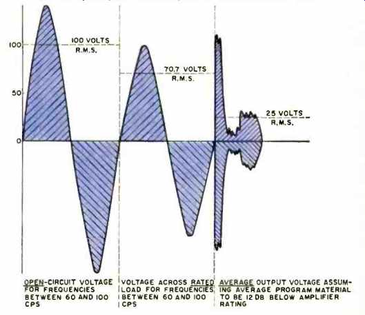
Fig. 1. Graphical presentation of audio line voltages in a 70-volt system,
as defined by the National Electrical Code.
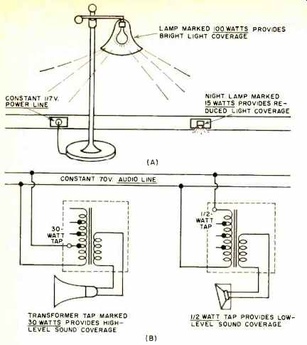
Fig. 2. Comparison of 70-volt audio line with 117-volt a.c. power line showing
the ease of meeting required power needs.
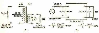
Fig. 3. An ideal transformer transfers power from a generator of one impedance
to a load of another impedance, without any loss, by means of the impedance
ratio of two windings used.
In an audio-distribution system, a transformer transmits power. This power transfer is usually from a source of one impedance to a load of a different impedance. Fig. 3A, for example, shows a step-down transformer accepting power from a high-impedance source, such as the plate circuit of a tube of perhaps 5000 ohms, and transferring that power to a low-impedance load, such as an 8-ohm speaker. Assuming an ideal loss-less transfer device within the black box of Fig. 3B, we know that for maximum power transfer to the 8-ohm load, power must be fed from an 8-ohm source. Thus if the tube is delivering an output of 50 watts and the loudspeaker is receiving 50 watts, then the ideal box with its "transfer unit" inside is actually transferring (or transforming) a 5000-ohm impedance from the left to 8 ohms on the right.
The measure of this impedance transfer is the ratio of these two impedances as seen, respectively, by the generator and by the load. When fully connected, the secondary winding "sees" the load impedance of 8 ohms. Now this 8-ohm impedance is stepped up to, or transformed to, the higher primary impedance, which "sees" the 5000 ohms of the source.
The system is now matched on an impedance basis for maximum transfer of power to the load.
In reality, the voltage across the "70-volt" constant-voltage line is 70.7 volts for a very simple reason. Power across an impedance is P = E2/Z: thus in the "70volt" system P = (70.7)2/Z = 5000/Z. This figure of 5000 makes it very easy for us to select a transformer input impedance to accept any power we want and, on the basis of an even figure of 5000, mark the input impedance terminals in power.
Let us assume that we want to deliver one watt of power to an 8-ohm speaker, using the transformer shown in Fig. 4A. The simple calculations accompanying this figure show that to transfer one watt from the line side to the load side of the transformer, the input impedance of the transformer will have to be 5000 ohms. For 2, 4, and 8 watt transfer, the input impedance taps would vary according to the simple tabulation shown. These various taps may then be simply marked with their corresponding power-acceptance number, as in Fig. 4B. But, it must be remembered that this numbered notation of the primary in terms of power will hold only for a 70.7-volt feeder line and when the secondary impedance figure is matched to the corresponding speaker impedance.
The transformer shown in Fig. 4B may then be used directly without any additional calculations for drawing as much audio power from the line as desired and in whatever steps are desired (usually in steps of 3db double the power) up to the capabilities of the amplifier. In a noisy location it may be necessary to connect the transformer as in Fig. 4C under which condition the loudspeaker will draw the power marked, 8 watts. Note that the equivalent impedance of the 8-watt input, which one doesn't have to worry about, is 625 ohms.
Normally, then, the constant-voltage transformer will have the secondary marked in terms of the speaker impedance, and the primary winding will be marked in terms of power. If, however, one should run into a line transformer with impedance markings as in Fig. 4A, embracing the familiar figures of 5000, 2500, 1250, 625, and so on, one may be fairly sure that the transformer is intended to be used on constant-voltage systems. The corresponding equivalent power rating of these taps may then be determined from P = 5000 /Z.
Uses and Misuses of the System
The great advantage of the constant-voltage sound-distribution system is that it eliminates the purely electrical design problems of multiple speaker mesh network impedances for the sound-system installer. This leaves the sound man free to concentrate on providing specified audio power as required by the ambient conditions. A second, but very important aspect of the constant-voltage system for the distribution of audio power is the saving of that expensive commodity--audio power. When using 70-volt transformers for power tapping, the only losses in the system are line and transformer losses. However, when using an attenuation system of line-level control, power is wasted in the various resistive elements that go to make up the pads. In an extensive sound distribution system where there may be as many as thirty or forty speakers with attenuator-type controls, considerable audio power would be thrown away in the form of heat rather than made available as useful reserve power.
While it is true that the sound man may hook loudspeakers indiscriminately across the constant-voltage line (using the proper transformers, of course), he is nevertheless limited by the total audio power available to him. He may tie on as many loudspeakers as he pleases just as long as the wattages he has selected for each do not add up to more than the power rating of the amplifier.
If one throws too many speakers across the line, the amplifier is loaded down too much, the constant-voltage characteristic begins to droop, and the over-all sound level goes down.
When this happens, usually someone turns up the gain of the amplifier in an effort to return the sound level to normal. But what actually happens is not more output but more distortion from an already overdriven or overloaded amplifier. This makes the amplification system sound even worse, and eventually, it may also cause the output tubes, rectifier, as well as associated components to fail.
Amplifier Considerations
It is not possible to take any amplifier and simply load it down with constant-voltage transformer-loudspeaker combinations unless the amplifier is designed for such operation.
Such a condition can be obtained only in amplifiers with heavy overall negative feedback and with as low an internal impedance (at the output terminals) as possible.
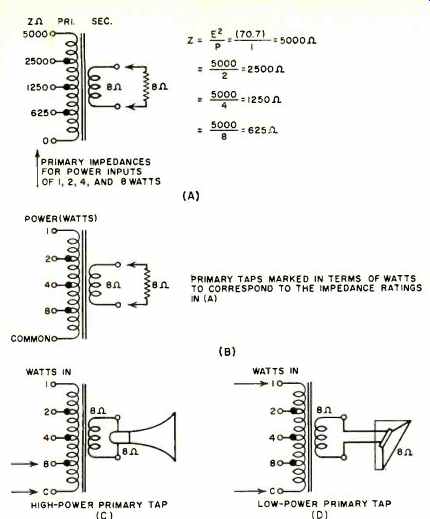
Fig. 4. Correspondence between impedances and power ratings.
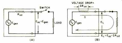
Fig. 5. The internal resistance of a generator develops a voltage drop that
reduces the terminal voltage when current is delivered to the load. Constant-voltage
generators must have the lowest possible amount of internal resistance.
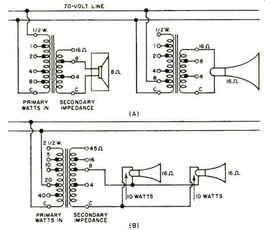
Fig. 6. With a tapped secondary, added versatility is achieved.
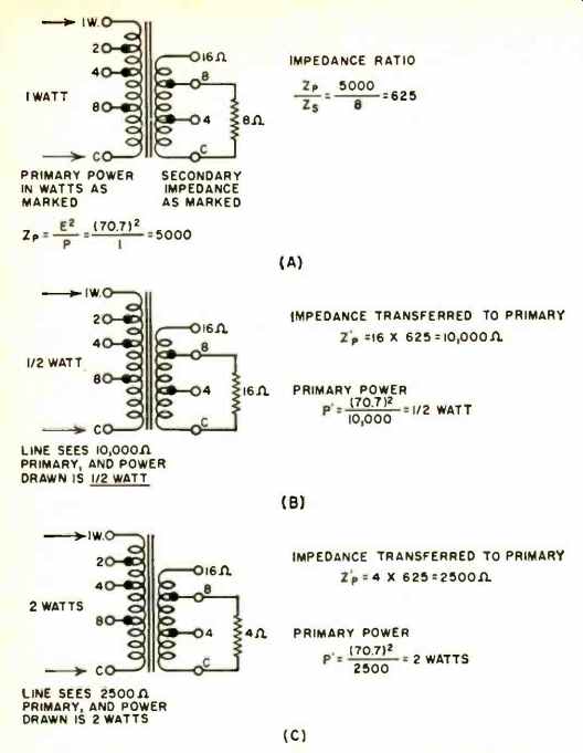
Fig. 7. Effect on power drawn of changing the value of the load.
An amplifier, like any power generator, has some degree of internal resistance. A flow of electrical current cannot be obtained without that flow, of necessity, traveling through the generator itself (Fig. 5). In traveling through the generator, the current must travel through the internal resistance of the generator itself. There will be a voltage drop across the internal resistance equivalent to IR_int which will drop the generator's terminal voltage. As the load demands more current, the higher will be the voltage drop across the generator internal resistance and the lower will be the terminal voltage across the load. Thus we see that if we want the terminal voltage to remain as constant as possible, then the amplifier (generator) should have the lowest possible internal impedance since this will keep the internal voltage drop correspondingly low.
The ideal constant-voltage generator or amplifier should have zero internal impedance. This condition is, of course, physically unrealizable. But, with the help of properly designed feedback systems, the internal resistance can be kept low enough so that the unloaded voltage rises no more than 3 db over the fully loaded voltage. Such an amplifier, having a loaded output voltage of 70 volts and an unloaded output of no more than 100 volts, falls within the amplifier characteristics outlined by the National Electrical Code at the beginning of this article.
Setting the gain of the constant-voltage amplifier has sometimes been not too well understood. The gain of the amplifier, once set properly, should be left alone irrespective of the load power it is called upon to deliver. The amplifier gain is set so that, when the amplifier is driven by a predetermined input, such as one volt, then it will deliver its full undistorted potter to its load.
As an example, suppose the amplifier is rated at 50 watts and it is to deliver 70.7 volts to the distribution line. Then the full-load impedance should be Z = E2 /P = 5000 /50 = 100 ohms. With a 100-ohm resistor rated at a minimum of 50 watts across the output of the amplifier and with the amplifier fed a constant frequency signal such as 1 kc. at an amplitude of one volt, the gain should be adjusted so that an output voltmeter across the load resistor reads 70.7 volts. When this is accomplished, the gain control of the amplifier should be locked down and left untouched.
A question may arise as to why the amplifier is adjusted to deliver a full 50 watts when all that is necessary for a particular coverage is, say, 20 watts. The answer is quite straightforward. The amplifier delivers only what it is asked to deliver by the load it sees. If the speaker transformer primary is tapped for only 1 watt, and that is the only load on the system, then the amplifier will deliver only 1 watt, even though the gain control is set for the potential delivery of 50 watts. The amplifier is standing ready to deliver power only as called for by the load, up to the limiting capacity of the amplifier that is used.
Transformers with Tapped Secondaries
The usual constant-voltage transformer has, in addition to its primary tapped in terms of power, a secondary with several impedance taps, such as 4, 8, 16, or 45 ohms. Obviously this permits a wide variety of loudspeakers of different impedances to be integrated into one system. This allows a hookup such as that shown in Fig. 6. Here an 8-ohm cone speaker is tied on to the 8-ohm secondary tap of the transformer with the primary set at, say, 30-watt input. At the same time a 16-ohm outdoor trumpet is connected to the 16ohm secondary of its own transformer with the primary tapped for perhaps 8 watts. In a case like this, the great simplicity of the constant-voltage distribution system shines forth.
Suppose we were to try to lay out this system on an over-all impedance basis. Whether you try to arrange the two speakers in parallel, which would result in a combined impedance close to 5 ohms, or in series with a combined impedance of 24 ohms, where do you find a transformer with these output impedances? But, more important, if we set the gain control of the amplifier so that 8 watts is delivered to the 16-ohm trumpet, then (assuming the 8-ohm speaker is in parallel with it), the 8-ohm unit would draw twice as much power as the 16-ohm unit, or about 16 watts, when all we want in this unit is watt. Obviously, then, we have to put some type of volume control unit ahead of the 8-ohm speaker to soak up and waste, as heat, several watts of precious audio power.
Still another advantage of the transformer with a multi-impedance secondary is that small branch circuits or groups of similar loudspeakers can all be fed from one transformer.
As shown in Fig. 6B, if a given distributed sound layout is specified where one has to use two 16-ohm trumpets, they may be connected in parallel across one transformer using the 8-ohm secondary tap. Now if it is required that each speaker deliver 10 watts, then the 20-watt primary tap would be used. This, then, would draw 20 watts from the amplifier to be distributed equally between the two units. If, however, the speakers in one small group are not of the same impedance, or are not expected to draw equal power, then give each speaker its own power matching transformer.
Transformer Versatility
Let us see how much more versatile the multi-impedance transformer may be beyond those ratings shown on the transformer itself. Despite the actual markings on the secondary, we can arbitrarily give them any rating we want. This is provided that, if we change the "specs" on one side to suit our purpose, we change the other side accordingly, and that we do not exceed the maximum power rating of the transformer. Refer to Fig. 7.
When the 8-ohm secondary is loaded with 8 ohms and the primary is tapped for 1 watt, then the primary impedance is Z = E^2/P = 5000 /1=5000 ohms. The impedance ratio of the transformer for the condition given is 5000/8 = 625.
Now let us forget that the secondary is marked 8 ohms or that the transformer tap is marked 1 watt. What we will simply deal with is the fact that between these two windings we have an impedance step-up from load to source of 625.
With this in mind, let's hook a 16-ohm speaker load across the 8-ohm tap on the secondary winding. All that the transformer now knows is that it is loaded down by 16 ohms and that it must transform this upwards by a factor of 625. Thus the primary tap will now look like 625 x 16-10,000 ohms to the amplifier. Now the 70.7-volt line from the amplifier will be loaded down not by 5000 ohms but by 10.000 ohms, and the power drawn from the line will now be P = E ^2/Z = 5000/ 10,000 = 'z watt. We see then that doubling the impedance of the load will cause only half of the specified primary tap power to be delivered to the loudspeaker load.
Going in the other direction, if we connect a 4-ohm load across the 8-ohm secondary tap, we will end up with a primary impedance of Z = 625 x 4 = 2500 ohms. Accordingly, the power drawn from the amplifier will be P = E^2 /Z = 5000 /2500 = 2 watts. In this case, the load impedance has been halved and the input power to the transformer primary tap marked "1 watt" has been raised to 2 watts.
From the foregoing, we may generalize as follows: If the load presented to the secondary is K times the impedance specified for the tap to which the load is connected, then the power drawn by the primary will be 1/K of the power indicated by the tap to which the line is connected. This formulation is summarized in the table of Fig. 8.
Other Voltages
In addition to the popular 70.7-volt system, there is also a 25-volt system and a 141-volt system. The 25-volt system is sometimes used in schools and institutions where a maximum of safeguards against hazardous conditions is required.
On the other hand, for lines extending over long distances, the 141-volt system may be used. With such higher line voltage, line currents for a given power will be reduced for quite a saving in copper in the initial installation, and in power losses in the line during actual operation.
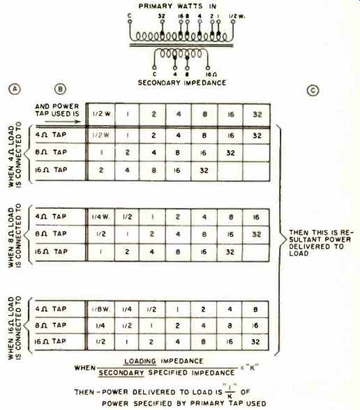
Fig. 8. Tabulation of power with various output connections.
However, for audio-distribution work, the 70.7-volt system is by far the most common. It permits an economically installed system since for this voltage level conduit runs are not required by the National Electrical Code. For some permanent installations, however, neatly installed conduit would certainly be more professional and more desirable.
The same general basic considerations concerning load impedances and input power hold for all three systems mentioned, namely: For the 25-volt system, P = E^2 /Z = 25^2/Z = 625/Z For the 70-volt system, P = 70.7^2/Z = 5000 /Z For the 141-volt system, P = 141^2/Z = 20,000 /Z And similarly, the same K and 1/K factors hold for the three systems.