|
|
(source: Electronics World, Nov. 1971)

By FOREST H. BELT
Linear IC's are popular in color sets this year.
Here's how to check them for proper operation.
ABOUT five years have passed since the first linear integrated circuit was used in a television receiver. In all that time not much has been published to help technicians service them. The established procedure has been: If you suspect one, try a replacement.
But that's haphazard. And, besides, it costs money. Who wants to carry an inventory of IC's just for making substitutions? It is far better to know how to test them.

Fig. 1. A large number of integrated circuits are now showing up in consumer
products. Besides TO-type shown here, flat pack IC's are used with their
connections in-line along sides.
If you've kept up with what's in 1971-model color receivers, you know how popular IC's are. (Editor's Note: See the January, February, and March 1971 issues of ELECTRONICS WORLD.) Sixteen different brands have integrated circuits in them, from Admiral to Zenith. Quite a few black –and-white sets use them, too (Fig. 1). IC's are used several ways. By far the most popular is an integrated-circuit sound section. in fact, that was the first use ever made of an IC in television. RCA put the first home-electronics IC into the sound section of one color chassis in June, 1966. Throughout the next three years, that was the only purpose for which any company used IC's.
Second most popular now is the integrated-circuit chroma demodulator. Zenith kicked off this application only a couple of years ago. Since then other set makers have followed suit. And more brands will have IC demodulators next season.
About the biggest IC news in 1971 models was that made by Zenith. Two basic Zenith color chassis--one all-transistor and the other a mostly' transistor hybrid-have an all-IC chroma section. Actually, the only other active components in the whole color section are three transistors that amplify color-video outputs.
With so many integrated circuits popping up, it must be obvious that the TV technician has to learn to service them efficiently. Don't fret. They're not as impossible to test as their small size and complex inner-workings might lead you to believe.
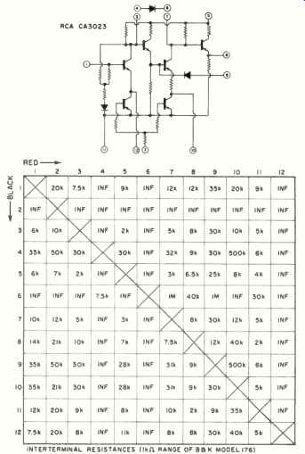
Fig. 2. Sample chart of internal resistances, measured from terminal to terminal.
Resistances depend on which lead is connected to each terminal, but this chart
takes that into account.
Active Tests for IC's
There are three practical ways to check any IC.
1. You can check its d.c. operation. At least one supply voltage is fed in. Usually, a regulator section inside the IC cuts the input voltage to whatever level is needed by the transistor amplifiers on the IC chip. Voltages are dropped across transistors and resistors in the IC. The result is reduced voltage at some terminals. If those voltages are wrong when measured, it indicates trouble inside the IC. Also, there's usually a series resistor between the d.c. supply voltage and the d.c. input terminal of the IC. If the voltage drop across that resistor is too high, the IC may be drawing too much current. If the drop is too low, the IC may not be drawing enough.
2. You can check signals fed into the IC and those coming out. Because of necessary external components, signals may go in and go out several times, in various forms. What you do is supply the normal signal to the first input and then test outputs at succeeding points. If an output is incorrect or missing, that section of the integrated circuit is likely to be at fault.
3. You can check tuning of associated resonant circuits.
When you're troubleshooting any section of a TV receiver, tunable coils can offer a valuable clue to operation. They can also tell you whether a fault is in the active elements of the section (the IC, in this case) or in passive components. A quick run-through of any adjustments-coil or potentiometer-in an LC section is another way to verify IC operation.
There's a fourth way, too. It's called passive testing. For technicians, it's not very practical. It requires a detailed knowledge of what is inside each IC. What you do is measure between terminals with an ohmmeter. If you know what value of resistance should appear between each of them, or between certain key terminals, you can evaluate whether a section of the IC is defective or not.
There are no lists of values for various IC's, not even in manuals some manufacturers publish. But you can compile your own list for an IC type you work with very often. Just take one you know is okay, get it out of the circuit, and measure resistance between various leads. Check them with your ohmmeter leads in both polarities and chart what you find. First chance you get, repeat it with a couple more good ones of the same type. Then you'll recognize any normal variations.
The sample chart in Fig. 2 is for one IC. Actual values depend on what model ohmmeter you use, polarity of its internal battery, and which range you use.
You may also find substrate leakage that confuses certain readings. An example is terminal 4 in Fig. 2. There is some leakage to terminal 11-- about 6k ohms-- when the black lead is on 4. Resistance from 4 to 9 is also low, but that's because of a low-value resistor (about 3k ohms) between terminals 8 and 11 inside the IC. Terminal 4 is supposed to be isolated, according to the internal diagram of the IC. That this leakage is in the substrate is verified by the diode nature of the leakage; when the red test lead is on terminal 4, it reads infinite as it should to all but terminal 6.
Because of complications like these, active testing is quicker, handier, and more dependable. Leakage such as described above may not hinder performance. Also, unsoldering some IC types is a real chore and presents the possibility of damage from heat. Easiest testing is with the IC right in its circuit and operating.

Fig. 3. External components for sound-section integrated circuits are similar
in most brands. That makes stage-to-stage signal tracing probably the most
dependable testing procedure.
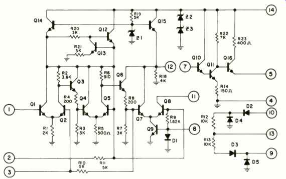
Fig. 4. Internal diagram of IC used for sound section in Fig. 3.
Integrated Sound Sections
There are strong similarities among brands that use IC's in the sound section. These include Admiral, Andrea, Heath, MCA, Midland, Motorola, Packard Bell, Panasonic, RCA, Sony, Sylvania, and Zenith. The integrated circuit usually includes sound--i.f. (4.5 MHz) amplifier, diode sound detector (usually ratio type), and audio preamp.
Internal connections vary widely, even among IC's in different models of the same brand. But operation is so alike, once you understand how to evaluate one, you can test your way through any of them.
The IC sound section in Fig. 3 is typical. The integrated circuit has three major sections. Compare the terminal connections of the external components in Fig. 3 with the internal diagram of the IC in Fig. 4. You'll find the circuit connections to the IC chip are similar for any IC sound section; only the terminal numbers are different.
The secondary of T301 applies 4.5MHz sound i.f. signal between pins 1 and 2 of this IC. Pin 2 is held at r.f. ground by a capacitor. Q1 inside the IC (Fig. 4) gets the sound i.f. signal. The base of Q5 is the other side of a differential amplifier, held at ground by resistor R11 and the external 0.01-µF capacitor.
Differential amp Q1 through Q5 amplifies the 4.5-MHz signal. It then goes to differential amp Q6 through Q9, is further amplified, and fed to terminals 11 and 12. They are the output terminals of the first IC section.
The sound i.f. signal goes to the primary of discriminator transformer T302. The secondary of T302 applies the signal to terminals 9 and 10 of the IC. Inside the IC, those terminals connect to a diode-bridge ratio detector.
That demodulates the FM sound from the sound i.f. Audio is taken from terminal 13.
Volume and tone networks feed the audio to terminal 7. That's the input terminal for the final section of this IC. On the chip, a Darlington amp (Q10, Q11) and emitter-follower (Q16) amplify the audio. Audio-output terminal 5 feeds the signal to the output transistor in the receiver.
Terminal 14 of the IC is the power-supply input terminal.
An external resistor drops the d.c. supply voltage to whatever level is set by Z2, Z3. Transistors Q12 through Q15 and zener diode Z1 regulate d.c. power for the various stages of amplification.
Terminal 8 goes to the second differential amp in the i.f. section of the IC. It permits grounding the base of Q9, thus disabling the i.f. amp and blocking the sound i.f. signal.
That's so sound can be muted while the tuner rotates in remote-controlled operation.
The methods of servicing this IC must be fairly obvious.
If you're using the signal method, you can do it by tracing or by injection.
For tracing, use a 4.5-MHz signal modulated with an audio note; inject it across the detector diode (CR302 in Fig. 3) load resistor. If T301 is okay, the tracer's demodulator probe should detect the audio signal at terminal 1 of the IC. The same signal should appear, much amplified, at terminal 11. It should also be present at terminal 12, since the end of the discriminator transformer is not grounded. If T302 is okay, the amplified signal should be found at terminals 9 and 10, too.
You don't need the demodulator probe for the tracer at terminal 13. Audio there won't be particularly strong (unless you are using a signal generator with FM tone instead of the usual AM). Touch the tracer to terminal 7; that lets you check the action of the volume and tone controls. You should find a considerably amplified audio note at terminal 5 of the integrated circuit.
If you choose the tuning method of checking the IC, use a 4.5-MHz signal, frequency modulated, or station sound. Or, if you're familiar with sweep alignment, a response curve can tell you plenty about operation and tuning. Make the three adjustments--peaking T301 and the primary of T302, then tuning the secondary of T302,for clearest station sound. If T301 doesn't respond to adjustment, it or the first differential amp in the IC is likely bad. If T302 primary doesn't respond, suspect the coil or the second differential amp. If the secondary of T302 doesn't respond, suspect the coil or the bridge diodes.
The d.c. testing method is dependable, too. The voltage at terminal 14 lets you know that Z2, Z3 (both in the IC), and series resistor R306 are okay. If the voltages at terminals 2 and 12 are okay, the rest of the regulator inside the IC is all right. Wrong voltage at terminal 2 could mean trouble in the first differential amp. Incorrect voltage at terminal 7 or 5 means trouble in the audio preamp. Terminal 13 could have a wrong voltage if there's trouble in the detector circuit.
Voltages at certain terminals are brought there mainly by external components. For example, the 4.8 volts at terminal 11 is carried there by the winding of T302; likewise the voltages at terminals 9 and 11. The d.c. voltage at terminal 1 comes from terminal 2 through the winding of T301. Facts like these are important to notice in case a coil opens.

Fig. 5. Three flat-pack in-line IC's contain all the active elements of Zenith
chroma section. For terminal numbers, look at the IC from the top with the
large dot or notched end down. Count up right side of IC and down left side
in counterclockwise direction. From bottom of the IC, pins are numbered in
a clockwise direction starting at notched or dot end.

Fig. 6. Block diagram of IC chroma section shows how similar it is to the
chroma sections that employ discrete components.
The All-IC Chroma System
The first IC for chroma use was the color demodulator Zenith introduced in 1969. It is a plug-in IC that eliminates the aggravation of so many soldered leads. It is round and has 9 pins that plug into a socket.
But the big advance in chroma circuitry took place just recently. Zenith's 4B25C19 hybrid and 40BC50 all-transistor chassis have an all-IC chroma section. It comprises three integrated circuits, pictured on their Dura-Modules in Fig. 5. The IC's are the in-line flat-pack type and fit into sockets on the printed boards.
Testing this trio of IC's might appear complicated. Yet it is less trouble than you'd think. The principles of testing already described suit these IC's as well as any others. A combined signal-tracing–and-adjustment method is a good way to start and you can follow up with d.c. voltage testing if you think it's necessary.
You can get an idea of the system from the block diagram of Fig. 6. It contains about what you've learned to expect in any chroma section.
The detailed diagram of associated components in Fig. 7 is a more specific help in knowing where to make connections for testing. The IC terminals are accessible along the edge of each IC. In one chassis, we had to take the convergence panel out of the way so we could reach the IC terminals with a test probe.
To get at the subcarrier IC, you remove one screw and lift a shield out of the way. Even then, you may have difficulty reaching terminals 1 through 8 of this IC, as they're along the back of the IC, and the picture tube and yoke get in the way. A bent piece of wire clipped in the voltmeter probe tip makes it possible to reach them. Use care to avoid shorting two terminals together.
For testing, the receiver should have a keyed rainbow signal fed to the antenna terminals. Signal tracing is done with your scope, using a direct probe.
Start at test-point A, with the scope set at a sub-multiple of the horizontal line rate (about 5 kHz shows three lines). You should see a keyed-rainbow video waveform (as in Fig. 8). Normal amplitude is 2 or 3 volts p-p. A similar but lower-amplitude waveform occurs at test-point B.

Fig. 7. External parts that work with IC's to complete Zenith chroma section.
Significance of the test points is covered in the text, while the waveforms
for each are shown in Fig. 8 below.


Fig. 8. Waveforms for signal-tracing IC chroma section. Test points are shown
in Fig. 7. Note that these are waveforms seen with color-bar generator connected
to antenna terms.
The waveforms at C, D, E, and F have the sync pulse obliterated. They are in fact difficult to lock on an ordinary scope. Switch the scope to External Sync and drape a sync lead near the horizontal sweep section of the receiver. You should see the waveform shown with amplitude about 0.7 volt p-p.
The shape of the waveform at G depends on the setting of the Color Commander control. With the control at minimum, the waveform is about 0.1 volt in amplitude. Turning the control fully clockwise increases amplitude above 0.2 volt p-p as shown.
The waveform at point H is the 3.58-MHz subcarrier. It is solid r.f., but is blanked off during each horizontal sync pulse, so you don't have to change scope settings. The waveform as pictured is normally about 1.5 volts p-p.
The R-Y and B-Y injection waveforms at I and J look the same. Amplitude is about the same, too. The phase difference is not noticeable on an ordinary scope.
The color waveforms at points K, L, and M seem similar in appearance. However, their phase is not the same. (Only two lines are displayed, for easier study.) The B-Y output at point K has an amplitude of about 4 volts p-p and the sixth bar is the highest positive one.
The R-Y output at L has slightly less amplitude. The third bar goes farthest positive.
The G-Y output at point M has low video amplitude.
Even the blanking pulse, the highest part of all, is only about 2 volts p-p. The ninth bar-the last visible one-goes the farthest positive, as you can see from Fig. 8.
Signal-tracing the IC color section is very similar to doing it in a tube or transistor model. You look for the same kind of signals and the amplitudes are not very much different.
One major difference is the d.c. nature of the controls.
Hue, Chroma Level, A.P.C., A.C.C., and Killer Threshold, all affect the IC by applying a variable voltage to it. To test them, just clip a d.c. voltmeter on the slider portion of each control and see if the voltage goes up and down as it should.
If it does, then it should have the desired effect on IC operation.
Only the Color Commander and Cross Talk Adjust (CIA) controls operate directly on signal. (The CTA is set with color bars in place; leave it in a position that makes the fewest "worms" and sharpest edges on the color bars seen on the picture tube.) For other d.c. tests, use the charts below. They list normal voltages at the terminals of all three IC's. All the voltages are taken on an FET v.o.m., with a keyed rainbow signal fed into the receiver. Variable voltages depend on control settings.
IC 901 (Chroma Amp):
(1) 7.5 V
(7) 1.3 V
(2) 1.7 V
(8) 22 V
(3) NC (supply)
(4) Grid
(9) 18 V
(5) NC
(10) 0-22 V
(6) 20 V (5 V normal)
IC 902 (Demodulator):
(1 ) NC
(2) NC
(3) 3.5 V
(4) 3.5 V
(5) Gnd
(6) 6 V
(7) 6 V
(8) 23 V (supply)
(9) 14 V
IC 1001 (Subcarrier Regenerator)
(1)7.7.5V
(6)2.6V (7.3 normal)
(7) 11.5 V
(2)11V
(8)11V
(3) 11 V
(9) 12V (4)-1.5V
(10)12V
(5) Gnd (supply)
(11) 14 V
(12)14V
(13) 13-16 V (15 V normal)
(14) 7.5 V
(10) Gnd
(11) 14 V
(12) NC
(13) 14 V
(14) Gnd
(11)8V
(12)8V
(13) 6.5 V (A.P.C. Control)
(14) 6.5 V (A.C.C. Control)
(15) 7.5 V
(16) 7.5 V