THE most important function of a turntable or record changer is to turn the record at constant speed so the program material inscribed on the disc is accurately transcribed by the pickup traversing the groove. Besides inconsistency of speed, a turntable or record changer can introduce other possible forms of interference, such as rumble, which induces an output from the pickup just the same as modulation in the groove; hum radiation, due to the magnetic field of the motor which may induce hum into the pickup circuit magnetically, and various other forms of vibration which can cause serious effects. In record changers, the mechanism can complicate the operation of the system, making constancy of speed more difficult to achieve and affecting the performance of the arm.
Speed constancy
Speed can deviate in two ways from the standard intended. One is a cyclic change due to friction, or nonuniformity in the mechanical sense, that produces flutter or wow. Flutter is the name given to fairly rapid changes in speed which produce a fairly fast frequency modulation of the program recorded in the groove, like a venetian blind fluttering in the breeze.
Wow is a slower fluctuation in speed that causes the pitch to move up and down at an audible rate. This may be due to a stiffness at one point in the turntable rotation, or possibly to a stiffness that occurs three or four times per revolution of the turntable. It results in an up-and-down variation in pitch that occurs from one to five or six times per second.

Fig. 801. Test with stroboscope for speed fluctuation with change in supply
voltage.
The other kind of inconsistency in speed occurs with changes in the supply voltage. If it drops, the speed falls a little; if it rises, the speed increases. This produces a non-recurrent change in the speed.
Suppose someone switches on an extra group of lights in the same building. This may cause the voltage to drop from 115 to 110, and possibly the speed will drop from 33-1/3 to 33.
These two kinds of speed variations require separate investigation from a measurement point of view. Speed variation with change of supply voltage can readily be checked with a stroboscope and a Variac (see Fig. 801). The voltage supplied to the turntable is varied over a legitimate range, for example from 105 to 125, and the variation in speed noted on the stroboscope.
While a stroboscope can be used to compute the magnitude of speed error, a simpler method (if speed error is required as a numerical value) is to use a disc with a fixed frequency recorded on it, possibly 1,000 cycles. Then the output from the pickup is compared against an oscillator of fixed frequency. This can be done quite conveniently with the Lissajous pattern producing a 1-to-1 loop. Reading off the scale of the oscillator will then tell the percentage of deviation in speed with respect to a change in voltage (Fig. 802).
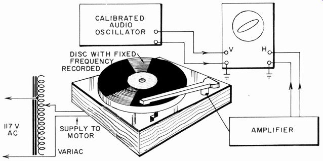
Fig. 802. The scope can be used to make a more precise determination of speed.
With synchronous motors, changes in supply voltage does not produce speed variations. However, changes in frequency will affect speed. With induction motors, however, changes in frequency or voltage are liable to produce changes in speed.
For precision control, the only satisfactory way seems to be to use an electronic frequency source that is independent of supply variations. For practical purposes, a synchronous drive from a line source of 60 cycles provides a satisfactory speed control on the long-term variation. The frequency of the line supply cannot change very abruptly, because one virtually has to vary the inertia of the generators at the power house to produce a change in speed.
But this only refers to the long-term fluctuation. It is possible for a turntable to fluctuate back and forth by considerable phase angle from actual synchronism with the alternator rotor. Also, if a rubber idler wheel or a belt is used to transfer the drive from the motor to the turntable, there is a possibility of some slippage between the two. These variations are not likely to occur with changes in supply voltage or frequency. They come under the category of flutter and wow.
Flutter and wow
Most flutter and wow meters employ a frequency-modulation principle to detect variation in speed. Usually a 3,000-cycle note re corded on a disc is played back by a pickup on the turntable and fed to the flutter and wow meter. This feeds the 3,000-cycle tone to an FM detector tuned to 3,000 cycles, with a very critical ratio-detector or discriminator designed to indicate fluctuations of the order of 1 cycle. The output from this detector is then amplified as an audio frequency and indicated in magnitude as percent deviation of flutter or wow. This arrangement is illustrated in Fig 803.

Fig. 803. Basic arrangement of flutter and wow meter.

Fig. 804. Different curves for the relative sensitivity of the human hearing
faculty to flutter speed deviation: Curve 1: According to Schecter, single
tone of 1000 cps. Curve 2: According to Alberscheim & MacKenzie, 500 cps.
Curve 3: According to Alberscheim & MacKenzie, 1000 cps. Curve 4: According
to Alberscheim & Mac Kenzie, 3000 cps. Curve 5: According to Alberscheim & MacKenzie,
7000 cps. The difference in level could also be due to the use of a different
loudness level in the test.
The effect of flutter or wow on reproduced music depends to some extent upon the frequency at which the speed deviates and the kind of program its deviation modulates. Instruments with constant, almost perfect, intonation, such as the piano, make this kind of deviation much more noticeable than instruments that normally have some tremolo or vibrato effect.

Fig. 805. Frequency. response of weighting network used in a meter developed
by the Material Laboratory, New York Naval Ship yard.
The most noticeable frequency is in the region of 2 to 3 cycles.
A cyclic change in speed at a slower or faster rate than this tends to be less noticeable (Fig. 804). Making the measurement with a weighting network that causes the indication to be modified according to the annoyance value of the frequency at which it occurs seems a good idea (Fig. 805). The problem is in finding an agreed weighting characteristic that will be accepted as a standard, and the avoiding of possible ambiguity until the new standard is fully accepted in place of the straight measurement.
This problem, both in relation to measuring flutter and wow and in noise measurement (particularly hum), has, to date, pre vented an effective transfer to a subjective type of standard. Most measurements are given in straight percentage or db, without frequency discrimination.
When measuring speed constancy, flutter and wow, turntable loading must be considered. With most modern pickups having a stylus force of not more than 5 or 6 grams (in many instances as low as 1 or 2 grams), the loading due to the pickup is extremely low and unlikely to affect speed. With earlier pickups, placing the stylus in the groove of the record would slow the turntable by a visible amount. However, when measuring the characteristics of a turntable, just how much loading the turntable will stand before it begins to show signs of serious speed deviation or flutter and wow must be determined.

Fig. 806. Speed/torque measurements show the difference in motor performance.
Curve A, a hysteresis synchronous motor with very constant speed. Curve B,
an induction motor with high stalling torque, but poor practical performance.
Some prefer to specify the pullout torque--the point at which the loading causes the turntable to come to a standstill-either by stopping the motor or causing the drive to slip. But for practical purposes the pullout torque is far less important than the effect of lesser degrees of loading on the speed constancy.
Considerable force may have to he used to stall a motor and yet it can develop quite an appreciable amount of flutter and wow with relatively low values of loading. On the other hand, another motor may require considerably less force to stop it altogether and yet give quite satisfactory performance with the same amount of loading likely to be achieved by the stylus of a pickup (Fig. 806).
An example of this difference was encountered in some checks using a turntable to drive a simple tape recording device designed to fit over the turntable. When this was tested in conjunction with a turntable that gave practically the lowest value of flutter or wow in the industry, a very large amount of flutter and wow was noticed on the tape. It was due to the tape drive mechanism imposing considerably larger loading on the turntable than it was designed for.
Rumble
Rumble is a form of spurious vibration generated by the motor and transmitted to the turntable. It can produce an output in the pickup. It can be measured by using a disc with an unmodulated groove so that any vibration transferred through the turntable and the disc to the stylus will produce an output which can be analyzed (Fig. 807).

Fig. 807. Setup for testing for rumble.
While one of the troublesome rumble frequencies is in the region of 30 cycles-and this can cause considerable trouble if there is an arm resonance in this region-bad cases of rumble can also occur at higher frequencies, such as 120 or even 180 cycles.
These then give an impression very similar to electrical hum. The difference is that the hum appears only as the stylus touches the unmodulated groove of the record.
Vertical, as well as lateral, vibration must be checked. This requires a vertical type pickup, one designed for playing vertical or hill-and-dale recordings. With the advent of the stereo disc, it is even more important to check that turntable drives are as free of rumble vertically as laterally.
There are two possible approaches to minimizing flutter, wow and rumble from turntable drives. Measurement techniques may need to be applied to the determination of effectiveness of work in this area and to investigation of possible design approaches.
The approach in the great majority of designs to date uses what is virtually a mechanical filter to reduce fluctuations and vibration produced by the motor to an absolute minimum in transferring the motion to the turntable. The motor itself must have a mini mum of these undesirable qualities to start with. But it has been generally conceded that it is impossible to get a motor good enough without further filtering in the drive.
Careful attention to dynamic balance in the motor and to absolute freedom of friction, eccentricity or lateral "slop" is essential as a starting point to a good design. Some axial motion in the motor shaft is sometimes advantageous in achieving freedom from the development of uneven friction as the components wear.
Having selected the best possible motor, the next step is to use a mechanical filter, of which the most popular are the belt and the idler wheel. The resilience of this intermediate link, in conjunction with the mass or inertia of the turntable, serves as a mechanical filter to attenuate residual speed fluctuations in the form of flutter and vibration that would cause rumble.

Fig. 808. Points to check with vibration pickup are indicated by arrows.

Fig. 809. The standard setup for measuring sensitivity to a hum field.
The use of vibration pickups with a frequency analyzer can prove useful here in measuring the vibration at each point in the system, so the effectiveness of the mechanical filter can be checked.
It may also serve to locate sources of stray coupling that may "bypass" the filter action (Fig. 808). Mechanical filtering action is required, not only for the drive, but for the motor mounting, so the vibration will not travel through the motorboard instead of the drive.
Hum
Hum radiation is rather difficult to tie down in terms of measurement. It is not picked up mechanically but electrically or magnetically, due to the stray field from the turntable motor. It depends on the position in which the pickup is mounted and also on the susceptibility of the pickup to electrical or magnetic pickup.
In general, crystal or ceramic pickups are insensitive to any form of magnetic hum, while magnetic and moving-coil types are insensitive to electrical hum. Many pickups are deliberately de signed to avoid hum pickup, but often this works only provided the magnetic field is of sufficiently low order. If the pickup is placed close to a fairly intense magnetic field, the hum-balancing device can be saturated and still produce an induced hum.
The only standardized form of hum field is not really representative of the effects produced in practice. The standard method of measuring sensitivity to hum pickup is by placing the pickup (or other device) at the center of a coil 1 foot square of a known number of turns and passing a known alternating current through the coil (Fig. 809). This produces a calibrated magnitude of magnetic field at the center of the coil.

Fig. 810. This illustration indicates why a measurement with the setup of
Fig. 809 may not be valid for practical application.
Such a test fixture produces a conveniently symmetrical and linear form of field. The output from a device placed in this position may well be perfectly balanced due to an a static or hum-balancing construction. But the same device is not equally efficient in rejecting nonlinear asymmetrical hum.
About the only place where such an academically balanced and symmetrical field would be encountered in an electric motor is right inside the motor. Outside, the field is always divergent, spreading out away from the motor. Consequently, measurements taken with a calibrated coil of this type are not always indicative of the effect of a practical hum field (Fig. 810).

Fig. 811. A direct method of measuring field radiation from a motor.
This means that it is impossible to give absolute figures for the sensitivity of any particular type of pickup to hum field.
Similarly, since the pickup cannot be given a calibrated sensitivity value, it is not plausible to give a radiation value to the motor. True, the magnitude of hum field can be measured by a suitable search coil of known dimensions placed crosswise on the field by rotating it to find a maximum, and then measuring the output from the coil through an amplifier.
Using this method (Fig. 811), figures can be given to the hum field radiated from the motor in different directions. Thus comparisons can be made between one turntable and another.
Most measurements and tests performed on record changers do not strictly come within the purview of audio-or even electrical measurements. They come more under the heading of reliability and endurance testing-finding out how consistently the arm "finds" the start groove of records of different sizes and how well the operation maintains different aspects of its mechanical performance. These are quite complicated and sometimes difficult things to evaluate.
From the audio point of view there are effects that a record changer produces which require measuring or evaluating. For example, immediately after the changer mechanism has operated and the stylus first descends into the groove of a new disc, there may be speed fluctuations that do not occur normally during the steady running of the turntable. The normal type of flutter and wow meter is used to check this. Another possibility which is not strictly dependent upon the mechanism itself is slippage between discs. This depends largely on the stylus force and how much drag it produces on the top disc.
Another important thing in record-changer performance is whether the mechanism interferes in any way with the normal freedom of arm movement. This must be checked to see that there is no drag that may produce a side stress on the pickup. It is particularly important for changers that are intended to be used with modern high-compliance pickups.

Fig. 812. Measuring the drag produced by a tone arm.
The effect of drag is tested with any pickup, using an A-N test record to see how side stress increases the IM compared to playing the same pickup in a simple arm on a turntable. But the effect varies with drag and pickup types.
To measure drag only requires the use of quite delicate force-measuring equipment (Fig. 812) to measure static friction which resists the commencement of movement or dynamic friction that occurs while the arm is moving. The latter requires more elaborate equipment and fortunately the former measurement gives the in formation most important to arm operation-unless viscous damping is used.
Associated with this "handling" aspect is the possible damage to the beginning of the record due to a too sudden lowering of the stylus into the groove. Again this feature is not something one can give figures to. There is no definite figure of safe rate at [… missing content ]