Multi-speaker systems have much to offer for good high fidelity reproduction, in the way of characteristics that are virtually impossible to obtain from a single wide range speaker. Advantages derived from the multi-speaker system are due to the fact that with two, three, or four speakers in the reproducing system, we have better control of the overall performance characteristic of the system through control of the individual component speakers. The situation may be likened to the difference between having only one ceiling lighting fixture in a room to provide overall illumination, and using several lamps in corners and on tables to provide more adequate light coverage in specific areas where light is most needed and in degrees best suited to those areas.
Special Purpose High Efficiency Components Conserve Audio Power
One important point concerning multi-speaker systems, which we have already covered in the treatment of the specialized speaker, is the greater degree of efficiency that may be obtained from a special purpose speaker. Since multi-speaker systems are composed of combinations of these special purpose speakers, the multi-speaker system as a whole is a very efficient system.
-------------
10 WATT AMPLIFIER
AMPLIFIER SET TO DELIVER 5 WATTS OUTPUT FOR AVERAGE INPUT SIGNAL WILL NOT REPRODUCE POWER PEAKS OF 20 WATTS 10 WATT AMPLIFIER WHEN AMPLIFIER GAIN IS REDUCED TO DELIVER ONLY 2 1 / 2 WATTS ON AVERAGE INPUT SIGNAL, THEN SUDDEN BURST OF POWER OF 10 WATTS WILL BE DELIVERED DISTORTED
10 WATTS 5 WATTS LOW EFF. SPEAKER WITHOUT SEVERE DISTORTION, AND LOUDSPEAKER WILL REPRODUCE THIS TONE BURST WITH EQUAL DISTORTION UNDISTORTED 10 WATTS
2 1/2 WATTS \A, HIGH EFF SPEAKER DISTORTED PEAKS
SAME POWER OUTPUT UND STORTED PEAKS CLEAN TO LOUDSPEAKER, AND THE LOUDSPEAKER WILL REPRODUCE THE SAME AVER AGE ACOUSTIC POWER AS IN FIRST CASE, BUT WITH CLEAN PEAKS AS WELL
-----------------

Fig. 6-1. A low efficiency speaker requires a high amplifier gain setting
producing distortion on peaks. A high efficiency speaker permits low
amplifier gain setting resulting in less overdriving of amplifier on
peaks.
---------------
But just what does efficiency mean in this case? Primarily, it means greater utilization of the electrical power in transforming it into sound. It means more conservative use of available amplifier audio power, resulting in more adequate reserve in the driving amplifier to take care of sudden bursts of signal. This point should be clearly under stood, for it may make the difference between good listening and poor listening. Consider the case of a system with only one low efficiency speaker as a reproducer connected to a 10-watt amplifier. Speaking broadly, 10 audio watts is more than enough to fill the average listening room. In fact, only a small portion of this available power is actually used under normal conditions. The actual setting of the volume control, however, depends upon how loudly one wants to hear the music. The ultimate loudness that the ear hears, however, depends upon more than the amplifier capabilities. If the speaker used is low in efficiency due perhaps to small magnet weight, the sound reproduction may be too low in power, making it necessary to turn up the amplifier volume control. If the room is full of overstuffed furniture and drapes, the high frequencies will be absorbed and the listener will probably compensate for this condition at the amplifier by boosting the treble gain control.
Thus, despite the fact that it doesn't take many acoustic watts for comfortable listening, the overall listening conditions, plus the speaker sensitivity, may dictate rather more than moderate audio wattages to be fed to the loudspeaker.
Let us, for the sake of discussion, say that the volume control of the 10-watt amplifier has been turned up so that 5 watts of audio power are fed to the single low efficiency speaker system for a given set of listening conditions, and that the music is playing at an even level.
Suddenly there is a burst of signal voltage into the amplifier. Perhaps the cymbals of the orchestra have clashed loudly, or maybe the trumpets have blared forth with a loud fanfare. Or suppose the whole orchestra has erupted into sudden fortissimo chords. This sudden signal voltage may in its peak value be four or more times higher than the average signal level before the sudden and momentary onslaught of power.
What happens to the amplifier? Having been originally set to deliver 5 watts of audio power, it is now overdriven far beyond its rated power; its output will be severely distorted. The natural consequence is that the speaker will reproduce distorted sound on this momentary high burst of power. (See Fig. 6-1.) Now let us change the conditions and replace the low efficiency speaker with a much more efficient speaker. What shall we consider a much more efficient speaker? We shall be conservative, and apply the common rule of thumb. If you can just barely detect a difference in the general loudness of the sound, the output from the more efficient speaker is 3 db higher. In actual power measurement, this 3 db represents twice as much acoustic power developed. If we now turn down the volume control of this 10-watt amplifier (which was previously delivering 5 watts) to deliver 2 1 / 2 watts (half its previous power), we get the same sound output from the high efficiency speaker that we previously obtained with the low efficiency speaker for the 5-watt setting.
Now, with this reduced gain setting, let a sudden tone burst of four times the average power be applied to the amplifier. It will be driven just about to its peak power (2 1 / 2 X 4 = 10) and its output distortion under these conditions will be far less than when it is more than 100 percent overdriven, as it was in the first case.
Note that this comparison was made between two loudspeakers in which one could barely hear the difference in sensitivity. It is obvious that an amplifier feeding an exceptionally efficient speaker could operate at a tiny fraction of its rated output, with virtually no danger of being overdriven on even the most severe peaks.
Reserve Power Handling Capacity Necessary for High Program Bursts
Thus we see that no part of the electro-acoustic circuit may stand alone. All parts must be considered as one integrated system. It is interesting to note that there are on the market many hi-fi amplifiers intended for the home that have power ratings of 20 to 50 watts. When used with high efficiency systems, the actual average power drawn from these amplifiers for home consumption is in the order of only 2 to 3 watts or less. The reserve power of as much as twenty-five times the average lies in reserve for those sudden impulses and bursts so that they may be transferred to the loudspeaker with a minimum of distortion. However, these benefits of reserve power in the amplifier may not be reaped without the aid of such high efficiency loudspeakers as the woofer, midrange, and tweeter units designed for multi-speaker systems.
Multi-Speaker System Reduces Intermodulation Distortion
In addition to their ability to conserve valuable audio power, multi speaker systems also give cleaner reproduction than single speaker systems. There is less intermodulation distortion in a multi-speaker system. This type of distortion occurs when a single vibrating diaphragm tries to reproduce a high frequency note while straining itself to the limit to reproduce a low note. Any irregularity of performance of the diaphragm in reproducing the low note will be imparted to the high note, because the high note, in a sense rides "piggy-back" on the low note, as shown in Fig. 6-2. The high note is thus modulated by
WHEN A DIAPHRAGM MOVING NONLINEARLY AS INDICATED BY THE "FLAT TOP" REGIONS OF THIS SIGNAL HAS SUPER IMPOSED ON ITS MOTION A VERY RAPID VIBRATION OF SMALL AMPLITUDE, THEN THE SLOWER VIBRATION CARRIES ALONG THE SMALLER FASTER VIBRATION IN THE FLAT TOP AREA, THE SMALLER VIBRATION WILL SIMILARLY BE FLATTENED OUT LEAVING EFFECTIVELY
"MODULATED" HIGH FREQUENCY SIGNAL CENTER AXIS THE HIGH FREQUENCY SIGNAL "MODULATED" BY THE NON LINEAR MOTION OF THE LARGE LOW FREQUENCY SIGNAL

Fig. 6-2. Intermodulation distortion may occur where high frequencies
are carried by a low frequency diaphragm into regions of non-linearity
of motion.
the low note. If, however, the high note has its own private loudspeaker, it becomes completely free, mechanically, of any low frequency effects, and come what may out of the woofer, the tweeter sounds clean; that is, there is no intermodulation between the lows and the highs. Obviously, then, the more separate speakers there are in a system, each with its own restricted range, the cleaner will be the overall sound.
Multi-Unit Speakers May be Balanced Against Each Other
There is one more general advantage to the multi-speaker system, and that is the ease with which the acoustical picture may be balanced to suit the ear of the individual. Speakers may be balanced, one against the other, by means of volume controls to give that particular feeling of concert hall reality that most pleases the listener. The "presence" of the midrange speaker and the brilliance of the tweeter may be readily adjusted to one's own particular musical taste.

Fig. 6-3. For maximum smoothness of response, speakers should be matched
in efficiency.
Speakers Must be Matched in Efficiency
The discussion thus far has been concerned with the benefits that may be obtained in listening pleasure from multi-speaker systems.
There are, however, prerequisites that must be met by the components of the multi-speaker system in order to produce these advantages. The speakers must all be matched in efficiency so that a smooth overall response may be obtained, without holes or bands of silence in the audible spectrum. Thus, for instance, if a high efficiency 15-inch woofer were to be installed in a folded horn enclosure (which would further raise its operating efficiency), it would be necessary to balance these heavy lows with a tweeter equivalently high in efficiency (for example, a compression type horn loaded system, such as that illustrated in Fig. 6-3). A small cone type tweeter of the direct radiator type would be completely lost in listening perspective. There would be a complete absence of brilliance and life in the music. On the other hand, a cone type tweeter may be a perfectly good adjunct to a 12-inch moderate efficiency woofer when the latter is used in a bass-reflex enclosure. If the system is a three-way reproducer, all three units should be matched in efficiency so that the listener may have a flat system to adjust in accord with his individual preferences.
Speaker Ranges Must Overlap
Not only must the speakers of a multi-speaker system be matched in efficiency; they must also have compatible "roll-off" or "cutoff" characteristics; if they don't there will be holes in the response curve.
Every loudspeaker, no matter how well designed, has limits to its performance. It has a low frequency limit, below which it loses output rapidly, and it has a high frequency limit, above which output also falls rapidly. The more specialized the loudspeaker the narrower the range within which it works, and consequently, the closer in frequency are the low frequency cutoff and high frequency roll-off points. We must be careful, in choosing the components of multi-speaker system, that one speaker's response doesn't fall short of meeting that of the other speaker. Thus, as illustrated in Fig. 6-4, if the woofer horn circuit response fell off rapidly above 500 hz, we could not employ a midrange speaker that started to operate at 1000 hz. If we did there would be a whole octave of depressed response between 500 and 1000 hz. On the other hand, a minimum overlapping of the areas of operation of the components of a multi-speaker system is necessary for smooth response, although more extensive overlapping may be permissible under certain conditions. There is, of course, no hole in the response where such overlapping exists; thus smoothness is maintained.
However, other effects not necessarily either desirable or undesirable enter the picture. If the overlapping area of response between the two speakers is very great, the audio power in this region is divided between the two speakers in equal proportions. If both speakers are equally efficient in this common overlapping area, and further, if each speaker is able to handle the additional power at frequencies that may be slightly outside its normal operating range, perhaps nothing has been lost, except that some degree of intermodulation may have crept in due to the increased bandwidth now covered by the overlapping speakers. However, if the overlapping area is not desired, it may be ...
----------------
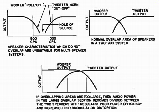
Fig. 6-4. For maximum smoothness of response, speakers should have compatible
roll-off and cutoff slopes.
WOOFER "FtOLL-OFF TWEETER HORN " CUT -OFF' 500 1000 HZ; HZ SPEAKER CHARACTERISTICS WHICH DO NOT OVERLAP ARE UNSUITABLE FOR MULTI -SPEAKER SYSTEMS. WOOFER OUTPUT WOOFER TWEETER OUTPUT; OUTPUT NORMAL OVERLAP AREA OF SPEAKERS IN A TWO-WAY SYSTEM TWEETER OUTPUT IF OVERLAPPING AREAS ARE TOO LARGE, THEN AUDIO POWER IN THE LARGE OVERLAP SECTION BECOMES DIVIDED BETWEEN THE TWO SPEAKERS WITH RESULTANT POOR POWER EFFICIENCY AND INCREASED INTERMODULATION DISTORTION
--------------------
... controlled by means of a crossover network (which should be part of every multi-speaker system).
Crossover Networks Determine Speaker Overlapping
The crossover network (section 7) functions very much like a traffic policeman, channeling the various bands of frequencies into speakers specifically designed to handle them. Between the speaker mil e characteristics and the crossover network attenuation characteristic, the response of the speakers in the overlap areas may be controlled to provide the proper degree of overlap. Too broad an overlap and too slow a roll-off may result in a lack of definiteness of response from the individual speakers. If the listener wishes clear-cut demarcation be-tween the sounds of the various speakers, short overlap and fast roll-off are prescribed. This may produce a feeling of separation of the instruments, producing an illusion of a close-up view of the orchestra. If, however, the listener desires an overall blending of sound, as if he were seated well back in the concert hall, greater overlapping and slower roll-off are required so that there will be no sharp demarcation of sound between the individual loudspeakers.
Those factors which actually determine the roll-off and cutoff characteristics of the speakers are, in general, those of enclosure and baffling conditions, and will be treated in the sectionon the baffle as a crossover element. (See Part 2.) Of immediate importance is the necessity of choosing the individual speakers so that they definitely overlap sufficiently in their respective performance ranges to be subsequently con trolled to proper advantage to provide the specific amount of overlap desired by the individual.
Speakers Must Overlap in Angular Distribution
Thus far we have discussed the necessity of matching the speakers of a multi-speaker system in terms of efficiency and compatible over lapping areas of response. In addition to these, there is a third condition of performance that speakers of a multi-speaker system must meet - that of polar response, or angular distribution of the sound, especially at the upper frequencies. This criterion applies to the overlapping area of the midrange speaker and the tweeter of a three-way system, or of the upper end of the woofer and tweeter of a two-way system.
Angular distribution is most likely to be a problem when a cone type speaker is used, as is often the case for the midrange unit.
We have seen (section 3) that as the frequency of reproduction of a cone speaker goes up the energy becomes more tightly beamed, with the result that the overall angular performance of the cone drops off.
In order to maintain effective smoothness of response projected into all parts of the listening area without holes, it is desirable to bring into play a tweeter of the wide angle type to provide uniform angular dispersion of those frequencies at which the cone distribution begins to deteriorate. Thus, for instance, if we find that at 8000 hz the midrange cone is 10 db down in level for an angular dispersion of 45 degrees off axis, as shown in Fig. 6-5, it may be desirable to roll off the speaker output well below this frequency, say at 5000 hz (where the polar response is fairly good), and bring into play at that frequency the wide angle tweeter, which will carry the high frequency response into the angular position with far less loss than the cone.
By satisfying these three conditions of comparability for the multi speaker system (equal efficiency, overlapping frequency ranges, and compatible polar response crossover points), we obtain an overall response that is smooth both in level and in angular distribution with clean performance and a feeling of concert hall reality for the system as a whole.
---------------
RESPONSE OF CONE AT 8000 HZ is 10 DB BELOW THE "ON AXIS" RESPONSE; RESPONSE OF CONE AT _ 5000 HZ IS BROADER. IT IS DOWN ONLY 3 DB BELOW THE "ON AXIS" RESPONSE CONE SPEAKERS PRODUCE SHARPER BEAMS AS THE FREQUENCY GOES UP WHEN USED AS A MIDRANGE SPEAKER, THE CONE SHOULD BE USED ONLY UP TO THE FREQUENCY WHERE ITS BEAM BEGINS TO NARROW DOWN; IN THIS CASE ONLY UP TO 5 KC

Fig. 6-5. When used as a midrange speaker, the useful upper range of
a cone is determined by its high frequency beaming effect. At the frequency
where the beam narrows down, a wide angle tweeter should be used.
-----------
"Presence" is Determined by Middle Frequency Performance
In describing concert hall realism, a term commonly used in audio terminology is presence. This is a neat and specific word signifying a feeling that the performer is actually present in the room with the listener. This feeling is created by the middle frequencies of the re producing system, a phenomenon that may be easily demonstrated with a three-way speaker system in which the midrange speaker volume is adjustable. When a vocal selection is being played and the midrange speaker level is turned down, producing some appreciable lowering of sound from this speaker, the vocalist appears to have receded into the background, while the rest of the music remains predominantly un changed. Turn the midrange level back up a little and the performer seems to step right back into the room. The same is true of instrumental selections. 'When the middle frequencies are lowered in level, the music seems to have lost its reality, its "presence." Presence is an important quality in any single loudspeaker or multi-speaker system. It is more readily obtainable with the more efficient horn type projectors. The very fact that the midrange speaker is a real horn causes the middle frequencies to be projected right into the listener's lap. A stage full of violins, for instance, doesn't have nearly the sound projecting power as a handful of trumpets and trombones.
However, as we explained in the opening chapters, high fidelity is a personal thing governed by one's own personal makeup. There is nothing essentially right or wrong about strong presence in music. If one likes a more remote effect, the cone speaker will provide the proper middle. It must, of course, be realized that this remoteness will be the result of the comparatively low efficiency of the cone speaker as compared to a horn system. There will also be a more subtle difference than that of efficiency. There may be a difference in quality as well.
There are those who like horn sounds, and there are those who like cone sounds. If we could provide a set of horn reproducers to play back only the music originally produced by the actual horn type instruments, and cone type reproducers to play back only the music of instruments whose sound is produced by vibrating panels (like the violins), perhaps we would have better fidelity. However, we have to choose one type or the other to play back sounds of both horn and membrane instruments. The choice is specifically a personal one, but the source of presence is indisputable. The middle frequencies have it.
When they are reduced, presence is reduced. When they are increased, presence is increased.
Multi-Speaker Systems may Grow from Single Wide Range Speaker
Although it is true that multi-speaker systems are made up of special purpose speakers, it is nevertheless possible to develop a multi- speaker system from a single wide range speaker, adding other components as means permit, or as one becomes more familiar with the art. Hence it is possible for the beginner in high fidelity to start out on a modest basis with a single speaker and enjoy it without feeling for ever bound to that system, or fearing its obsolescence should he want a more extensive system. Recently there has been a trend to the "progressive speaker expansion" system, which permits the hi-fi fan full enjoyment of that initial choice until he is ready to add further components. It enables him to grow in the art in stages and learn exactly what he wants out of his high fidelity system. We are now in a position to discuss examples of such systems, having already covered the elements of multi-speaker systems.
Added Tweeter Gives Improved and Better Controlled High Frequencies
As an example, let us assume that one's finances have dictated that he start his adventures in hi-fi with a single 12-inch wide range speaker, such as the one shown in Fig. 6-6. Although this speaker by itself may give commendable performance, we know from our listening experience that there are certain limitations in its performance. Perhaps the most fertile area of improvement in a reasonably good 12-inch cone is the extension of high frequency response and of high frequency angular distribution. In order to accomplish the improvement in these directions, we obviously must look to the use of a tweeter. Therefore, to the already existing wide range speaker, we now add a wide angle compression driver horn loaded tweeter that will accomplish both of these objectives. More high frequencies will now be available in the region in which the cone speaker was beginning to roll off; and these newly added high frequencies will be dispersed more uniformly through out the room.
--------------------
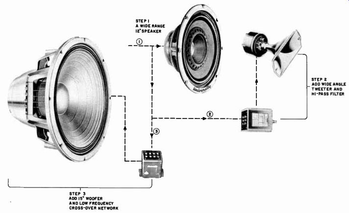
Fig. 6-6. A typical progressive speaker expansion system starting from
one basic wide range speaker, expanding first the treble end and then
the bass end. ( Courtesy University)
STEP I A WIDE RANGE I2 SPEAKER CD STEP 3 ADD IS" WOOFER AND LOW FREQUENCY CROSS -OVER NETWORK STEP 2 ADD WIDE ANGLE
- TWEETER AND NI -PASS FILTER
----------
COAXIAL ASSEMBLY WITH RECIPROCATING FLARE TWEETER HORN, BUILT-IN NETWORK, AND CONTINU OUSLY ADJUSTABLE TWEETER CONTROL WOOFER -W" MAGNET TWEETER NETWORK ADJUSTABLE TWEETER CONTROL WooFER CONE TWEETER CONE (A) COAXIAL ASSEMBLY WITH MODIFIED MULTICELLULAR TWEETER HORN, AND EXTER NAL NETWORK WITH TAP ADJUSTMENT FOR TWEETER VOLUME CONTROL WOOFER RING MAGNET WOOFER CONE TWEETER HORN TWEETER UNIT NETWORK AND TAPPED TWEETER CONTROL (B)

Fig. 6-7. Two typical 12-inch coaxial speakers showing construction,
net work placement, means of tweeter level control. ((A) Courtesy University;
(B) Courtesy Altec)
----------
The addition of such a tweeter is accomplished through the use of a network or a high-pass filter for optimum utilization of the high frequencies of audio power. By adding a tweeter to the wide range speaker, we have expanded our system in frequency, and we have literally added a new listening dimension. Albeit the original speaker may have given adequate and pleasing high frequency response, the addition of the tweeter adds a tingle and a sparkle; a new brilliance possible only with a speaker designed specifically for such reproduction.
Added Woofer Gives Improved Low Frequencies
Having now added to the high range and spread of our system, we may stop there for a while, and enjoy the improved performance for weeks or months. The time may come, however, when awareness of the improvement in the high frequency performance of the system fosters a desire for low frequency improvement. Knowing that better low frequencies may be obtained with a 15-inch woofer speaker, it becomes a simple matter to provide a broader base (or bass, if you prefer) for the original system by the addition of such a specialized low frequency speaker as that shown in Fig. 6-6. Again it is desirable that a network be used between the new adjunct and the original speaker to provide the necessary frequency separation between the two.
Original Wide Range Speaker Now Becomes Improved Midrange Unit
In fact, with networks tied to both sides of the original speaker (one at the high end, relieving it of the high frequencies, and one at the low end, relieving it of the low frequencies), the original wide range speaker has now become a specialized midrange speaker. It now reproduces only a restricted middle band of frequencies and does so more cleanly than if it were carrying the whole spectrum. Furthermore, by being relieved of the necessity of reproducing the low frequency range, the speaker may be put into a much smaller enclosure. This smaller midrange enclosure will boost the middle range efficiency of the original general purpose wide range speaker above what it was when matched to the large enclosure. The smaller midrange enclosure acts as an acoustic stiffener to the speaker, raising its resonance frequency and giving it increased efficiency in the middle range. Once again, by restricting its range, we have added more specialization to a speaker, and as a consequence we have obtained better performance within that range. Now we have progressively expanded our system from a single wide range speaker system to a multi-speaker system of specialized components without obsolescence of the original equipment.
Coaxial and Triaxial Speakers are "Packaged" Multi-Speaker Systems
Up to this point we have been treating the matter of multi-speaker systems from the standpoint of separate components. Multi-speaker systems may of course be packaged, or integrated into a single structure, as in a coaxial or a triaxial speaker. There are advantages and disadvantages to both systems; we shall deal with these in due time. Essentially, the coaxial and triaxial multi-speaker units are a combination of specialized speakers, all integrated into one design by the manufacturer of the loudspeaker. If the speaker is a coaxial unit, it has two units, a woofer and a tweeter. If the speaker is a triaxial unit, it has a woofer, a midrange section, and a tweeter. Figure 6-7 shows two typical 12-inch coaxial speakers, with cross-sectional views of both.
These structures have their own matched networks to provide the necessary frequency separation between the sections. In one, it is pack aged directly with the assembly and there is a continuously adjustable tweeter level control. In the other the network is mounted externally, and tweeter volume is adjusted by choosing the proper tap on the net work. Thus the manufacturer of each of these two packaged speakers has integrated the components in the manner he deems to give the best balance, for the particular size and price of the speaker.
Multi-unit Speakers are Systems "Balanced" by the Manufacturer
In Fig. 6-8 are shown two triaxial assemblies. In one structure there is a 15-inch woofer section, a midrange diffusion section coupled to the woofer and using the mechanical crossover principles described in section 3, and a tweeter concentrically arranged through the woofer and midrange sections. The other consists of a woofer, a separate midrange speaker, also concentrically mounted with the woofer, and a tweeter unit mounted at the front, off center, so as not to impede the sound issuing from the mouth of the midrange horn. In both structures the manufacturer has provided specifically coordinated three-way systems in which the components and the integrated crossover network are matched to each other in efficiency, in overlapping frequency areas, and in angular distribution. These three factors have been integrated by the manufacturer to provide what appears to him to be the optimum in listening balance, smoothness, and cleanness of response.
However, it is recognized that, despite the fact that the manufacturer has built into his system the ultimate in listening performance as he sees it, the listener should be provided with a means of adjusting the speaker system to suit his particular needs and desires. Therefore, controls have been added to the upper frequency portions. It is seldom that the bass end needs any compensation. The actual fact is that we always seem to want all the bass we can get out of a speaker system, and we adjust the treble to match. Volume controls are usually provided as integral parts of the whole assembly of the coaxial or triaxial units to allow the listener to strike his own balance between the highs and the lows.
----------------------
15" TRIAXIAL WITH MIDRANGE DIFFUSER SECTION, WIDE ANGLE CONCENTRIC TWEETER, AND INTEGRAL NETWORK WOOFER MAGNET TWEETER DRIVER NETWORK (A) WOOFER CONE WIDE ANGLE TWEETER HORN MID RANGE DIFFUSER WITH MECHANICAL CROSSOVER 15" TRIAXIAL WITH CONCEN TRIC MIDRANGE DRIVER AND HORN, EXTERNAL TWEETER AND NETWORK WOOFER MAGNET MID RANGE DRIVER MID RANGE HORN (8)
TWEETER DRIVER WOOFER CONE

Fig. 6-8. Two typical 15-inch triaxial speakers showing construction and network
placement. f(A) Courtesy University; (B) Courtesy Jensen)
------------------
Tweeter "Brilliance" Control Affects Level, Not Range, of High Frequencies
It is interesting to note that these tweeter controls do not function as do the treble controls on an amplifier. The tweeter control does not roll-off the high frequencies progressively as it is turned down; it maintains the entire plateau of the frequency range of the tweeter, but subdues the overall level of this plateau, as indicated in Fig. 6-9. Thus we still maintain full frequency coverage but balance the overall level of the various parts of the spectrum.

Fig. 6-9. Volume controls of tweeters are usually arranged to raise
or lower the entire band of response, thus keeping the tweeter frequency
band unchanged but simply altered in level. This retains full fidelity
coverage at any level of operation.
Packaged System Has Compatible Units, and Needs Direct Radiator Enclosure
Obviously, the complete packaged speaker system leaves nothing to chance as far as the ultimate user is concerned. The system is completely engineered as far as compatibility of the components goes. These components are matched in all their important parameters. All the user has to do is to connect two wires between the packaged speaker and the amplifier. For the man who wants a complete integrally engineered and packaged multi-speaker assembly, the coaxial or triaxial speaker is the answer. In addition, simplicity of enclosure design lends itself to speakers of this type. Due to the fact that these integrated assemblies contain their treble reproducers on their front faces, it is absolutely necessary that this type of speaker be mounted in a type of enclosure that permits full unobstructed front radiation from the speaker at all times, so that the high frequencies will flow out directly into the room unobstructed. For this type of radiator, the convenient and efficient bass-reflex cabinet and all its variations make very compatible enclosures. The bass-reflex enclosure affords good balanced bass response, and permits direct forward radiation from the speakers. The bass-reflex enclosure is easy to build and relatively inexpensive to buy.
The combination of an engineered package and simplicity of operation makes life easy for the man who wants balanced listening with a minimum of "do-it-yourself."
Multi-Speaker Systems Are Flexible
Although it is not as simple in construction or in choice of components, the separate multi-speaker system has its own definite and specific advantages. A major advantage, of course, stems from the fact that the system may be built progressively from small beginnings. More important, however, the units may be selected on a personal basis.
The system may be engineered or put together in ways that will afford the hobbyist the widest opportunity to play with the various components until he has nurtured the system to the conditions in which he thinks it sounds best. Such matters as choice of crossover points, attenuation rates of networks, and physical placement or displacement of speakers for different acoustic perspectives make the high fidelity field what it is.
Fortunately, the constructor of a multi-speaker system need not be entirely on his own in selecting the proper components. Many manufacturers have selected combinations of speakers as components for a multi-speaker system on the three, point compatibility system (efficiency, overlapped area, and angular spread). The systems shown in Figs. 6-10, 6-11, and 6-12 are considered by their manufacturers to be balanced and compatible three-way systems.
Comparative Packaged Systems

Fig. 6-10. A three-way multi-speaker system comprising components selected
by the manufacturer on the basis of compatible efficiencies, over lapping
areas, and angular dispersion, with matched network. System uses wide angle
reciprocating flare horns and crossovers at 350 and 5000 hz.
( Courtesy University) -------- HORNS ARE OF THE WIDE ANGLE RECIPROCATING FLARE DESIGN. -------- MODEL N-3 NETWORK WITH MIDRANGE AND TWEETER VOLUME CONTROLS
It is of interest to note the approaches of different manufacturers to system design. In the University system, shown in Fig. 6-10, the components responsible for the middle and high frequency ranges are members of the family of horns, which give wide angle dispersion through the principles of their reciprocating flares. In the Electro-Voice system (Fig. 6-11) horizontal dispersion is accomplished through the diffraction type horn. Figure 6-12 shows a Jensen system in which the middle frequency band is dispersed by a horizontally flared horn and the high frequencies are permitted to radiate in all directions by the symmetry of the high frequency horn. In the University system the cross over points are at 350 hz and 5000 hz, in the Electro-Voice system they are at 800 hz and 3500 hz, and in the Jensen system they are at 600 hz and 4000 hz. In all these systems, crossover points were chosen to be compatible with the cutoff characteristics of the horns.
In choosing components such as these, which have been engineered by the manufacturers to be the equivalent of a package, the home constructor is faced only with the choice of the enclosure; the fact that the units are separate components gives the listener a rather wide choice. He may use a bass-reflex enclosure, and employ direct radiation from the woofer, or he may use a horn system to load down the woofer. As far as the midrange speaker and the tweeter are concerned, they require no baffling, because they are horn loaded. They may be mounted on any convenient panel such as the front baffle board of the bass-reflex enclosure, or they may be boxed in a simple open-front en closure covered by a grill cloth to be mounted directly on top of the bass enclosure. They may be hung in the mouth of the low frequency horn if a horn loaded woofer is used.
Separate Speakers Provide Acoustic Breadth of Sound
Some measure of increased acoustic perspective may be obtained by actually separating the three speakers from each other by two or three feet, either within the same enclosure or in adjacent equipment cabinets. The physical separation of the speakers, added to the frequency response distribution between the speakers, provides greater apparent acoustic breadth for the reproducing system. The different sounds coming out of the expanded area of, say, 5 feet in width, become much more real than the same sounds struggling to emerge from a single hole in the baffle. If we may speak of this matter rather lightly, the physical separation of the woofer, midrange unit, and tweeter enable the reproduction of violin and trombone music with out the violinist's bow getting tangled up with the trombonist's slide.

Fig. 6-11. A three-way multi-speaker system in which compatibility of components
is accomplished by properly designed diffraction type horns, with the crossover
points falling at 800 and 3500 hz. (Courtesy Electro Voice)

Fig. 6-12. A three-way multi-speaker system using components that are
compatible for crossovers chosen by the manufacturer at 600 and 4000
hz.
(Courtesy Jensen)
Adjustable Units Aid Hobbyist in Balancing System
------------
ADJUSTABLE RESPONSE WOOFER WITH BUILT IN CROSSOVER ELEMENT ALLOWING ATTENUATION AT 700, 2000, AND 5000 HZ WOOFER 2000 TWEETER HORN WITH 2000 HZ CUTOFF WHICH WILL PERFORM WITHIN ANY OF THE CROSSOVER SECTIONS OF THE ADJUSTABLE RANGE WOOFER HIGH -PASS FILTER MODEL NI
ADJUSTABLE HIGH PASS FILTER WITH CONTINUOUSLY VARIABLE OUTPUT TWEETER N OVERLAPPING AREAS OF
\ ADJUSTABLE WOOFER RESPONSE AND TWEETER HORN CUTOFF 5000

Fig. 6-13. The adjustable response woofer plus the high-pass filter
enables the crossover between the woofer and tweeter to be chosen either
at 2000 or at 5000 hz. ( Courtesy University)
--------------
If the hobbyist wishes to make his own selection of component parts, he must be guided by the manufacturer's specifications for frequency range, angular dispersion, and efficiency. Often the hi-fi listener has a tweeter with which he is thoroughly satisfied, but to which he would like to add a new and improved woofer. He must then be sure, for instance, that the cutoff frequency of the tweeter in the low frequency overlapping area falls below the point where the woofer begins to lose output. One way of meeting this objective is to choose the woofer so that it considerably overlaps the tweeter and then to interconnect them with a network that makes available a choice of crossover points within that overlapping area. This will ensure a system having smooth transition of response between the two components at the frequency chosen by the crossover networks. Then, as shown in Fig. 6-13, there are two specialized components for multi-speaker systems, an adjustable response woofer, and a variable-crossover adjustable high-pass filter. The woofer has built into it the low-pass elements of a crossover network that inserts attenuation into the woofer circuit at the different frequencies noted, so that it may be rolled off in output at the frequency most compatible with the tweeter to be used. Now if a tweeter is chosen whose cutoff is at least as low as the lowest tap of the adjustable woofer, and if a high-pass filter is used to connect the tweeter to the woofer, the listener has a wide adjustable overlapping area of both speakers from which he may pick at will the response he prefers. If he wants good forceful middles and strong horn tones, he will crossover at about 700 hz, and let the tweeter horn reproduce these middles and trebles. If he wants subdued presence and mellow middles, he will crossover at some higher frequency such as 5000 hz, and let the cone reproduce the lows and middles and the tweeter only the trebles. Moreover, along with the high-pass filter, the level control allows the listener to balance the spectrum in efficiency, while the taps balance it in crossover. Thus we see that, because of the multiplicity of combinations of specialized speakers for multi-speaker systems, it becomes possible for the hi-fi devotee to "play" the instrument, to make tonal changes, to "voice" in much the same manner that an organist plays by setting the stops in the console and swelling the various voices. However, if the listener is of the type who would rather buy a ticket to the concert and let the experts do the playing for him, he will buy the manufacturer's complete integrated speaker system and sit back and enjoy his home "concert hall."
+++++++++++++++++