Enclosures Should Transmit, not Absorb Energy
Enclosures and baffles in general are means of transferring acoustic energy from the loudspeaker to the surrounding air. Whether the enclosure is a simple closed box or the most complex of horn structures, its main purpose is to cause the sound from the loudspeaker to be most efficiently radiated into free space so that it may be properly heard and enjoyed. Enclosures and baffles obviously do not by them selves produce any acoustic power; neither should they absorb any power, for if they do the total acoustic efficiency of the system will suffer.
Enclosure Internal Pressures are High
The key to loudspeaker enclosure construction is rigidity, or resistance to vibration. The wooden panels must be rigid so that they will not be vibrated by the sound pressures within the enclosure. If they are vibrated, acoustic work is done on them and that acoustic power is wasted.
The internal sound pressures in enclosures can be quite sizable.
Take the case of the closed box (the "infinite" baffle). It will immediately be realized that as much sound as is allowed to fill the entire room on the front side of the enclosure is also present on the inside of the enclosure, but here it is captured with no place to go. Because the sound is captured in the back, large internal sound pressures are built up, especially on low frequencies, where most of the acoustic power resides anyway. Even in the bass-reflex enclosure, in which the sound does finally come out from the port, that sound must still en counter the comparatively cramped quarters inside the enclosure be fore emerging.
These internal pressures can become quite high and may cause deleterious effects to the total acoustic performance if the enclosure is not properly constructed. It is only necessary to place one's hand on the side walls of a poorly constructed enclosure when it is reproducing a full throbbing bass note to feel the vibrations of thin or poorly braced wood panels. Practice has shown that good results may be obtained when the lumber used in the construction of the enclosure is at least 3/4 -inch thick and of a good grade of plywood or cored wood.
Back of Bass-Reflex Enclosure Must be Rigidly Made and Secured
In the case of the bass-reflex enclosure, just as much care must be shown in constructing the removable back as is given to the en closure as a whole. Too often, the constructor gives this section the minimum of attention because it is not seen. However, if it is neglected, it may not be seen but it certainly will make itself heard in undesired ways. Figure 14-1 shows the response of a bass-reflex enclosure with a properly constructed back, and again with a thin 1 / 4 -inch back held on loosely by four screws in the corners of the panel. While the sound output waveform of the enclosure with the good back is clean and undistorted, the output of the same cabinet with the poor back is rough, distorted, and lower in level than the former. The loss in output is, of course, due to the fact that much of the back radiation from the cone was used up in making the rear panel vibrate, and so was lost as far as useful acoustic output was concerned.
The waveform has deteriorated because of the irregular and comparatively uncontrolled vibrations of the rear panel, which are heard directly by the ear, and which also are reflected back internally upon the speaker to affect its initial performance.

Fig. 14-1. The back of the bass-reflex cabinet will cause waveform deterioration
and loss of level at low frequencies if it is weak and poorly mounted.
Because the back of the bass-reflex cabinet must be removable, it is often made to be held on with just one screw in each corner, as in the test just described. This is a serious mistake. Even though the rear panel itself may be of rigid stock, if it is not securely held down around its entire contact area, it will be subject to vibration. It is good practice to have at least four good sized screws along each edge of the rear panel securing it to the main structure. In the construction of the enclosure, the use of nails should be avoided as the sole means of holding the sections together. Nails will not hold them together properly for any length of time nor will the mating sections be adequately joined.
Acoustic Enclosures Deserve Fine Cabinetmaking Techniques
One should pay the same attention to the making of the acoustic enclosure as a cabinetmaker pays to the construction of a fine piece of furniture. The use of plenty of good furniture glue and screws where needed is highly recommended. The home constructor does not always have available cabinetmaker clamps to hold the sections together while the glue is setting. In this case it is advisable to make use of large screws to hold the sections together immediately after the glue has been applied to the mating edges of the panels. Not only will the screws be an aid in the construction of the cabinet, they will act as reinforcement to the finished cabinet after the glue has set, and will prevent the panels from warping away from the glued seams.
Adequate Glue Necessary for Strength and Freedom from Buzz
Adequate use of glue is more than a construction must, it is an acoustic must as well. Not only does glue provide a good mechanical bond between the sections, it also prevents buzzing of joints between those panels that are subject to high internal acoustic pressure. There is nothing as annoying as an intermittent buzz somewhere in the system that cannot be traced down. More often than not, such a buzz may occur at the areas where the panels meet, but where they are not joined together rigidly. Buzzing may be set up at these unsupported edges when the panels experience excessive internal acoustic pressures. Insurance may be taken against this sort of troublesome buzz by making certain that all these joined edges are well filled with glue before they are put under pressure. After the glue has been applied, and the sections clamped together or screwed together, there should be evidence of glue seeping out from the entire length of the joint. The surplus glue thus squeezed out should be wiped away before it hardens, to facilitate finishing of the cabinet.
It is also common practice to use glue blocks on the interior of the cabinet to add further rigidity to the entire structure and to rein force the joining edges of the panels. A typical construction illustrating the use of the glue block is shown in Fig. 14-2.
GLUE SURFACES
Where it is desired to keep the rear panel of the bass-reflex cabinet removable (or for that matter any section of an enclosure, such as the compression chamber of a horn in which the driver unit must be inserted), felt stripping may be applied to the edges of the panel so that when it is screwed down it seals itself and inter-panel buzzing is eliminated at the same time.
GLUE BLOCK SCREWS

Fig. 14-2. The use of glue blocks in cabinet construction insures squarely
braced surfaces, a means of screwing the panels together to hold them
while the glue is setting, and a means of construction whereby screws
do not show on the finished surfaces.
Bracing May be Necessary on Large Panels
Sometimes, even heavy panels will vibrate if they are large in size, and additional means must be employed to prevent them from being energized into vibration by the internal pressures. Such minimizing of the vibrations of large panels may be accomplished by the use of cross braces applied diagonally across the panel area. This diagonal position is the longest dimension of the panel, and so needs the most support. Often a sturdy cross-strut, reaching across from one panel to the opposite one, may be sufficient to break up the vibrating condition of large panels.
Speaker Mounting Panel Should be Very Flat
Of great mechanical importance to the performance of the baffle is the sturdiness and the flatness of the speaker mounting panel itself.
It goes without saying that the panel that is most subject to vibration is the one on which the vibrating loudspeaker itself is mounted. This front panel should, therefore, be chosen as the sturdiest one of the lot. If possible, it should even be thicker than the other panels, even though this may mean paying a slight premium for one piece of wood from the local lumber yard.
Of equal importance is the flatness of the panel in the area in which the speaker is mounted. A warped section of panel in this area will prevent the proper seating of the loudspeaker in its appointed place, creating two undesirable effects. First, it may be impossible to screw the speaker down fiat to a warped baffle. If the speaker has a hard un-pliable rim gasket, or simply has a hard cast ring on its mounting rim to give the speaker structural rigidity, there will be gaps be tween the speaker and the panel to which it is mounted. An acoustic leak will therefore exist between the back of the speaker and the front, which, if large enough, may cause some deterioration of the low frequency response in the bass-reflex enclosure. More important, how ever, if such a leak occurs in the compression chamber of a horn system, the action of the horn may be quite seriously upset. It is for these reasons of adaptability to baffle panels that are not completely flat, that many of today's speakers are designed with comparatively soft edge gaskets, made of a cork composition or laminated news-board. When a speaker with such an edge-sealing gasket is used, the mounting panel irregularities are somewhat taken up by the "give" in the gasket.
Sometimes actual damage may be done to a loudspeaker if the mounting baffle is too badly warped. In the effort to screw down the edge of the basket at all points, the basket rim itself may be warped out of its normally flat condition if the basket design is not well thought out. If such warping of the basket occurs, the alignment of the entire moving system may be thrown out of its true balanced position, especially insofar as the voice coil itself is concerned. If the voice coil is thus forced into a misaligned position, it may eventually start to rub against the narrow gap faces, which will result in fuzziness of reproduction, distortion, and ultimate rupture of the coil.
Speaker Should be Securely Fastened to Mounting Panel
There is often difficulty in screwing the speaker down to the mounting panel. Tragic results sometimes occur when ordinary wood screws are used. Often the wood screw is not started correctly. It begins to tilt, and the screwdriver slips from the head of the screw and goes through the fragile paper cone of the speaker. This is especially heart-

Fig. 14-3. A means of preparing the baffle panel of an enclosure to insure
positive seating of the speaker to the baffle board.
...breaking when you have just bought the speaker and haven't even heard it woof or tweet. Such damage may be prevented by drilling small holes in the spots where the wood screws are to be driven into the panel. The holes should be small enough so that the screw does not lose its grip on the wood when driven into the hole, but on the other hand, the hole should be large enough to provide a proper guide for the screw so that it may be easily driven in.
There are better means of mounting the loudspeaker than with wood screws. If the mounting panel is readily accessible from, both sides, machine screws and bolts may be used to secure the speaker.
If, however, the construction is such that the front panel is to be directly covered with grill cloth, there is another expedient that may be used. Machine bolts may be permanently inserted into the mounting panel and held tightly in place by nuts countersunk into the wood.
This will leave the mounting bolts sticking out from the back of the mounting panel ready to accept the speaker, as shown in Fig. 14-3. A word of caution is in order, however, if the speaker is so mounted.
When placing the speaker over the bolts, be very careful not to place the speaker down in such a position that the cone itself is over one of the bolts; it might easily puncture the cone. However, with reason able care, the speaker may be slipped over the mounting bolts and then readily secured by means of lock washers and nuts.

Fig. 14-4. A preferred method for preparing the baffle panel with "T" nuts.
This method provides optimum ease and safety of the speaker installation
with positive seating of the speaker to the board.
A means of overcoming this bolt problem is available through the use of "T" nuts. These are simple and relatively inexpensive de vices readily available from a local hardware merchant or cabinetmakers' supply house. They are illustrated in Fig. 14-4. Holes are drilled where the speaker mounting bolts are to be inserted. Into these holes are forced these "T" nuts from the side of the baffle opposite to that on which the speaker is to be mounted. They seat into the tight hole drilled for them and stay in place until the speaker is to be mounted.
When ready for mounting, the speaker is placed over the holes, and bolts are then driven through the speaker rim into the "T" nut. This is perhaps the safest, easiest, and surest way of mounting the speaker to its panel without danger of going through the cone with either wood screws or protruding bolts.
Panel Vibrations Deteriorate Horn Action
In the case of the horn type of enclosure, the matter of the rigidity and resistance to vibration is of even more fundamental importance than in the simpler bass-reflex type. The reason for this is two-fold.
First, as we have seen, all the sound the diaphragm produces is squeezed into the comparatively small space in the throat of the horn. If we compare the volume at the throat of the woofer horn with the volume behind the diaphragm in the bass-reflex enclosure, we have an idea of the ratio of pressures between these two conditions. If the internal pressure in the bass-reflex enclosure is considerable, how much more intense must the sound pressure be when the equivalent of this amount of sound is compressed into the relatively small throat area of a horn.
It is, therefore, of utmost importance in horn construction that no pains be spared in making the throat section as strong, as rigid, and as resistant to vibration as possible. If there is any "give" to these panels at the throat, the horn will suffer severe acoustic losses.
Special attention must also be paid to the compression chamber, for the internal pressures built up in this small volume may also be of considerable magniture. One should make sure that the panel in this compression chamber, which is usually made removable for purposes of mounting the loudspeaker on the inside, is provided with a sealing...

Fig. 14-5. Horn action may be deteriorated by weak horn construction,
especially at the high pressure areas. WHEN WALLS OF HORN ARE WEAK,
HIGH PRESSURES, ESPECIALLY AT THE THROAT - WILL SET THE WALLS INTO VIBRATION
IN A TRANSVERSE - DIRECTION TO THE NORMAL WAVE VIBRATION, WHICH WILL
CAUSE DETERIORATION OF DESIRED WAVE TRANSMISSION DOWN THE HORN
...gasket around its rim and that it is secured to the housing with enough screws so that with the felt sealing gasket in place there will be no pressure leaks in this vital area.
The second reason for making sure that there are no sections in the horn with a tendency to vibrate is that if these critical area members do vibrate, the horn action is partially destroyed. The sound pres sure developed by the driver will be partly dissipated in setting up transverse waves across the horn through putting the panels into vibration, rather than setting up longitudinal waves down the horn where they belong. This is illustrated in Fig. 14-5.
Sound Absorbing Material Stops Internal Reflections in Bass-Reflex Enclosure
Enclosure type baffles, such as the bass-reflex, require treatment with sound absorbing material on the inside of the structure. The main purpose of this treatment is to minimize standing waves within the enclosure. These waves would cause ragged mid-frequency response and boominess in the low frequency region. Let us examine the case of the bass-reflex enclosure. As the loudspeaker diaphragm vibrates back and forth, sound waves travel out from the diaphragm in two directions, forward and backward. The forward radiation naturally goes out into free space. The rearward wave motion travels backward, hits the rear panel and is then bounced back, with the greater proportion of the reflected sound coming directly back upon the speaker diaphragm, the rest being randomly scattered throughout the enclosure, and hitting the other walls of the structure.
We are concerned first with the reflected wave motion coming back directly upon the speaker. Let us suppose that the loudspeaker is playing a note of 900 hz. This frequency corresponds to a wave length of approximately 15 inches. Now, it so happens that 15 inches is rather a common depth for an enclosure of this type, and this leads to some interesting situations. For the sake of illustration, let us assume that the loudspeaker diaphragm is flat. When the 900-hz wave leaves the back of the diaphragm, it travels across the depth of the cabinet and reaches the back panel at exactly the same time the loud speaker is ready to generate its next wave. Upon hitting the back panel, the wave motion is reflected back toward its source. In the process of being reflected from the panel, the wave motion is turned out of phase with respect to its original pulsation. Now, in its reversed phase, the reflected sound reaches the back of the diaphragm again just as the diaphragm is about ready to start its next cycle of motion. This produces interference at the diaphragm between the reflected out-of-phase wave and the new wave. The net result is that a severe dip will be introduced into the output of the speaker in this frequency region.
Similar cancellation effects would occur for those frequencies at which the distance between the speaker diaphragm and the back reflecting panel is a half wavelength, one and a half wavelengths, two wavelengths, or any even number of quarter wavelengths. When the distance is such that it is an odd number of quarter wavelengths of the sound being radiated, reinforcement takes place and an acoustic peak occurs.
However, the diaphragm of the speaker is not flat. The diaphragm is generally of a conical shape. This means that the wavefront traveling toward the rear is not a plane wave, but is somewhat spherical.
All parts of this spherical wave do not hit the back panel at the same time. The forward bulging area of the wave hits first, then the other zones of the sphere make contact. Consequently, the reflected wave is sent back not in one plane but in a correspondingly varied spherical pattern, and accordingly, it reaches the back of the diaphragm over a period of time rather than all at once. In addition, the back of the diaphragm, being generally conical, presents different path lengths between its various sections and the back of the cabinet. As a result of (a) these path differences from the back of the cone to the cabinet back and (b) the spherically delayed wavefronts, the effect of the interaction of the reflected wave on the diaphragm is such as to pro duce a succession of fairly closely spaced dips and peaks in the mid frequencies, where the wavelengths are comparable to the various distances from the back of the cone to the back/of the cabinet.
In enclosures with large flat backs that do not have sound absorbent material applied to them, the mid-frequency region of response of the system suffers from these irregularities. There are, of course, re flections set up within the cabinet between the other panels of the enclosure. Because the sound glances off obliquely from one panel and then subsequently goes from panel to panel like a billiard ball bouncing from one cushion to the other, the path length, before the reflection finally comes back upon itself, may be quite large. This means that low frequencies will "roll" around the enclosure if they are not damped, and the enclosure will sound like a rain barrel. It is thus advisable to use sound absorbent material freely within the cabinet to eliminate this wall-to-wall bouncing of the sound energy.
Although it is theoretically best to treat all the panels with sound absorbent material, satisfactory results may be obtained by treating only three non-parallel sides. Such treatment will obviously do away with the major cause of repeated reflection, the bouncing back and forth of sound between the same two walls. In any event, the back of the cabinet should definitely be treated, because this panel is the worst offender as far as reflections upon the loudspeaker itself are concerned.
Next in importance is the top, because in the bass-reflex enclosure, this is usually the panel closest to the loudspeaker. Any reflection from a surface close to the source of the sound will be correspondingly more intense if the surface is not treated. After the back and top have been treated, either of the sides may be treated.
The application of sound absorbent material within the enclosure does more than minimize reflection internally. It also prevents the panels from being vibrated by the sound pressures impinging upon the panels. The sound absorbing material, being resistive in nature, reduces the intensity of the sound wave as the wave goes through it.
Corner Type Bass-Reflex Enclosure Reduces Internal Reflections
Internal reflection within the bass-reflex type of enclosure may also be minimized by the proper geometrical design of the cabinet and the vertical angle of the speaker mounting baffle. If the area of the back panel is reduced, obviously there will be less direct reflection
from the rear of the cabinet back upon the speaker. This effect may be accomplished in enclosures of the "cornerless-corner" type, as illustrated in Fig. 14-6.
This type of construction decreases the overall area of parallel surface both from back to front and from side to side, and inserts instead oblique reflection conditions. The combined effect of this structure is to reduce direct back-and-forth and side-to-side reflection, and to elongate the path of reflection, which tends to reduce the amplitude of the reflection. Fortunately, this type of cornerless-corner construction also makes the cabinet adaptable for placement either against a flat wall or in the corner of a room. This matter of placing the enclosure in the room is an important one and will be discussed in more detail in Part 3.
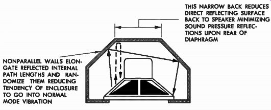
THIS NARROW BACK REDUCES DIRECT REFLECTING SURFACE BACK TO SPEAKER MINIMIZING
SOUND PRESSURE REFLEC TIONS UPON REAR OF DIAPHRAGM NONPARALLEL WALLS ELON
GATE REFLECTED INTERNAL PATH LENGTHS AND RAN DOMIZE THEM REDUCING TENDENCY
OF ENCLOSURE TO GO INTO NORMAL MODE VIBRATION
Fig. 14-6. The "cornerless corner" enclosure minimizes internal normal mode vibration and reduces reflections upon back of speaker through its non-parallel wall type of construction.
In addition to breaking up the internal reflections by this corner construction, additional reduction in front-to-back reflection may be obtained by tilting the front panel so that it faces in a direction about ten degrees above the horizontal, as shown in Fig. 14-7. This eliminates the parallel condition between the back and the front and causes oblique reflections to be set up instead, hence the rear of the speaker suffers much less from sound pressures impinging back upon it.
Horns do not Need Absorption Treatment
In the horn enclosure, the problem of sound absorption is some what different. Because of the continually expanding sections of the horn, there are seldom any parallel walls between which reflections may be set up, and therefore, sound absorbent material on the walls of the horn is not necessary. In fact, it is possible that the placement of true sound absorbing material within the horn (on the interior walls) may actually be detrimental to the operation of the horn. If the material is truly sound absorbent, it is highly resistive, acoustically.
Since the wave motion that is propagated down the horn is intimately connected with the way the walls of the horn expand, it is possible that the wavefront progressing down the horn would be retarded where the outer sections of the wavefront come in contact with the absorbent resistive material. If this happens, the smooth expansion of the wavefront will be altered and the operation of the horn will not be strictly as designed. Soundproofing material, however, may be applied within the compression chamber that houses the driver unit, because in this section the sound pressure is high, confined, and in very close proximity to the back of the speaker.

TILTED FRONT PANEL DIRECTS SPEAKER TO EAR LEVEL AND MINIMIZES NTERNAL
REFLECTIONS
Fig. 14-7. By tilting front panel, internal reflections are again randomized, which reduces normal mode vibration of enclosure and reduces reflections back to rear of speaker.
Suitable Absorbent Materials
There are many types of material that may be used for sound proofing enclosures. Among these materials are Celotex panels, Fiberglas panels, Ozite-type rug padding, Kimsul insulation material, or even furniture stuffing. The Fiberglas and Celotex sections may be easily tacked onto the panel to be treated, using roofing nails with large washers underneath the heads to provide a firm grip on the soft fibrous structure of the material. Old rug padding may be successfully used if it is sufficiently thick and not too tightly packed down. Kimsul is sold at local lumber yards and builders' supply houses for purposes of heat insulation. It is a soft fluffy matted paper material which may be fluffed up into usable thickness and then stapled directly to the panel.
The material is sewn together in layers by the manufacturer, and does not come apart when used. Upholstering material may be padded over the surfaces, and held down by porous cheesecloth or loosely woven muslin cloth, and the entire section secured by means of ordinary staples or long carpet tacks with washers beneath the heads. Whatever material is used, as long as it is absorbent, at least 1/2-inch thick, and applied to at least three non-parallel walls, there will be adequate attenuation of internal reflections within the enclosure.
Grill Cloth Should be Acoustically Transparent
One matter that does not always receive adequate attention in enclosure design is the grill cloth that covers the cabinet. Too often this material is selected on the basis of appearance rather than performance. The grill cloth is just as much a part of the acoustic circuit as any other section of the system. All the sound produced by expensive speakers installed in the enclosure will go for naught if the grill cloth put in front of them destroys the sound before it has had a chance to get out. Especially severe are the high frequency losses that may be caused if the cloth is opaque to these high frequencies. Many a high-fidelity dollar spent on a good tweeter has been wasted by covering the tweeter with an acoustically opaque material. If the grill cloth is too dense, too heavily woven, or too closely woven, high frequency losses will occur. One should also avoid using a woven type of plastic material that looks like narrow seat caning strips. These smooth flat strips may cause reflections back upon the tweeter source if placed close to it, with consequent irregularities in high frequency response.
There is a wide variety of commercially available woven plastic grill cloths made from fibrous plastic filaments that are quite suitable for closing off the face of the enclosure. If, however, the home constructor desires to select a grill cloth material that will be more in harmony with the decor of his home, he must select this material on the basis of its acoustic porosity. It should be relatively thin to the touch. Its acoustic opacity may be roughly checked by inspecting it optically. When held up to the light, the open spaces should be equal to at least 50 percent of the area of the cloth, and the cloth should be loosely woven. In applying the grill cloth to the front panel, it should be tightly stretched and securely stapled or tacked down to the back side of the panel, after being pulled around the edges. This ensures that the grill cloth will not loosen up in the course of time. Should the cloth become loose or flabby, it may flutter against the flat panel upon which it rests, and cause unpleasant buzzing on loud signals, especially if it is a hard plastic cloth.