|
|
Peter van Willenswaard's Industry Update report -- a look back to early 1998 … Stereophile magazine reporting on “hig-rez” digital.
[Ed. note: Digital audio infamously then, took some back-steps, due to MP3. There is hope again for high-rez: Pono player and new DSD-supporting Walkman from Sony. Also increased popularity of vinyl helps high-rez digital, because records can be ripped!]
In September 1997, I reported on two record/replay digital audio systems that go far beyond the boundaries of standard 16/44 format (16-bit word length at 44.1kHz sampling speed): the Sony/ Philips 1-bit high-speed DSD proposal, and the Samsung/dCS foray into 192kHz sampling territory. dCS had been instrumental in the technical realization of the latter project, so when Robert Kelly of dCS asked me to join my Dutch colleague Eelco Grimm in his already planned visit to the company, it didn’t take me long to decide that that might be interesting.
It was, very Eelco and I spent an entire day talking with managing director Mike Story, technical director Duncan McLeod, and marketing manager Robert Kelly, and we took part in a listening test.
dCS has its roots in military electronics; more especially in advanced DSP design for radar systems. About eight years ago they decided to apply their knowledge to professional electronics, and so was born the dCS 900 A/D converter. It’s still around, now in its D version, and has been followed by a D/A converter and, more recently, by a sample-rate converter.
Only last year, dCS entered the consumer audio field by introducing the Elgar D/A converter, based on their professional product. It has made its way into high-end hi-fi circles, especially in Japan. The Elgar (reviewed by John Atkinson in Stereophile, July 1997) probably still [ca. early 1998] is the only consumer stand alone D/A converter that will accept 24-bit/96kHz data, and is certainly the only one that can (optionally) handle 24-bit/192kHz. The other unique thing is that dCS doesn’t use off-the-shelf ADC or DAC chips from established companies like Crystal or Analog Devices, but has developed its own Ring DAC topology, which, with its 5 bits operating at 64fs (64 times the CD standard sampling frequency of 44.1kHz), situates itself midway between the high- speed 1-bit chips and the 16/20-bit multibit devices with 4 - 8fs oversampling. dCS says that in this way they are able to avoid the problems in either of the extreme D/A conversion schemes.
Also unique is the structure chosen for the equipment. The dCS900 A/D, the Elgar, and the bit-rate converter all use the same mother board, which carries the extensive DSP and Gate-array circuitry. A smaller, specific board is then added to allow the box to function as an ADC or DAC, but the programming of the DSPs and the Gate arrays controls everything and determines how the box behaves. If you push the 192kHz buttons, new soft ware is loaded that reconfigures the circuit for the new format. Very innovative, and unusual!
As for very-high-quality digital audio, dCS and Sony are competitors, of course. Nevertheless, it was interesting to hear where dCS criticizes DSD. In the 1-bit converter approach, says dCS, all looks simple and well, but there is a snag that is not advertised by the manufacturers of 1-bit converters. This has to do with the noise-shaping needed to make 1-bit converters work for audio. A naked 1-bit converter has, at best, a —8dB signal/noise ratio (the negative sign means that the noise is stronger than the signal), which isn’t very helpful if you want to listen to music, or even speech. Fortunately, a 1-bit converter can be run at very high sampling speeds; the noise then spreads out across the entire frequency band, only a part of it falling into the audio band. This improves matters, but only partly; the resulting S/N ratio in the audio band will still be only, say, 30dB.
This is where noise-shaping can provide salvation, as a noise-shaper can shift noise energy from the audio band to higher, inaudible frequencies, and very effectively; S/N ratios in 1-bit noise- shaped systems of >100dB are not uncommon.
However, a noise-shaper isn’t simply an add-on device treating the 1-bit signal: it can function only inside a feed back loop around the 1-bit converter, and thus forms an integral part of it. Moreover, in the process of shaping the noise, new noise energy is inevitably created. The more noise the noise- shaper shapes, the more noise is added.
In practical 1-bit converters, this further decreases the S/N ratio to —12dB (wide-band) in a good design, and more in a bad one. Meaning: with the noise-shaping in action, the maximum audio signal that can be handled by a 1-bit system must be at least 12dB lower than the noise in the loop, or the system will become overloaded.
Try to push beyond the 12dB limit and distortion explodes. In other words, in a 1-bit noise-shaped converter, only one quarter of the information is audio; the rest is noise. Well now, says dCS, if Sony’s DSD is 1-bit operating at 64fs, Shannon’s Information Theory suggests that DSD is equivalent to 64 bits operating at ifs. But because of the basic limitation in 1-bit noise-shaped converters, this must be reduced by 12dB. As this is a factor of 4 in amplitude terms, those 64-bit words have to be divided by four, leaving only 16 bits at 1fs —which, in information terms at least, is no improvement over the existing CD format.
dCS continued to explain that multi-bit converters, if well designed, do not suffer from such overload problems, which is why they chose a 5-bit converter to operate within the 64fs noise- shaping loop; in doing so, they realize near—20-bit resolution at 1Fs.
Mike Story confronted us with another interesting thought. Fig.1 is the familiar impulse response of a D/A converter. This looks harmless enough, as the ringing is of rapidly vanishing amplitude and takes place at half the sampling frequency (fs/2), which, being at 22.05kHz, is just outside the audible range. Wrong, says Mike —the energy in this ringing influences the entire audio band, and its magnitude is not negligible.
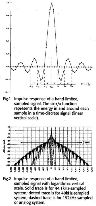
Fig.1 Impulse response of a band-limited, sampled signal. The sinx/x function
represents the energy in and around each sample in a time-discrete signal (linear
vertical scale).
Fig.2 Impulse response of a band-limited, sampled signal with logarithmic vertical scale. Solid trace is for 44.1kHz-sampled system; dotted trace is for 48kHz-sampled system; dashed trace is for 192kHz-sampled or analog system.
After some discussion, I came to the following understanding of Mike’s idea. Look again at fig.1: The mathematical function that describes this graph is sinx/x. It represents the energy in and around each sample in a time-discrete signal, as at the output of a D/A converter before integration (in the smoothing or reconstruction filter). The horizontal axis is the time axis. The large amplitude in the middle fixes the sample amplitude of the sample we’re looking at, S(0). Previous samples S(—1), S —2), etc., as well as following samples S +1), S(+2), etc., fortunately coincide with zero-crossings of S(0)’s sin(x) over graph, as the ringing takes place at half the sampling rate, meaning the zeros are 1/fs (one sample distance) apart (see “Zen & the Art of D/A Conversion,” Stereophile, Vol.9 No.6, September 1986). So no S(0) energy can leak into previous or next samples, as has long been established in digital audio theory. But this holds only for the non-oversampling case.
The situation changes fundamentally once we introduce oversampling to perform digital filtering. Let’s suppose, for the example, that we use 4fs oversampling.
Although the. D/A converter following the oversampling digital filter now runs at 4fs, the digital filter is designed to cut off the passband at our original fs/2 in order to prevent the unwanted 22—88kHz spectral image of the digital audio signal from reaching the analog output. So the resulting sinx/x curve still rings at 22.05kHz, and in fact looks essentially identical to the one in flg.1.
The difference is not in the curve, but in where the samples are. The original samples (as existing before oversampling) will still coincide with the zero- crossings of the sinx/x, but in between every two original samples we now have three new samples, which occur at non-zero moments of the sinx/x function. This way, energy from each original sample is leaking into surrounding (new) samples — deliberately, by the way, because that is what makes interpolation in oversampling work. The problem is that the new samples are not only filled with energy stemming from the directly adjacent original samples, but also from original samples farther away. And that, says Mike Story, smears out the originally well-concentrated energy and causes time smear in the reproduced signal.
Further driving home his point, Mike warned that looking at the amplitude of the sinx/x curve on a linear display is misleading. He then produced fig2: the same sinx/x, but with a logarithmic vertical scale, in dB, which is always more informative in audio. As sound travels at about 340m/s, the 3ms between —1500us and +1500us in the graph represent an acoustical difference of lm. At these points the curve is 80dB down, which is reassuring, but at a moderate —40dB the distance smear is still a non-negligible ±15cm. According to Mike, through this mechanism, high-frequency instruments (which, because of the laws of physics, tend to be small) take on outsize pro portions in the stereo image, which we perceive as unnatural.
Mike Story believes that this is the main reason why the recent new high-speed digital recording/reproduction systems (like dCS’ own) sound more convincing, more natural. If you take another good look at flg.2, you’ll see that other “skirts” have been drawn. The one slightly narrower than the standard 44.1kHz curve results with a 48kHz system. The one remaining just between ±200155 is what happens once you record and reproduce at 96kHz, and the remaining very narrow skirts are with 192kHz sampling and a good analog recording system, respectively.
This explanation is quite different from what many believe is the reason why high-sampling systems sound so good: it is generally accepted that it has to do with supersonic information — instrumental overtones that are cut off in 44.1kHz recording. However, we had some proof that Mike Story might be right when we took part in the following single-blind listening experiment.
We listened to a system consisting of a Nagra-D digital tape deck running at 96kHz sampling. The (digital) output went to a dCS 972 sample-rate converter, its output connected to a dCS Elgar D/A converter in 44.1kHz mode. dCS had programmed four experimental down-sampling filter curves into the 972 sample-rate converter, each of which could be selected by pushbutton switching on the front of the 972.
The four filter curves were, at that stage, identified only as 1,2,3, and 4; we were asked to make notes and (after the listening tests) to explain our preferences. Two minutes of music was played through each of the filters in a 1—2—3—4 sequence while Eelco and I listened and made notes. The sequence was then repeated, but neither of us changed anything of what had been written down.
Robert Kelly, who conducted the test, asked me to respond first. I preferred 3, then 1, then either 2 or 4. Eelco’s list proved to be identical; so were our descriptions of the differences in sound quality Kelly explained that “3” had a very mild slope resulting in a lot less pre ringing, and moderately reduced post-j ringing in the impulse response; “1” was a standard brickwall filter; and “2” and “4” were somewhere in between. “3” does two things: it features lower pre and post-ringing of the impulse (hence lower energy spread, or time smear), and it allows some of the supersonic spectrum (20—30kHz) to pass.
However—and this is the amazing thing—as the Elgar D/A converter was still equipped with its own standard brick- wall filter (—120dB at 22.05kHz!), we could never have heard or otherwise experienced those 20—30kHz! What we had been commenting on must have been the differences between impulse responses, differences in time smear, right through the Elgar’s own time smear!
To get an idea of what digital audio could be without time smear, we then switched the Elgar D/A to 96kHz and connected it straight to the Nagra. The improvement was so obvious that both Eelco and I burst out laughing.
Fourteen years after the introduction of “Perfect Sound Forever,” [as of this articles writing, early 1998] we’ve reached a new and intriguing horizon.
== == ==
Also see: