To Display the Un-demodulated 4.5-mhz FM Sound Signal
Equipment: Low-capacitance probe and scope flat to 4.5-mhz.
Connections Required: Apply probe between "hot" side of 4.5-mhz circuit and chassis ground. Feed probe output to vertical-input terminals of scope.
Procedure: Use 60-cycle sawtooth or sine-wave sweep in scope.
Tune in a TV broadcast station. Adjust receiver controls for normal reception. Adjust scope controls for pattern shown in the following.
Evaluation of Results: In theory, a 4.5-mhz FM carrier with· constant voltage is present in the 4.5-mhz IF circuits. In practice, however, receiver-circuit nonlinearities usually cause amplitude modulation to appear on the envelope of the 4.5-mhz waveform, as shown.
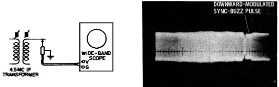
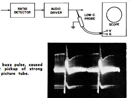
---------- Test setup.
Typical 4.5-mhz I-F signal, showing AM modulation and a vertical sync buzz pulse present on the FM envelope.
NOTE 101
Resonating the Coil Under Test
A probe has a certain amount of input capacitance. When applied across a tuned circuit, such as a 4.5-mhz IF coil, it detunes the coil to some extent. To view the true waveform at that point, the slug in the coil must be turned farther out of the winding to restore 4.5-mhz resonance. The most accurate method of resonating the coil under test is to apply a sweep signal to the receiver with a scope connected at the ratio-detector output. View the resulting S curve, first without the low-capacitance probe applied in the 4.5-mhz circuit; then observe the change in curve height and shape when the probe is applied at the desired test point Retune the coil with the low-capacitance probe connected to restore the original height and shape of the S curve. Then disconnect the sweep generator and make the test described in U81. For details of sweep-generator application, see the companion volume, 101 Ways to Use Your Sweep Generator.
++++++
U82
To Check the Un-demodulated 4.5-mhz FM Sound Signal, Using a Pickup Loop
Equipment: Direct probe, several inches of insulated wire, and wide-band scope flat to 4.5-mhz.
Connections Required: Connect one end of wire to chassis ground. Loop two or three turns of wire around end of 4.5-mhz IF coil form. Connect direct probe between other end of wire and chassis ground. Feed probe output to vertical-input terminals of scope.
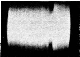
Procedure: Adjust scope controls for pattern shown in U81. Receiver must be tuned to TV broadcast station.
Evaluation of Results: The pickup loop has less detuning effect on the IF coil than the conductive connection described in U81. With a high-gain scope, the 4.5-mhz FM signal can be observed when loop is loosely coupled to the IF coil. AM modulation and sync buzz can be observed with minimum disturbance of the circuit.
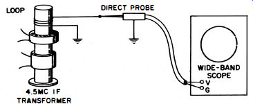
------- Test setup.
+++++++++++
U83
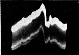
To Check Percentage Modulation of 4.5-mhz FM Signal by the Sync-Buzz Pulse, Using Narrow-Band DC Scope
Equipment : Demodulator probe, several inches of insulated wire, and DC scope (scope can have narrow-band response) . Connections Required: Arrange pickup loop as in U82. Connect demodulator probe between loop output and chassis ground.
Feed probe output to vertical-input terminals of scope.
Procedure: Make sure DC scope is balanced. Receiver must be tuned to TV broadcast station. Short vertical-input terminals of scope to locate the zero-volt level on the screen.
Remove short and observe pattern with respect to zero volt level.
Evaluation of Results: The buzz pulse usually extends downward. The amount it extends downward is a measure of its percentage modulation of the FM IF signal. A ratio detector in normal operating condition can eliminate up to 30% of downward modulation. Higher percentages of downward modulation will pass through the ratio detector and appear in the audio signal as 60-cycle sync buzz.
-------- A sync-buzz pulse downward modulating the FM signal. Scope
is swept with a 60-cycle, sine-wave voltage.
NOTE 102
Effect of Horizontal Sync Buzz
When vertical sync buzz is present, horizontal sync buzz is also present.
However, only the vertical sync buzz is audible. The 15,750-cycle horizontal sync buzz is practically out of range of audibility and becomes choked out in the audio amplifier.
A conventional service demodulator probe also greatly attenuates the horizontal sync-buzz pulses. Hence, operate the scope at 60 cycles sweep when making sync buzz checks.
NOTE 103
Sync-Buzz Pulses Formed in the IF Amplifier
Sync-buzz pulses can be formed in the IF amplifier because of mis-adjustment of the sound trap (s). This misadjustment permits the sound carrier to ride too high on the response curve. Sync buzz can also be generated in the IF amplifier when a stage is overloaded. Overload cross-modulates the vertical sync pulse into the FM sound signal.
Sync buzz also occurs when the video amplifier is overloaded, causing the video signal to modulate the 4.5-mhz FM signal. When sync buzz is generated in the video amplifier, its waveform and voltage change markedly with the setting of the contrast control. Often, this latter type of sync buzz extends upward from the FM envelope, instead of downward.
NOTE 104
Using a Pattern Generator Instead of a TV Signal for Sync Buzz Analysis
A pattern generator can be used instead of a TV broadcast signal to drive a receiver for sync-buzz analysis. The generator signal is steadier than a station signal. The generator must provide normal sync pulses and must have a standard 4.5-mhz tone signal. Adjustable percentage of video modulation is desirable. Sync buzz is most troublesome when the video modulation percentage is high (pattern with white background) . This is because the vertical sync pulse then produces the greatest amplitude modulation of the picture carrier.
++++++
U84
To Check the Action of a 4.5-mhz Limiter
Equipment: Low-capacitance probe and scope flat to 4.5-mhz; or direct probe, several inches of insulated wire, and wide-band scope flat to 4.5-mhz; or demodulator probe, several inches of insulated wire, and DC scope (scope can have narrow-band response) . Connections Required: First, connect loop and/or probe to limiter driving circuit; then connect to limiter output circuit.
Procedure: Observe percentage modulation of 4.5-mhz signal by buzz pulse in first test and compare with results of second test.
Evaluation of Results: The limiter in normal operation prevents downward modulation of more than 30% from reaching the ratio detector. Note that low-priced receivers usually dispense with a limiter stage.
+++++++
U85
To Test for Vertical-Sweep Buzz
Equipment: Same as in U81, U82, or U83.
Connections Required: Same as in U81, U82, or U83.
Procedure: Display pattern using 60-cycle, sine-wave sweep to obtain deflection frequency reference. Turn vertical-hold control.
Evaluation of Results: If buzz pulse remains stationary in the pattern as picture rolls, the buzz pulse is being generated in the IF amplifier or video amplifier. On the other hand, if the buzz pulse moves through the pattern, it is caused by entry of spurious vertical-sweep voltages into the signal circuits. In this event, follow up with scope checks across decoupling capacitors at possible points of buzz-pulse entry to localize the faulty capacitor.
----- A typical vertical-sweep buzz pulse, caused by entry of vertical
sweep voltage into the signal circuits, modulating the 4.5-mhz IF signal.
+++++
U86
To Check for Vertical-Blanking Buzz
Equipment: Same as in U81, U82, or U83.
Connections Required: Same as in U81, U82, or U83.
Procedure: Turn brightness control through its range while watching the buzz pulse for change in height and shape.
Evaluation of Results: If the buzz pulse is responsive to picture tube brightness changes, stray fields from the high-voltage system are entering the signal circuits. Blanking buzz is caused basically by rise and fall of the high-voltage output as the vertical blanking pulse is applied to the picture-tube cathode or grid. In such case, the signal circuits must be better shielded from the high-voltage stray fields.
---------- A buzz pulse in the 4.5-mhz FM sound signal, caused by
signal-circuit pickup of strong stray fields from picture tube radiation.
+++++
U87
To Check for Blanking Buzz at the Ratio-Detector Output
Equipment: Low-capacitance probe.
Connections Required: Apply probe at any point in the audio channel following the ratio detector. Feed probe output to vertical-input terminals of scope.
Procedure: Receiver must be driven by TV broadcast signal or suitable pattern generator. Adjust receiver (and generator, if used) for normal reception. Adjust scope controls for audio pattern, using 60-cycle sweep.
Evaluation of Results: This test should be made if U86 does not show the presence of blanking buzz. Turn brightness control through its range. If blanking buzz pulse is now displayed when brightness control is advanced, stray fields from the high-voltage system are entering the ratio-detector output circuit (audio input circuit) . Better shielding will eliminate the blanking buzz.
------ Test setup.
Typical blanking buzz pulse, caused by audio circuit pickup of strong field from the picture tube.
+++++++++
U88
To Test a Ratio Detector for AM Rejection
Equipment: Square-wave generator, signal generator with built-in modulator (or external modulator unit) , and low-capacitance probe.
Connections Required: Connect square-wave generator and signal generator (with external modulator, if used) for modulated 4.5-mhz output (see V17 and V18) . Apply the signal voltage to the picture-detector output circuit. Connect probe at ratio-detector output. Feed probe output to vertical-input terminals of scope.
Procedure: Adjust square-wave generator output for 30% modulation of the 4.5-mhz CW voltage from the signal generator.
Operate the square-wave generator at approximately 60 cycles. Set signal-generator output for about 0.1 volt.
Evaluation. of Results: Scope should display little or no square-wave output from the ratio detector.
---- Test setup.
Example of poor 60-cycle, square-wave rejection by ratio detector.
++++++++
U89
To Measure the Gain of the 4.5-mhz IF Amplifier
Equipment: AM signal generator and demodulator probe.
Connections Required: Connect generator output cable between 4.5-mhz sound take-off coil and chassis ground. Connect probe output cable to vertical-input terminals of scope.
Procedure: Adjust signal generator for 4.5-mhz output and approximately 30% modulation. Turn contrast control to minimum to eliminate noise interference from receiver signal circuits. Make first test by applying demodulator probe across generator output cable (point 1) . Make second test by applying probe across ratio-detector input circuit (point 2). Note that this detunes the input circuit; for the most accurate measurement, retune to 4.5-mhz (see Note 101) . Evaluation of Results: Make both tests with calibrated scope.
The ratio of the output sine-wave voltage to the input sine-wave voltage gives the gain of the 4.5-mhz IF amplifier.
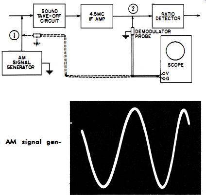
----- Test setup.
Output signal from AM signal generator.
+++