To Display the Vertical Waveform and Measure the Peak-to-Peak Voltage Across a Dynamic Convergence Coil
Equipment: Low-capacitance probe and 0.25-mfd blocking capacitor.
Connections Required: Connect capacitor in series with ground lead of probe (to prevent scope case from being "hot") . Apply probe tip and capacitor across convergence coil.
Feed probe output to vertical-input terminals of scope.
Procedure: To view vertical dynamic convergence waveform, check service notes concerning control settings and disabling of horizontal sweep circuit. Adjust scope controls for typical pattern, as shown in the following.
Evaluation of Results: Compare waveshape and peak-to-peak voltage with data in receiver service literature. (Convergence yoke has separate coils for red, green, and blue guns.)
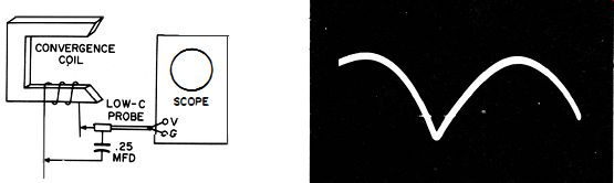
----- Test setup.
Typical vertical dynamic convergence waveform.
++++++++++
U78
To Display the Horizontal Waveform and Measure the Peak-to-Peak Voltage Across a Dynamic Convergence Coil
Equipment: Low-capacitance probe and 0.25-mfd blocking capacitor.
Connections Required: Connect capacitor in series with ground lead of probe (to prevent scope case from being "hot") . Apply probe tip and capacitor across convergence coil.
Feed probe output to vertical-input terminals of scope.
Procedure: To view horizontal dynamic waveform, check service literature concerning receiver control settings. Adjust scope controls for typical pattern, as shown.
Evaluation of Results: Compare waveshape and peak-to-peak voltage with data in receiver service notes. (Convergence yoke has separate coils for red, green, and blue guns. )
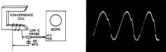
-------- Test setup.
Typical horizontal dynamic convergence waveform.
+++++++
U79
To Check the Waveform and Measure the Peak-to-Peak Voltage of the Drive Voltage to the Horizontal Dynamic Convergence System
Equipment: Low-capacitance or direct probe.
Connections Required: Apply probe between "hot" side of convergence-voltage winding (on flyback transformer) and chassis ground. Feed probe output to vertical-input terminals of scope.
Procedure: Adjust scope controls for typical waveform, as shown.
Evaluation of Results: Compare waveform and peak-to-peak voltage value with data in receiver service literature.
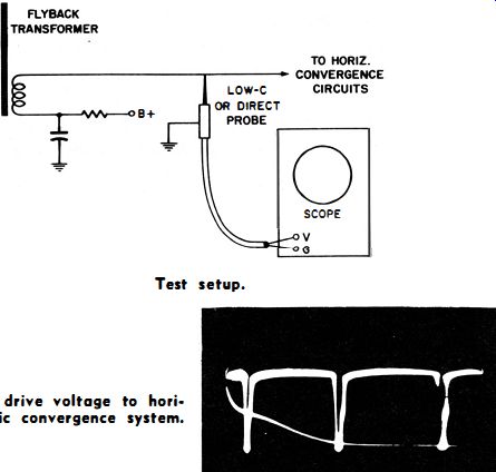
---- Test setup.
Waveform of drive voltage to horizontal dynamic convergence system.
++++++
U80
To Check the Action of a Horizontal Dynamic Convergence Phasing Control
Equipment : Low-capacitance probe and test lead.
Connections Required: Apply low-capacitance probe from "high" side of phasing coil to chassis ground. Feed probe output to vertical-input terminals of scope. Connect test lead to Ext Sync post on scope panel. Drape test lead over picture tube neck near yoke to pick up stray horizontal-sweep pulses.
Procedure: Operate scope on Ext. Sync. Adjust scope controls for typical pattern as shown in the following.
Evaluation of Results: The external sync voltage provides a reference phase point for the displayed waveform. Tune the phasing coil through resonance (with slug or trimmer capacitor provided) and observe pattern for horizontal shift along base line. If phasing control is operating properly, 90° or more phase shift will be observed. If pattern does not shift, coil cannot be tuned through resonance because of a circuit fault. Note that the associated horizontal amplitude control must be turned up from its zero point, or no voltage will be applied across the phasing coil.
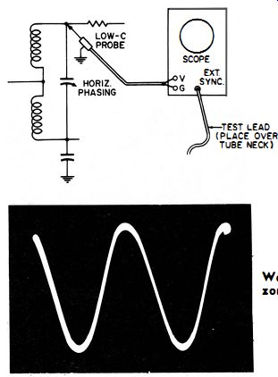
-------- Test setup. Waveform observed across the horizontal phasing control.
+++