This guide is designed primarily for the electronics experimenter; it covers radio receivers and audio amplifiers. In general, the power supplies are not included, since various types can be used and these are covered in another guide.
All of the circuits discussed have been built and tested; some use noncommercial or nonstandard parts. Where this is the case, the part has been described as completely as possible so that it can be made or obtained by the builder. Because the field of transistors is growing rapidly and because new devices as well as new and different designations for old devices are appearing constantly, it is possible for you to substitute parts and still have a working unit.
Usually, the resistors, capacitors, and inductors that are used as a part of the circuit should be as close as possible to the given values. For example, wattage ratings given for resistors, are for conditions of normal ventilation. There are some deviations, of course, that can be made, such as using larger or smaller capacitors than specified in a filter circuit. But, if an electrolytic capacitor has a higher voltage than specified, it may not properly "form" at the circuit working voltage. In most cases it is good practice to at least build the circuit as it was originally built and tested before an experimentation or parts substitution is made.
These circuits have been contributed to the guide by semiconductor manufacturers, and in some cases the semiconductors carry a "house number," which is an unregistered number used for a developmental transistor. In every case these transistors are available, either under the number as given in the guide, or perhaps under a registered number where the manufacturer has gone into large-scale commercial production.
Lead dress and care in construction is critical, particularly in the high frequency, or front, end of these receivers. The construction of many of these circuits requires a considerable amount of experience on the part of the experimenter. This is necessarily true for both receivers and transmitters, but it is not quite as necessary for audio amplifiers, since the lead dress and placing of parts is not usually as critical as it is in radio-frequency circuits.
Because circuit layouts will in most cases vary with the requirements, no specific mechanical details are normally given for the parts layouts. Where these details are given, it is because they are particularly important to the circuit being discussed. Circuit performance depends on the quality of the components selected as well as the care used in the layout and construction of the circuit. To obtain the best signal reproduction from receivers and amplifiers, quality speakers, transformers, chokes, and transducers (microphones and phonograph pickups) must be used.
Parts for the receiver circuits may be obtained by specifying the required characteristics of the desired components. When ordering r-f coils, the circuit location (antenna or interstage), tuning range, and tuning capacitance should be given. For i-f coils or transformers, the intermediate frequency, circuit location (first if, second if, etc.), and possibly the transistor used with the coil should be specified. For oscillator coils, the receiver tuning range, intermediate frequency, type of converter transistor, and type of winding (tapped or transformer-coupled) should be known and included in the data given to the supplier.
Table 1 gives a list of the manufacturers who make the indicated components.
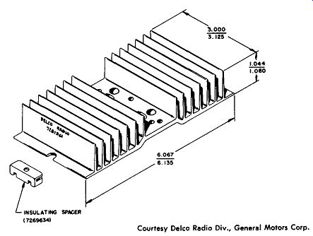
Courtesy Delco Radio Div., General Motors Corp.

Fig. A. Delco 7281361 heat sink.
--------------
Table 1. Component Manufacturers
Tuner assemblies Transformer cores Transformers-i-f, r-f, and r-f chokes
Transformers-audio and power
1. Automatic Electric Sales Corp. 400 N. Wolf Road Northlake, Ill.
2. Arnold Magnetics Corp. 6050 West Jefferson Blvd. Los Angeles, Calif.
3. Better Coil and Transformer Corp. Goodland, Ind.
4. Columbus Process Co., Inc. Columbus, Ind.
5. Indiana General Corp. Crows Mill Road Keasby, N. J.
6. General Instrument Co. Automatic Manufacturing Division 65 Governeur Street Newark, N. J.
7. P. R. Mallory and Co., Inc. 3029 East Washington St. Indianapolis, Ind.
8. Magnetic Metals Co. Hayes Avenue at 21st Street Camden, N. J.
9. Microtran Co., Inc. 145 East Mineola Avenue Valley Stream, N. Y.
10. Mid-West Coil and Transformer Co. 1642 N. Halstead Chicago, Il.
11. J. W. Miller Co. 5917 South Main Street Los Angeles, Calif.
12. Stancor Electronics, Inc. 3501 West Addison Street Chicago, Ill.
13. Triad Transformer Corp. 4055 Redwood Avenue Venice, Calif.
14. TRW Electronic Components, Div. Thompson-Ramo-Wooldridge, Inc. Davis and Copewood Streets Camden, N. J. 08103
15. Thordarson Meissner, Inc. 7th and Bellmont Mt. Carmel, Ill.
16. United Transformer Corp. 150 Varick Street New York, N. Y.
17. Workman TV Products, Inc. Box 5397 Sarasota, Florida
18. Merit Coil & Transformer Corp. 2040 Sherman Street Hollywood, Florida
---------------------
POWER TRANSISTORS
Power transistors require special considerations; they are very rugged devices and can undergo considerable rough treatment, although unnecessary mechanical shock is to be avoided. It is important to avoid extreme shock or excessive bending or twisting of the power transistor leads when they are being used. When operated within their normal ratings, power transistors provide a long and useful life. But, even small excessive voltage or excessive power demands may possibly destroy the transistor instantaneously.

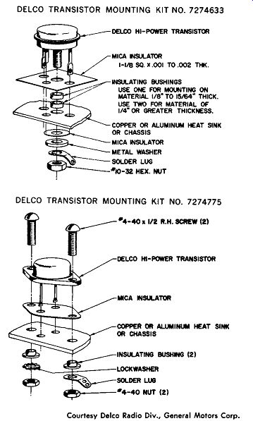
Fig. b. Mounting transistors on heat sink. Courtesy Delco Radio Div.,
General Motors Corp.
When you are building or experimenting with new circuits, it is important to take certain precautions. Before applying power to a circuit, the polarity of the power-supply voltage should be checked and then rechecked. A voltage of incorrect polarity applied to a circuit can damage the transistors as well as any electrolytic capacitors that are used in the circuit. After a new circuit is built and is being tested, the voltage should be applied in easy stages, beginning with a value below normal. Check the basic wiring to see if the circuit operation is correct. It is important to be very careful of high-voltage surges at all times. If the 12-volt electronic power supply that you are using is unregulated, it is possible to load this power supply with a storage battery in order to stabilize the voltage. If the circuit appears to be operating properly, the collector current in the power transistor stages should be measured, and the bias adjusted if necessary.
Temperature extremes can be damaging to a transistor. Power transistors should usually be mounted on a heat sink or radiator.
Where the collector is above ground potential, the sink should be insulated from the chassis; if possible, bolt the transistor to the chassis with insulated bolts and use a washer between the transistor and chassis.
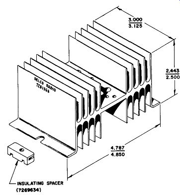
Courtesy Delco Radio Div., General Motors Corp.

Fig. C. Delco 7281366 heat sink.
Excessive heat is an enemy of power transistors. Since heat in creases the collector cutoff current thus reducing the power output, further heat is then developed; it is possible that thermal runaway may result. A circuit can be stabilized by using a thermistor or temperature-sensitive resistor in the base circuit so that an increase in temperature decreases the base-to-emitter voltage and stabilizes the collector cutoff current.
Transistor heat sinks are necessary in many power-transistor applications. Fig. A shows the Delco 7281361 heat sink made of extruded aluminum. This has a nominal weight of 8 ounces and a surface area of about 110 square inches. The mounting of two different types of transistors in this heat sink is shown in Fig. B. The use of these mounting kits allows the insulated mounting of transistors to this heat sink.
The effectiveness of a particular heat sink depends on the contact interface between the transistor and the heat-sink surface. It is necessary that the most intimate contact be made for heat transfer, and the effectiveness of this contact depends on the meeting of the surfaces and the pressure holding them together. The use of a grease or oil is useful in minimizing the effect of any surface irregularity where the two surfaces meet. A suggested type is silicone oil, type 200 (Dow Coming Corp., Midland, Michigan). A different type of heat sink (Delco type 7281366) is shown in Fig. C. This type of heat sink has an insulated spacer which is used to insulate the entire heat sink from the chassis. The transistor can be mounted directly to the heat sink rather than using a mica insulator which insulates the transistor from the chassis but does not act as an effective heat contact. Nominal weight is 10 ounces, and there is a surface area of 165 square inches.