SIGNALING SYSTEM
This circuit shows a unijunction transistor type 2N2646 used as an audio oscillator driven by a 30-volt positive supply. This circuit is suggested for use as a signaling system in the home. Three push buttons are shown; one for the front door, one for the side door, and one for the back door. One or more remote speakers can be connected between base B1 and ground to provide audio indication when any of the push buttons are depressed.
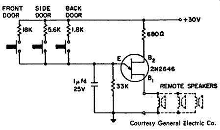
----------- Signaling system.
MOBILE PUBLIC-ADDRESS SYSTEM
This is a six-transistor mobile public-address system designed for use with a crystal microphone and requiring a 12-volt power supply.
There are three stages of voltage amplification, each stage using a 2N180 transistor. The third voltage amplifier feeds a 2N255 driver, which, in turn, feeds a pair of push-pull 2N256 power-output transistors. These two transistors operating in class-B fashion can provide 10 watts of audio power.
This unit is designed for use directly from a 12-volt automobile battery without using a converter or vibrator. As shown in the circuit, a negative ground is indicated for the automobile battery.
Actually, this circuit has a positive common which is bypassed by a large capacitor.
NOTES:
1. Lower gain transistors, such as the 2N107, GT222, and CK722, may be substituted for 2N180 units.
2. For dynamic microphone, eliminate transformer and connect at point indicated.
3. Argonne AR-100.
4. TRIAD TY-61X, ACME T-24042, LAFAYETTE TR-85, ARGONNE AR504, N. E. 2252.
5. TRIAD TY-64X, CHICAGO TAMS-12 (24 to 32 ohms input to speaker impedance, 10 watts).
6. Thermistor required to protect transistors when subjected to high temperature:
VECO 21 W1 (100 ohms, -3.77,_/0C)
7. All resistors are 1/2 watt units except as noted.
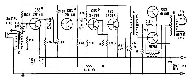
------------ Courtesy CBS Electronic Div., CBS Inc. Mobile PA.
5-Watt 150-Mhz AMPLIFIER
This circuit shows a special type of high-frequency amplifier, the L-52 transistor, used in a 5-watt, 150-mhz, class-C circuit. Both the input impedance and the output impedance are 50 ohms, and the supply voltage is 28 volts. Input bias is varied by adjusting resistor R1, while the output to a 50-ohm load is from the center tap of the output tank circuit.
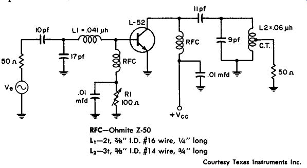
-------------- Courtesy Texas Instruments Inc. 5-watt 150 -mhz amplifier.
SQUELCH AMPLIFIER
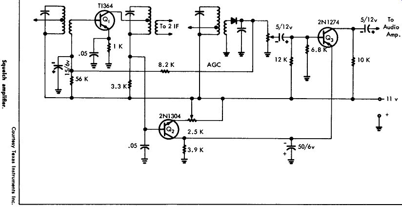
This circuit shows how to use a squelch amplifier to mute a receiver until a signal is being received. When a receiver has a circuit such as this, there is no audio output from the speaker or earphones until a station is being received.
Transistor Q1, a TI364, is an i-f amplifier which has automatic gain control applied; thus, the current flow through this transistor depends on signal strength. The Q1 current is used to control the bias on the squelch transistor Q2; the squelch-transistor amplifier controls the current through transistor Q3, the audio amplifier.
If no signal is being received, Q3 is shut off, and there is no audio output. However, when a signal is received, Q3 conducts to allow the audio to pass to the output stages. A variable resistor used in the Q2 emitter circuit is used to establish the minimum signal that will bias the audio amplifier on.
This circuit will squelch up to approximately a 300-microvolt signal, while maintaining control over very small signals of approximately 1 microvolt. Not shown in the circuit are the parameters for the i-f amplifiers. These are the i-f amplifiers used in the present receiver to which this squelch amplifier can be adapted.
------------------
160- Mhz POWER AMPLIFIER
This circuit shows a single 2N2863 used in a class-C amplifier circuit operating at 160 megacycles, with a power output of 750 mw and a supply voltage of 30 volts. This circuit has a 3-db bandwidth of 15 megacycles, and an efficiency of 25 percent. A matching net work is used in both the input and output circuits to reflect the correct impedance for the transistor for optimum performance in this type of operation. A 2" x 2" x ½" aluminum plate attached to the transistor is used as a heat sink.
This circuit was constructed on a 0.032" brass chassis, and a metal shield was used between the collector and emitter pins of the transistor socket. Both the input and output impedance of this circuit are 50 ohms.
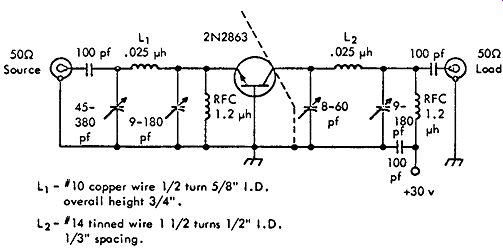
---------------- Courtesy Texas Instruments Inc. 160-mhz power amplifier.
AUTOMOBILE TURN-SIGNAL MINDER
Two circuits are shown that can be used for audio turn-signal minders for automobiles operating from a 12-volt battery. The circuit in Fig. A is similar to the circuit in Fig. B in that both use separate 2N2160 unijunction audio oscillators together with a common audio amplifier type 2N321 and a 3.2-ohm speaker. In Fig. A the right and left -12 volts are tapped from the right and left flasher lights, which are on the automobile dashboard. Note that this circuit is to be used with a positive 12-volt ground. Fig. B shows a negative 12-volt ground in which the right and left + 12 volts are tapped off the right and left flasher lights. In both circuits the IN4009 diodes are used to prevent a short-circuit.
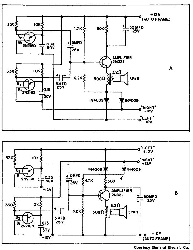
------------ Courtesy General Electric Co. Automobile turn-signal minder.
C-W MONITOR
This circuit shows a 2N646 unijunction transistor and a 1N4009 diode detector operating as a c-w monitor. The various outputs are a speaker, a pair of phones, a phone jack and speaker, or phones and a speaker in parallel. Note that no power source is necessary other than the coupling to the transmitter from which the monitor obtains the necessary drive.
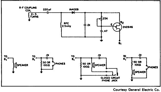
--------------- C-w monitor. Courtesy General Electric Co.
160-Mhz AMPLIFIER
This circuit shows a radio-frequency amplifier operating at 160 megacycles using the developmental type transistor BFY-44 (Amperex Electronic Corp). The input and output impedances are both 50 ohms, and a 28-volt d-c power source is required. The inductor L1 is 3½ turns of No. 16 wire wound in a ¼-inch diameter coil, with a tap 1 turn from ground. L2 is 3 ½ turns of No. 16 wire wound in a 1/2-inch diameter coil. Variable capacitors C1 and C4 are adjustments for the input and output impedance, while capacitors C2 and C3 are used to adjust for the operating frequency.
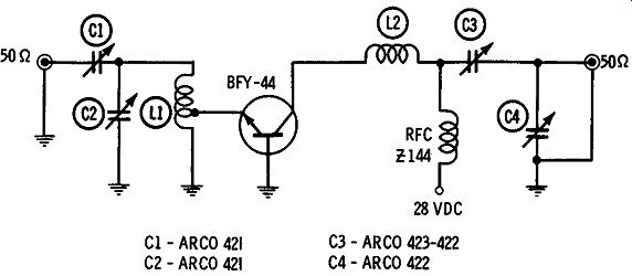
---------------- Courtesy Amperex Electronic Corp. 160 -mhz amplifier.
METRONOME CIRCUITS
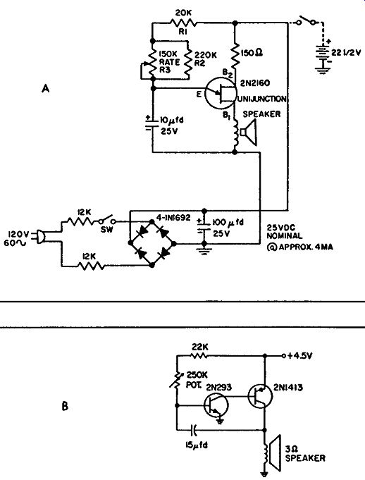
Fig. A shows an a-c powered unijunction audio oscillator, or metronome, using a 3- to 5-ohm speaker for the audio output. A 22.5-volt battery can be used if a portable unit is desired. R1 is used to adjust the high-limit rate, R2 is used to adjust the low-limit rate, and R3, which is a log taper (IRC Q13-328 or equal), is variable for the rate adjustment from about 40 to 220 cycles, or beats, per minute. A simpler circuit using a 2N1413 with a 4.5-volt d-c source is shown in Fig. B.
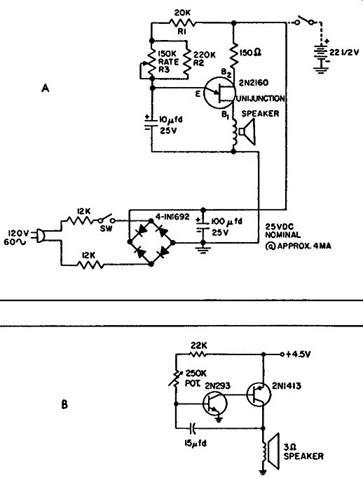
----------------- Courtesy General Electric Co. Metronome-circuits.
100-Mhz AMPLIFIER
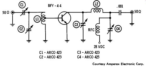
This circuit shows a 100-mhz amplifier using a single BFY-44 (Amperex Electronic Corporation) transistor. The input and output impedance are both 50 ohms, and a 28-volt d-c source is required.
Inductor L1 is comprised of 4½ turns of No. 18 wire wound on a 3/16-inch diameter coil, with a tap one turn from ground. Inductor L2 is 4½ turns of No. 16 wire wound to make a 3/8-inch diameter coil that is 9/16-inch long.
--------------- Courtesy Amperex Electronic Corp. 100 -mhz amplifier.
LOW-LEVEL D-C AMPLIFIER
This circuit shows a special low-level d-c amplifier using three transistors: a 2N2642, a 2N2643, and a 2N2805. Each of these types is a dual transistor. Each of these units is both a pnp and an npn transistor in a six-lead case. These transistors are designed for special applications such as this to provide stability and high gain with a few stages. In this amplifier the common-mode rejection ratio is greater than 120 db, with a low-frequency voltage gain of 68 db and a gain bandwidth product of 5 Mhz. Circuits such as this are used in instrumentation and in analog computers to provide a differential voltage amplification.
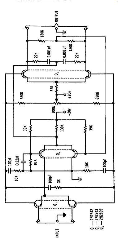
--------------- Low-level ck amplifier. Courtesy Texas Instruments Inc.
VARACTOR TRIPLER CIRCUIT
This circuit shows a technique for tripling a radio-frequency signal. A varactor type H-4A is used, and the output frequency of 240 Mhz is three times the input frequency of 80 Mhz. Input and output impedance is 50-ohms.
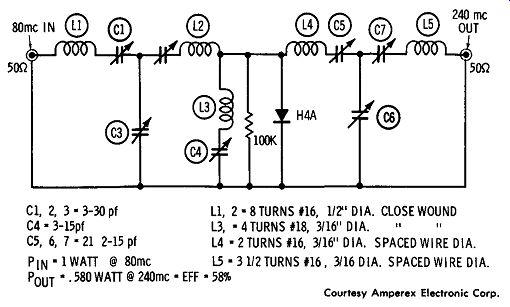
--------------- Courtesy Amperex Electronic Corp. Varactor triple, circuit.
WIDE-BAND AMPLIFIER
This circuit is a wide-band amplifier showing the use of the Darling ton semiconductor device, 2N997. This device is a combination of two direct-coupled transistors, and this circuit is suited to low-noise, high input-impedance applications as an a-c amplifier.
The 2N997 is the input stage and the large bandwidth depends in part on the 2N930 transistors used in this amplifier. The bandwidth is broadened by placing a feedback around the last three stages, as shown, and by reducing the stray capacitance around the circuit of Q1 and Q2. There are two d-c feedback loops for bias stability; one is from the emitter: of transistor Q4 to the base of transistor Q1, while the other is from the emitter resistor of transistor Q5 to the emitter of transistor Q3 • With the feedback capacitor as shown this amplifier has a gain of about 40 db from 30 cycles to 100 khz. Without the feedback capacitor, the gain is the same value from about 30 cycles to about 50 khz.
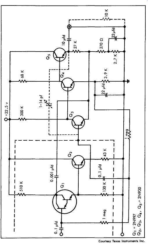
------------- Courtesy Texas Instruments Inc. Wide-band amplifier.
50-Mhz AMPLIFIER
This circuit shows the developmental transistor BFY-44 ( Amperex Electronic Corporation) used in a 50 -mhz amplifier with a 50-ohm input and a 50-ohm output. In this circuit inductor L1 is 6 turns of No. 18 wire wound in a coil with a ¼-inch diameter, with a tap 2 turns from ground. L2 is 5 turns of No. 16 wire wound in a 3/16-inch diameter coil ½-inch long.
---------------- Courtesy Amperex Electronic Corp. 50 -mhz amplifier.
50-KHZ AMPLIFIER
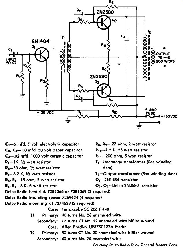
This circuit provides 200 watts of output at 50 khz and is flat within 3 db, with reference to 50 khz, from 25 khz to 68 khz. A single driver stage, which is a 2N1484 operating class A, drives the class-B 2N2580 power transistors. A 150-volt power supply with a 3-ampere rating is required. With no signal input the current required by the amplifier is about 150 ma.
The class-A driver has 25 volts of bias from collector to emitter, with a collector current of 40 ma. The class-B output stage has 150 volts from collector to emitter and a peak collector current of 3 amperes. Output impedance is 72 ohms, and the driving power required is about 0.5 milliwatt. In this circuit it is necessary that appropriate heat sinks be used for the power transistor; suggested heat sinks are Delco types 7281366 and 7281369.
Resistors R1 and R2 are used to bias the driver stage; the resistor in the emitter is used for temperature stability. Transformer coupling is used to provide the necessary impedance match. Resistors R4 and R5 are used to limit the power-transistor base current. As shown, 50 ma of collector current will be obtained in the output stage, with resistors R4 R5, R6 and R7 used to reduce any crossover distortion.
Bypass capacitors C2 and C3 are used across the bias resistors, while resistors R5s and RD are used for high temperature stability. Capacitor C4 will filter any high-frequency transients; the output transformer will match a 72-ohm load.
Ra, 19-.27 ohm, 2 watt resistor
R10-1.2 K, 25 watt resistor
C1 -6 mfd, 5 volt electrolytic capacitor
C2, C5-1.0 mfd, 50 volt paper capacitor
C4 -.02 mfd, 1000 volt ceramic capacitor
R1-1K, ½ watt resistor
111 -200 ohm, 5 watt resistor
T1-lnterstage transformer (See winding 12-33 ohm, ½ watt resistor data)
15-6.2 K, ½ watt resistor
R4 , 15 -15 ohm, 2 watt resistor
T2-Output transformer (See winding data)
Q1-2N1484 transistor
R 6 , 17-6 K, 5 watt resistor
Q2 , Q5-Delco 2N2580 transistor Delco Radio heat sink 7281366 or 7281369 (2 required)
Delco Radio insulating spacer 7269634 (4 required)
Delco Radio mounting kit 727 4633 (2 required)
Core: Ferroxcube 3C 206 F 440 T1 Primary: 40 turns No. 26 enameled wire Secondary: 12 turns CT No. 22 enameled wire bifilar wound Core: Allen Bradley U2375C127A ferrite
T2 Primary: 50 turns CT No. 20 enameled wire bifilar wound Secondary: 40 turns No. 20 enameled wire
--------
Courtesy Delco Radio Div., General Motors Corp. 50-khz amplifier.
10-Mhz VIDEO AMPLIFIER
This circuit shows a 10 -mhz video amplifier using two 2N741 transistors. The amplifier produces a gain in excess of 50 db, with a 3-db bandwidth of 10 Mhz. The power source is 15 volts de, and the input impedance is 1.5K with a load resistance of 1K. This circuit, as shown, has a noise figure of approximately 3 db and a current drain of 20 ma at 15 volts.
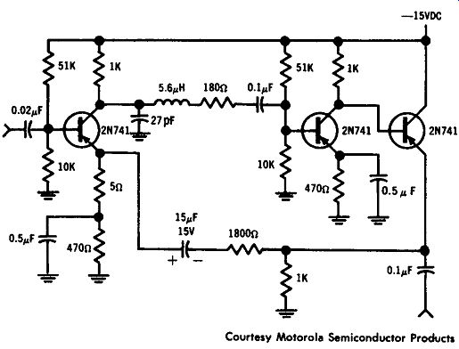
--------------- Courtesy Motorola Semiconductor Products. 10 -mhz video amplifier.
---------------
SPEECH CLIPPER
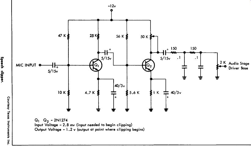
This circuit shows a two-transistor speech clipper using type 2N1274 transistors. This circuit amplifies and clips audio voltage applied at the microphone input. This circuit also filters the high frequency harmonics, and then the audio is fed to the driver stage of a modulator for a transmitter.
This speech clipper is designed to be used with an amateur radio transmitter, and the input voltage where the clipping begins is 2.8 millivolts and the output voltage is 1.2 volts. The result of using a speech clipper is a higher average power output using an a-m transmitter, without going beyond the 100 percent maximum modulation percentage.
Q1 is a class-A common-emitter amplifier used to increase the amplitude of the microphone audio before it is clipped. Q2 is the clipper transistor whose collector-to-emitter voltage and collector current are set to clip both sides of the audio wave. A 50K control in the collector is used to adjust the level of clipping.
450-Mhz R-F AMPLIFIER
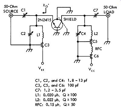
This circuit shows a 2N2415 pnp diffused-base germanium transistor operated as a 450-megacycle r-f amplifier, with a 50-ohm input and a 50-ohm output. This circuit, as shown, has a positive 6-volt supply to the emitter, and a negative 6-volt supply to the collector. The circuit gain is 13 db with a 20-mhz bandwidth and a noise figure of 3.9 db. Proper operation of this circuit requires adjustment of the variable capacitors.
--------------- 450 -mhz r.f amplifier. Courtesy Texas Instruments Inc.
160-Mhz DRIVER-FINAL
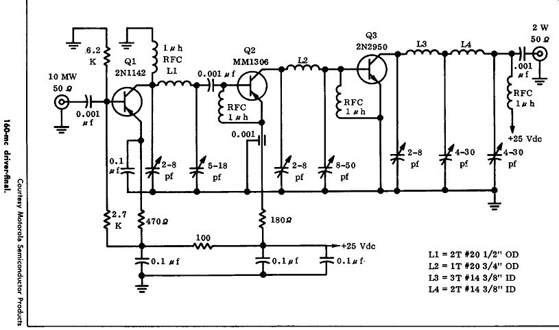
This circuit shows a three-transistor 160 -mhz output circuit that will produce 2 watts with a gain of 23 db. Transistor 01, a 2Nl 142, is operated class A and has an output power of 100 mw. This stage feeds transistor 02, which is an MM1 306 germanium mesa transistor with high-frequency characteristics. A 180-ohm resistor is used to prevent the d-c voltage from exceeding 15 volts. The typical output power for this stage is 550 mw.
The third stage, which is the final, is Q3, an npn 2N2950 on-off amplifier transistor. This stage provides 2 watts of power at 160 mhz, with a power gain of 6 db.
----------------
----------------
Courtesy General Electric Co. 100- khz crystal standards.
----------------
------------------ 30 mhz amplifier (cont'd)
100-KHZ CRYSTAL STANDARDS
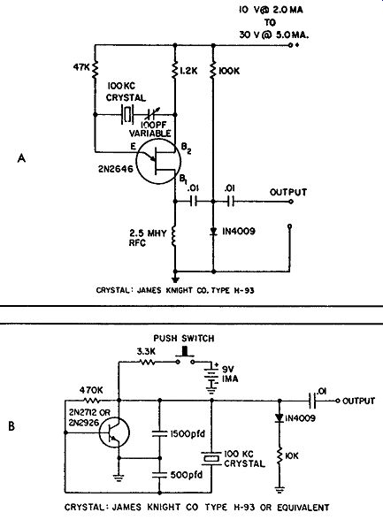
These circuits show simple devices that can be used to provide a 100- khz standard frequency for calibration and other purposes. The circuit shown in Fig. A uses a 2N2646 unijunction transistor, and it operates from any voltage from 10 to 30 volts. The output is a strong 100- khz signal. The circuit in Fig. B shows a transistor type 2N2712 or 2N2926 transistor operating as a crystal-controlled oscillator. This circuit shows a 9-volt power source and a push-to-operate switch. When the switch is pushed, a 100- khz output signal is available.
30-Mhz AMPLIFIER
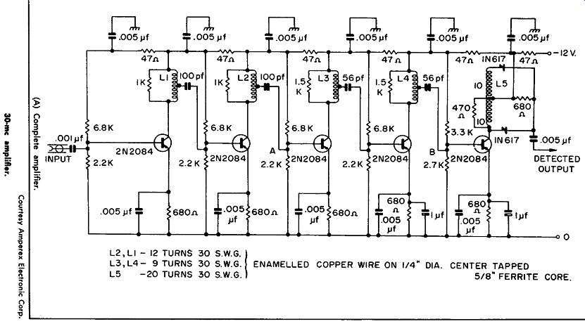
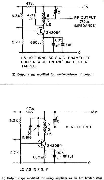
This circuit shows five 2N2084 transistors used in a 30 -mhz wide band amplifier. This amplifier has a gain of 60 db and a bandwidth of 15 Mhz. The transistors used in this equipment are germanium PADT transistors especially designed for high gain, high-frequency operation. Fig. A shows the complete amplifier with a balanced detector used to reduce the amount of rf in the output. Fig. B shows a modified output to produce a 75-ohm output impedance, and Fig. C shows the modification of the output stage to allow the amplifier to be used as a limiter in an f-m system.
This amplifier uses stagger tuning, where one stage is tuned to the center frequency, a second stage is tuned above the center frequency, and a third stage is tuned below the center frequency. Since more than three stages are necessary to provide the required gain in this amplifier, one stage is tuned to the center frequency, two stages are tuned above and two stages are tuned below. The center frequency of these stages from the front end to the output is 25.4, 25.4, 36.8, 36.8, and 30.0. This arrangement provides the necessary overall 15 mc bandwidth at the center frequency of 30 Mhz.