BLOCK DIAGRAMS: Television receivers usually employ many more circuits and tubes than other types of entertainment and communication sets. For this reason, functional or "block" diagrams are frequently employed in service literature as an aid in analyzing the more complicated circuit schematic diagram.
Any particular receiver can be represented by a block diagram in which the various tubes and their functions are represented by individual blocks. The attempt has been made in Figures 134 and 135 to present generalized block diagrams of those elements of both electrostatic and electromagnetic systems which have been covered to date. It will be realized that the choice of one particular television system for presentation must involve only one means of accomplishing the desired circuit operations and that different diagrams may be drawn for other circuit combinations.
The block diagram indicates the sequence of circuit performance by means of "flow" arrows between the various boxes which represent distinct circuit elements.
The television service technician is urged to study these diagrams as well as those available in the service literature since they constitute an excellent method of studying the entire television system.
COMPOSITE TELEVISION SIGNAL (A RADIO CARRIER MODULATED BY VIDEO AND AUDIO)

Fig. 134. Functional Block Diagram--Electrostatic Type. Supply, Deflection,
Synchronization and Control Circuits

Fig. 135. Functional Block Diagram--Electromagnetic
Type. Supply, Scanning, Deflection, Sync, and Control Circuits
In our study of the television system up to this point, we have considered the actions of the circuits associated with the picture tube, enabling it to produce a replica of the image focused on the camera tube at the transmitter.
At several points in the text, the statement has been made that as the electron beam is being swept across the screen of the picture tube to produce a horizontal line, it is simultaneously being modulated in intensity in accordance with the video signal. We will now examine the nature of the radio carrier wave with its video (sight) and audio (sound) modulation.
The principles underlying the interception of the waves _by special antennae, R-F amplification, detection, subsequent I-F amplification, and conversion to a modulating video signal, will be covered in the order of signal progression through the receiver.
We have now analyzed those elements of a television receiver which are pulse -controlled or under "slave" action. We can now logically cover those parts of the receiver which accept the transmitted television signal and use it to produce audio and video output voltages.
The television signal is much more complex than broadcast and short wave signals which carry only speech or telegraphic information. In order to understand the reasons for the necessary complexity of the television signal, a short review of the composition of the familiar broadcast band amplitude-modulated carrier will precede the description of the television carrier.
During the amplitude modulation of the carrier wave by speech or music, frequencies higher and lower than the carrier are produced, known as "side-bands". These occur as a result of the beat or heterodyne between the carrier frequency and the modulating frequency.
In the broadcast band for example, the highest modulating frequency for speech or music transmission is approximately 5,000 cycles per second. Thus, if a broadcast station is operating at 1,000kc (one million cycles) the 5,000 cycle top modulation will produce side bands which extend from 1,000,000 cycles minus 5,000 cycles to 1,000,000 cycles plus 5,000 cycles (995kc to 1005kc). A graphic representation of such a double side -band modulated broadcast carrier is shown in Figure 133.
The modulating frequencies encountered in t he video signal of television extend from less than 30 cycles per second to over 4,000,000 cycles per second. It will be interesting to examine the reasons for this tremendous frequency range in the output of the transmitter camera tube.

Fig. 133. Double Side-Band Modulated Carrier Wave. 50 Percent Modulation -- 5,000
Cycle Tone.
As the signal spot in the camera tube sweeps across the mosaic of the iconoscope, the photo cathode of the image dissector, or the target of the image orthicon, approximately 480 lines are scanned in 1/30th of a second.
(Although there are 525 lines per frame only 480 lines contain video modulation due to those lost during vertical retrace.) If the assumption is made that the picture element is square, and that the definition or resolution is the same in both the horizontal and vertical directions, it is possible to calculate the maximum frequency which will be produced.
The ratio of the length of the picture to its height has been set in the R. M. A. and the F. C. C. standards as 4/3. Assuming there are 480 lines in the vertical direction, the number of horizontal dots for equal resolution would be 480x4/3, or 640. Multiplying the number of vertical lines (480) by the number of horizontal dots (640) we obtain a possible maximum of 307,200 picture elements for a single frame.
Thirty frames per second (two 60"'fields) multiplied by this figure of 307,200, produces an upper frequency of 9,216,000 picture elements per second. Fortunately, this figure does not represent the top frequency as will be seen from a consideration of the video signal which would be produced by scanning a checker board, consisting of alternate white and black squares and having 480 squares in the vertical direction and 640 in the horizontal. (See 1'"igure 136.) In the system of television transmission now adopted as standard in the United States, an increase in carrier strength caused. by an increase in video modulating voltage produces a darker spot on the cathode ray picture tube.

Fig. 136. Video Modulation Produced by Scanning a Checker Board in which the
Picture Elements Are the Limit of System Resolution.
(Diagram one-tenth scale)
The brightest spot in the picture corresponds to the lowest modulating voltage. Thus when the scanning beam in the camera tube reaches the edge of a black square at A of Figure 136, the video modulating voltage of the transmitter assumes its maximum positive value and re mains at this value as the scanning action crosses the black portion of the image. At point B the scanning reaches a white area and the modulating voltage changes to its maximum negative value. The video voltage then remains negative until point C is reached; at which point the cycle repeats itself. Since two picture elements have been scanned in this operation to produce one cycle of video voltage, the top modulating frequency required will be one half of the number of picture elements or in this example 4,608,000 cycles (4.6 megacycles) for 9,216,000 picture elements. Since we have used as an example the maximum resolution of the system, in which a picture element has been made the same size as the scanning spot, the video output would be a sine wave as shown at 136C rather than a square wave at 136B . If double side -band modulation, of the type employed in standard radio broadcasting, were to be used in television (see Figure 133), side-bands extending 4.5 megacycles on both sides of the carrier would require a bandwidth for the video signal of 9.0 megacycles. In the early days of television research, when the pictures were of much lower definition (90 lines instead of 525), double side-band modulation was employed. In addition to the band width required for the video carrier, the accompanying sound carrier and a "guard" space must be provided. The Federal Communication Commission has assigned a channel space of only 6 megacycles for each television channel and it is therefore impossible to use the double side-band type of modulation and still retain the definition which is possible in a 525 line picture. other types of modulation, which require less channel space to accommodate the wide band of modulation frequencies encountered in television are; single side--band modulation, and vestigial side--band modulation. (One side-band plus a "vestige" of the other.) In the process of detecting or de-modulating an amplitude modulated carrier, one side band is always eliminated, and the information in the other is amplified and utilized for the production of the picture. The single side-band method requires only half of the space in the radio spectrum for a given maximum modulating frequency as compared with the double side-band method. Single side-band modulation is produced by passing a double side-band modulated carrier through a radio frequency filter network which suppresses the undesired side-band. Although the single side-band method allows the greatest utilization of channel space, it is considered impractical for transmission of television signals, and has been replaced by the vestigial side -band method because:
1. The type of filter which must be employed for the complete suppression of one side-band introduces serious distortion of the low frequency components of the video signal which results in a "blurred" picture.
2. Even though means of correcting the phase shift may be developed, the single side-band method requires extremely accurate tuning of the receiver and a high degree of freedom from oscillator frequency drift. Otherwise, a loss of the low frequency portion of the video modulation results.

Fig. 137. Output Characteristic of a Television Transmitter, the Required
Receiver Response Characteristic, and the Block Diagram of the Essential Elements
of the Transmitter
VESTIGIAL SIDE-BAND VIDEO MODULATION: The system of modulation employing all of one side -band and a "vestige" of the other has been adopted as standard in the United States to overcome the difficulties encountered with single side-band modulation. The fact that a "part" or "vestige" of one side -band is transmitted gives rise to the name of the method, i. e., vestigial side -band modulation.
Figure 137A shows a typical television channel employing vestigial side-band modulation. Channel No. 3 has been chosen for this example. A block diagram of the essential parts of the transmitter to produce this type of carrier and modulation, is shown in Figure 137C. It will be seen that, in this channel which extends from 60 to 66 mhz, the picture carrier frequency is placed 1. 25mhz above the lower limit of the channel or at 61.25 mhz. Video modulation of this carrier produces an upper side band with frequencies extending to approximately 4mc. The accompanying sound of the program has a carrier frequency 4. 5mhz above the video carrier, or--in this case--at a frequency of 65. 75mhz. A guard channel, or space, of .5mc separates the video modulation from the sound channel. The sound produces a frequency modulation of its carrier with a maximum deviation of 25 khz (a total carrier swing of 50khz). Between the sound carrier and the upper end of the channel (66 mhz) is another guard band, or space, of 0.25 mhz.
It will be noted that the lower side-band frequencies are extended to approximately 1 mhz below the video carrier frequency. For video modulation frequencies extending to 1 mhz the transmitting system is essentially double sideband in character. The presence of the lower side-band would result in an over-emphasis of low frequencies if the response characteristic of the receiver were flat throughout the entire band. To compensate for this possible over emphasis, the receiver characteristic is such that the carrier suffers a loss or attenuation of 50 percent as shown in Figure 137B. The response of the receiver is made to "drop off" at a linear rate from a frequency 1.25 mhz above the video carrier frequency to the lower limit of the band. When the receiver is correctly tuned to the channel, this attenuation of the lower side-band produces a flat output from approximately 25 cycles to 4.5mhz.
When the Federal Communications Commission first announced channel allocations, 13 channels were assigned for television broadcasting. These channels were divided into a low and a high band group. Each channel occupies a band of 6 mhz. The first six channels (1 through 6, inclusive) originally covered a band of 44 to 88 mhz (72 mhz to 76 mhz being reserved for other services). The second group of seven channels (7 to 13 inclusive) covered a band of 174 to 216 mhz. The lowest frequency channel (No. 1, 44 to 50 mhz) has been eliminated from the assigned group, and at this time there is some indication that channel No. 13 (210 to 216 mhz) may also be denied for television broadcasting.
Field experience now being correlated indicates that the original frequency assignments for various cities may cause interference fringes in those sections of the country, where the signal level from a distant city on the same channel is comparable to that of the desired signal. The entire situation is being studied by the F. C. C., and the J. A. T. C. (Joint Advisory Technical Committee). New assignments, reassignments of issued licenses, and the possible opening of new television bands, will await the result of the F. C. C. investigation and hearings. Receivers now in use can be tuned to the channels indicated in the following table.
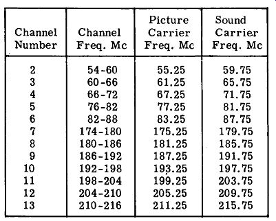
Fig. 138. Channel Allocations for Commercial Television
Figure 139 illustrates the consecutive arrangement of channel spacing, and it will he noted that a guard space of .25mc exists between the sound carrier of the adjacent television channel and the low end of the desired channel. Similarly a space of .25mc is provided between the sound carrier of the desired channel and the low end of the video modulation of the next higher channel. Television receivers must be designed so as to provide a high degree of attenuation or rejection of these un desired transmissions occurring in adjacent channels.

Fig. 139. Arrangement of Consecutive Channel Spacing for Television Channels
2, 3 and 4
THE VIDEO MODULATION: Figure 140 shows the nature of the video signal which would be produced if a card, carrying a series of tones ranging from pure white through a number of gray values to black, were to be placed in front of the television camera. Figure 140A represents one horizontal line scanned across the series of tones. The line is preceded and followed by pedestals upon which are "mount ed'' the horizontal synchronizing pulses . At the left of this figure will be found a scale which indicates the percentage modulation of the carrier corresponding to the various light values. The region from 75 percent to 100 percent is reserved for scanning impulses and therefore the 75 percent point its elf is the blackest part of the picture. The region beyond this black point is known as ''blacker than black'' in television slang. It is also known in engineering circles as the ''infra-black" region.
At the other end of the modulation scale at a value of from 10 percent to 15 percent of maximum amplitude, is found the brightest highlight or "white region". The F.C.C. regulations specify that this white level shall not exceed 15 percent of maximum carrier amplitude. One basic method of receiver design, known as inter-carrier sound, requires for its performance a white level of at least 10 percent of maximum carrier, and, for this reason, television broadcast stations must now hold the white level of transmission within quite narrow limits.

Fig. 140. Video Signal and Carrier Envelope Produced by Scanning a Range of
Tones
The intermediate gray tone s occupy positions between the two extremes just discussed, as shown in Figure 140A and C. Figure 140A shows a series of tones in which the white portion of the picture is at the left and the black portion at the extreme right, while in Figure 140C is shown a succession of white through black to white again, and in this case the black level or pedestal is reached at the center of the active scan.
The television video carrier envelopes which would be produced by the video-modulating waves of Figures 140A and C are shown in Figures 140B and D.

Fig. 141. Variation of Video Voltage Produced by Scanning Line X-X. (Typical
Television Subject)
An actual television subject will be re presented by continuously varying tone values- along each of the 470 to 480 active scanning lines. Figure 141A illustrates a typical .tele vision image. In this case, however, the line structure has been produced by approximately 75 lines rather than the 480 lines of an actual transmission. One of these horizontal lines, which crosses all of the tone values of the subject, has been analyzed for change of video signal due to the major differences in reflected light intensity from the subject. The variation of camera signal, due to scanning the line X-X, results in a video modulating voltage as shown in Figure 141B. The sudden changes caused by crossing such regions as the eyeball-iris pupil "catch light" of the eye, represent rapid excursions of the video voltage. For faithful reproduction of such sudden changes, the sys-tern must have extremely wide band response characteristics. Gradual variations, such as are represented by the slight variations of half-tone values in the flesh tones of the face, and gradual transitions of the shadow in the background c an be accommodated by middle frequencies of the video band.
A number of times in our discussion of video modulation, we have indicated that an increase of carrier strength produces a darker picture until finally the spot on the picture tube is extinguished and produces a black dot. This is known as negative modulation and was chosen by the National Television Standards Committee (a radio industry group, which acted as an advisory committee to the F. C. C .) after trial of positive and negative systems both in the laboratory and in experimental field demonstrations. The reasons for the choice of negative transmission as the United States standard are:
1. Static and noises, both in the receiver and man-made sources, such as automobiles, oil burner ignition, electric razors, etc., should produce black spots on the picture in negative transmission, but would produce bright flashes of light if the video modulation were positive.
The former condition is the least annoying.
2. In the negative system, both horizontal and vertical synchronizing pulses are at maximum carrier amplitude, assuring receiver synchronization with the transmitter even under conditions of low signal strength at the limits of the service area.
Television transmission on a commercial scale has been in progress in Great Britain for a number of years. The British system is based on positive transmission. A comparison of both systems under similar conditions is being conducted in Australia, and the results will undoubtedly be published in the technical publications. Unlike radio broadcasting, which can be received by many types of systems from a simple crystal detector to a complicated super-heterodyne, television is absolutely controlled by the choice of type of trans mission, and for this reason the final decision of the F.C.C. on television standards was delayed for many years pending industry accord.
In the foregoing discussion of the nature of the video modulation caused by scanning the image in the camera tube, we have considered the polarity of the video voltage wave as becoming increasingly more negative as the scene being scanned grows darker. In each case the polarity illustrated (see Figures 140 and 141), is that required for the modulation of the carrier wave. The polarity of the video modulation envelope has been adopted in this discussion as a reference basis rather than the polarity of the camera tube, since the various camera types do not all supply the same output polarity with de crease in intensity of the image.
The television service technician should at this time refer to the discussion of camera tube action covered earlier, since some text books and magazine articles may use, as illustrative material, the output wave of the camera tube rather than the video modulation envelope.
THE DIRECT CURRENT COMPONENT OF THE VIDEO SIGNAL: Video modulation differs basically from the audio modulation employed in sound broadcasting. It is in the form of a varying direct current rather than the familiar alternating current form of speech and music modulation.
The direct current component or "bias" corresponds to the average illumination of the scene being televised. This is equivalent to an average of the camera output for all of the lines comprising a frame-scanning interval. The camera tube itself produces an alternating voltage output which is proportional, at any instant, to the brightness of the particular picture element being scanned at that time. Since the output element of the picture tube (such as the mosaic of the iconoscope) is capacitance -coupled to the input grid of the camera amplifier, it is not possible for any direct current components of the picture tube output to be passed on to the succeeding stages. The remaining video amplifying stages of the transmitter are likewise capacitance-coupled and therefore not able to amplify the direct current component.
Direct current components in the video signal are due to those portions of the scene being televised which have no change in brilliance over a portion of a horizontal line. A uniform gray background, for instance, will produce a uniform, single value charge on that part of the mosaic, representing its image. As the scanning beam of the camera tube crosses this section, no change of output voltage will occur and consequently no alternating voltage will be passed on to the camera amplifier input.
If the average lighting of the scene or background were not taken into account, by the addition of the correct DC bias to the video modulator, the contrast or ratio of brightness of the various parts of the picture with respect to each other would be correct but the back ground illumination or shading would be incorrect.
Several instances of typical television subjects will serve to illustrate the effect on the received image, if the average or DC component were not transmitted:
1. A dancer dressed in a white costume with a black curtain as a background is chosen as the television subject. Let us assume that the television system, from camera tube to the receiving picture tube, has been adjusted so that the dancer's costume is rendered on the picture tube as a satisfactory highlight, and that the black curtain appears as "black". Let us now consider what will happen if several more dancers, similarly garbed in white, come on the scene. If the DC component representing the new average light value of the scene is present both in the transmitted carrier and restored at the picture tube, the scene will be reproduced correctly. If on the other hand the new DC bias were not provided at the transmitter, the highlights of the dancers would be rendered as gray and any gray areas in the background would disappear into the black area beyond cut-off.
2. As an opposite extreme to the example just cited, consider a hockey arena as the televised subject. The system has been set up for proper rendition of the ice as the highlight value. If the opposing teams now skate into the field of view, the large area of dark figures will now degrade the highlight tones of the ice and will, themselves, not be rendered as dark as the actual scene contrasts would require.
To understand the reasons for the effects described in the examples just discussed, we have chosen two types of subject material which, in the abs enc e of the DC component, would produce the same video signal, and would cause confusion in the reproduced image.
Figure 142A shows the video signal from the camera amplifier which is caused by scanning a gray line on a black background. Since no OC component is present, the alternating current is averaged about the line X-X. Figure 142B shows the camera amplifier output when a white line across a gray background is scanned. The contrast between the line and the background is the same in each case and the AC video modulation produced would be the same.
When the video signals in each of these cases are referred to the black level as shown in Figure 142C, the light values are then placed at their proper points on the scale, and no confusion exists. The direct current component caused by taking into account the average value of the background now differentiates the gray line on the black background and the white line on the gray background.
The proper value of OC bias can be produced at the transmitter in several ways:
1. It may be added directly to the modulation circuit by a manually operated control which is monitored by an observer who compares the image on a television screen, with the actual scene being televised and continually adjusts the background or average lighting.
2. An auxiliary camera operated in conjunction with the pickup camera utilizes a photoelectric cell to "integrate" the light of the scene and automatically provide a DC bias for establishing the background level.
3. Certain camera tubes, such as the Farnsworth image dissector, which are non-storage devices, employing a direct coupled output, can produce a direct current component, which is representative of the brightness of the scene. This type of tube is ideally suited to the television transmission of programs directly from motion picture films.
4. Orthicon types of camera tubes, as well as "flying-spot" scanners, can also be made to accomplish DC insertion automatically.
In all of these methods of inserting the DC component or bias level, the end result is the establishment of a fixed DC value for the "black" level of each frame.
In television transmitter practice , the DC component is often added to the video signal in the camera amplifiers, but is subsequently lost by passing the signal through higher level capacitance-coupled video amplifiers. The DC component is then re-inserted by rectifying the peak value of the video signal and adding the rectified DC voltage to the signal.

Fig. 142. Examples of Necessity for DC Component of Video Signal.

Fig. 143. Typical Double Diode "Clamp" Circuit, for Re-inserting
DC at Transmitter

Fig. 144. Block Diagram of Complete Television Receiver. (Electromagnetic Deflection Type)
Note: Portion of Receiver Enclosed in Dotted Lines Covered by Preceding Text. (See Fig. 134)
Figure 143 shows a typical transmitter DC re-insertion circuit. The circuit employs a double diode tube in a bridge network and is known as a "double diode clamp" circuit since it "clamps" the video signal at the black level.
The sync pulses of the video signal establish the level at which this circuit operates. The DC furnished by the circuit for re-insertion is thus referred to a level previously established by the DC component inserted in the camera amplifier.
Figure 144 shows, in block diagram form, all the essential elements of the television receiver from the antenna to the picture tube for "sight" and to the loud speaker for ''sound''. Those portions of the circuit which are shown enclosed by the dotted line are the '' slave circuits''. These circuits include the power supply portions as well as those which control scanning and synchronization. Our study of the television receiver has also covered an explanation of the means for controlling the functions of these circuits.
We will now begin the study of the radio frequency amplifiers, intermediate frequency amplifiers (both video and audio) and the detectors which convert the television carrier wave into audio and video intelligence.
The block diagram of Figure 144 illustrates one particular type of television receiver. Another basic type, in which the sound is not separated from the signal until the combined signal reaches the video output stage (known as the "inter-carrier" sound system), will be covered when we consider video I-F amplification.
Consideration of the balance of the television receiver will be in the numerical order indicated in Figure 144, as follows:
1. The Television Antenna.
2. Radio Frequency Amplifier.
3. The Oscillator.
4. The Mixer or First Detector.
5. First Video and Sound I-F Amplifier.
6. Sound Trap.
7. Video I-F Amplifier.
8. Adjacent Channel Sound Trap.
9. Final Video I-F Amplifier.
10. Video Detector.
11. Automatic Gain Control.
12. Video Amplifier.
13. Video Output.
14. DC Restorer.
15. Sound I-F Amplifier.
16. FM Discriminator or Ratio Detector.
17. Audio Amplifier.
18. Audio Output.