ELECTROMAGNETIC CONTROL
Up to this point, our discussion of beam formation and control has been related primarily to cathode-ray tubes using electrostatic control methods.
A second type of cathode-ray electron beam control is obtained through electromagnetic focusing and deflection by varying the relative force, position, or area of fields adjacent to the beam.
To more easily understand the overall operation of this tube, let us first review the effect of magnetic fields upon an electron beam.
EFFECT OF MAGNETIC FIELDS UPON AN ELECTRON BEAM: The stream of electrons from the beam source may be considered as equivalent to a stream of electrons in a solid conductor carrying direct current. The effect of an external magnetic field upon either stream will be the same since any flow of electrons produces its own magnetic field. The direction of the electron flow and the direction of the magnetic lines it produces are at right angles.
(See Figure 13)
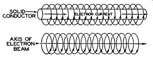
Fig. 13. Similarity of Solid Conductor and Electron Beam.
Should this current-carrying conductor be placed in an existing magnetic field with the conductor parallel to the lines of force of this field, no force will be exerted on the electron

Fig. 14. Conductor Parallel to Magnetic Field stream. The magnetic line s
from the two sources are at right angles, neither aiding nor opposing one another;
therefore, no interaction will result. (See Figure 14)
However, should the conductor be laid at right angles to the existing field, a torque or distortion of t he magnetic lines will tend to move the conductor from the field, since the lines of the two fields are opposing on one side of the current-carrying conductor or stream of electrons, and aiding on the other side. (See Figure 15)

Fig. 15. Conductor at Right Angles to Magnetic Field.
It should also be noted that while Figure 15, for the purposes of illustration, shows the electron stream or conductor at a full right angle with respect to the external magnetic field, that an electron stream entering the magnetic field at any angular variation from the parallel condition of Figure 14 will be affected by the external magnetic field to an extent proportionate to the amount of such angular variations.

Fig. 16. Magnetically Controlled Cathode-Ray Tube.
To apply the foregoing in terms of electromagnetic control of the cathode-ray tube, consider first the construction of this tube (shown in Figure 16) as compared to the electrostatically controlled type. The electron gun assembly is quite similar to that of the electro-static unit. Heater and cathode elements are enclosed in the grid cylinder, as before, and the function of the grid in controlling the number of electrons admitted to the beam is identical.
The anode structure differs in that there is no provision for internal focusing.
An accelerating anode is placed immediately following the control grid cylinder with its connection terminating in the tube base. Another cylindrical accelerating anode is often used connected through contact springs to the aquadag coating on the inner surface of the flared section of the tube. This aquadag coating terminates in a button contact placed on the outside of the flared section.
MAGNETIC FOCUSING: It will be noted from Figure 16 that the focus coil is placed along the neck of the tube, and since the magnetic field of the coil controls the size of the electron beam and causes the formation of a narrow spot of light on the tube face, no internal focusing elements are required.
The construction and application of a typical focus coil is shown in Figure 17.
A coil of wire is wound with soft iron annular pole pieces placed in such position as to concentrate the magnetic field about the neck of the tube, thus surrounding the beam of electrons inside the tube with parallel lines of magnetic force. An annular gap is placed so as to aid the concentration of these magnetic lines.
By concentrating these lines of force, two results are obtained: First, the direct current through the coil is less for a given field strength than would be necessary with other magnetic structures, and second, stray fields are lessened and, therefore, are less likely to affect the action of the other control elements.
Provision is made in television to move the focus coil along the neck of the tube. After it is in its approximately correct position, fine control of focus is obtained by varying the direct current through the coil. This is normally accomplished by using a potentiometer, usually called the focus control.

Fig. 17. Action of Focus Coil.
Referring again to Figure 14, we see that any electrons traveling along a path parallel to the lines of an external magnetic field will not be affected by that field and will continue to travel in a straight line. Axis XY of Figure 17 shows this path.
Referring to Figure 15, we see that a stream of electrons entering an external magnetic field at right angles will be deflected or forced out of the field. Any time this stream of electrons enters the field at an angle away from the parallel condition, some deflection or sidewise movement of the beam will take place.
Lines A and B of Figure 17 represent the paths of electrons which are not parallel to axis XY, and, therefore, since this beam is entering the magnetic field of the focus coil at an angle, a push or sidewise motion of the stream will result. Since the electrons are all traveling at a high velocity, each electron having its own magnetic field, the resulting action of the beam within the focus field will be to take a path similar to the thread of a wood screw. By achieving the proper balance of beam velocity, magnetic field produced by the focus coil, and potential applied to the accelerating anode, the electron beam will leave the focus field in a converging stream having a focal point at the fluorescent screen.

Fig. 18. Action of Deflection Coils
MAGNETIC DEFLECTION: The effect of a magnetic field on fast-moving electrons will be to deflect the beam in a direction which is at right angles to the direction of the field and direction of the electronic motion; therefore, electromagnetic deflection of the beam may be secured by two sets of coils arranged horizon tally and vertically over the neck of the tube near the bulge of the bulb, and located close to the focus coil. (See Figure 16)
The two sets of coils, called deflection yokes, are comprised of four windings, two for horizontal deflection and two for vertical deflection. The two horizontal coils are mounted opposite each other and connected in series for correct polarity, so that the magnetic field passes through the neck of the tube at right angles to the path of the beam and will· be oriented on a vertical plane to secure horizontal deflection. The vertical deflection coils are arranged and connected in the same manner, but oriented on a horizontal plane to secure vertical deflection. (See illustration in Figure 18)

Fig. 19. Deflection coil Assembly (Sample Courtesy of Senn Corporation)
Thus the spot produced by the beam may be moved to any part of the screen by passing the correct amount of current through each set of coils. It is necessary to provide good magnetic shielding between the focus and deflection coils to prevent interaction.
Figure 19 shows coil construction, assembly, and appearance of a complete magnetic deflection yoke.
If a sawtooth of current is passed through the horizontal yokes, it will cause the spot to move from left to right across the screen and flyback; and similarly, if a saw tooth of current is passed through the vertical yoke, the beam will be made to move from top to bottom and fly back. The combined action of the horizontal and vertical fields will produce a frame of light, or raster, similar to that in electrostatic deflection.
A complete discussion of the development of these sawtooth waveforms will be given in a later section of the course covering horizontal and vertical oscillators.
REMOVAL OF IONS FROM ELECTRON BEAM: The emitted electrons from the cathode are mixed with charged atomic particles called "ions". These ions are present in the tube because first, no matter how well the elements making up the internal tube structure are cleansed, some slight amount of foreign material will be present, and second, as the cathode is heated, small particles of it will tend to "break loose". Each ion particle is approximately 2000 times heavier than the electron, and if permitted to strike the screen, a brown spot will gradually appear since the ions will actually remove the phosphor as they strike.
The net result is a spot on the screen where no picture material can be produced, causing a poor viewing condition.
Electrostatically deflected tubes are not affected by the presence of ions since the electron beam and the ions are deflected simultaneously by an electrostatic field. However, magnetic fields do not materially affect an ion, and tubes using magnetic deflection systems must have some provision for preventing the ions from reaching the phosphor coating on the face of the tubes; otherwise, the spot will result.
Two methods are currently used for beam purification when the electromagnetic tube is used. The first method takes advantage of the fact that ions are not affected by magnetism.

Fig. 20. Action of Ion Trap.
The entire beam, containing both ions and electrons, is deflected electrostatically within the gun assembly, and an electromagnet is used to straighten the electron beam allowing the ions to continue on their bent path until they hit an accelerating anode, removing them from the beam. (See Figure 20, which represents a typical "ion trap" assembly.) The field from the ion trap magnets causes the electron beam to be deflected or bent at points X and Y. The ion trap assembly is adjustable to provide a means of bending the beam at these two points. For correct adjustment, the raster is used as an indicator. The entire assembly is adjusted for maximum brilliancy and good horizontal line focus. Thus a stream of electrons only is allowed to emit from the gun structure. These electrons then pass through the neck of the tube, are focused, deflected, and accelerated toward the tube face.
"Bent gun" assemblies are also used in addition to the one illustrated in Figure 20. In either type, the theory of operation is the same.
A second widely used method of beam purification involves the use of an extremely thin film of aluminum placed on the '' beam side" of the phosphor viewing screen. The thickness of aluminum is chosen so as to allow the electrons to pass through and strike the phosphor. Since the ions have greater mass, they will not penetrate the aluminum but will be stopped and, therefore, not strike the phosphor. The use of the "aluminized" screen is also felt to give other advantages, namely, that of providing better contrast and brilliance on the picture screen. Of course the use of this tube eliminates the need for external coils in the beam purification since the beam does not have to be "bent" within the gun assembly.
Figure 21 shows a tube employing the aluminized screen construction.
Figure 22 illustrates a type 10BP4 magnetically focused and deflected tube with ion trap, focus coil and deflection yoke in position as used in a typical receiver

Fig. 21. Type 10FP4 Aluminized Screen Construction (Photo from Sample Courtesy
Rauland Corp.)

Fig. 22. Electromagnetic Tube Assembly in Receiver

Fig. 23. Type 5TP4 Projection Tube (Sample Courtesy RCA)
------------

Right: IMAGE ORTHICON (Photo from sample courtesy RCA)
Right: MONOSCOPE (Photo from sample courtesy RCA)
Left: ICONOSCOPE (Photo from sample courtesy RCA)
Left : IMAGE DISSECTOR (Photo courtesy Farnsworth Television & Radio Corp.)
-----------------------
Some television receivers employ cathode-ray tubes having electrostatic focus and electromagnetic deflection. Such a tube employing this combination is the RCA type 5TP4 projection unit shown in Figure 23.
The general types of picture tubes and their requirements for deflection have been covered. Before discuss in g the method of translating received signals into visual patterns on the face of the picture tube, let us examine the method of converting the televised scene into video signal at the transmitting studio.