In order to reproduce signals recorded on the phonograph record, a transducer (phonograph pickup, phono cartridge, or needle) converts the groove modulation into the electrical signals. Unlike microphones, loud speakers, and other types of devices or transducers that convert one form of energy into another, the phonograph pickup has to perform more than one function. The phonograph pickup or cartridge, so called since the invention of the removable stylus or needle assembly, has to convert modulation of the record groove into the electrical signals, and at the same time support the tonearm at the proper height above the record surface, all the while moving the tonearm across the surface of the record.
The phonograph cartridge is an electromechanical device designed to track or follow the excursions of the record groove and to convert this motion, with the help of a tracking mechanism-stylus assembly, into electrical signals.
Cartridges are classified by the principle by which they convert mechanical motion into the electric current or signal, electrodynamic and piezoelectric. There are also pickups designed to operate using strain gauges, variable capacity, and light as sensors.
Electrodynamic-Type Cartridges. Electrodynamic type cartridges are subdivided into three categories: moving magnet, moving coil, and induced magnet or moving-iron type. The electrodynamic principle consists of using a magnetic field that, when it intersects the coil windings, generates electric current. The construction of the cartridge classifies the type. If the magnet is attached to the stylus tube or cantilever and the coils are stationary, it is called a moving-magnet cartridge. If the magnet is made stationary and the coils move in the magnetic field, it is a moving-coil cartridge; and if the magnet and the coils are made stationary and there is a slug of soft magnetic iron moving in place of a magnet while being magnetized by the stationary magnet, it is called a moving-iron or induced-magnet cartridge.
Variable-Reluctance Cartridges. Since the introduction of the original variable-reluctance pickup, Fig. 18, many different versions of its design have appeared. The magnetic structure consists of two pole pieces A, with a small permanent magnet B between them. The coil C is mounted with a soft rubber insert D.
The stylus, which is also the armature, is held in the exact center of the magnetic structure by the rubber insert. When the stylus is actuated, its movement causes a voltage to be generated in the coil. Because of its construction, the frequency response extends beyond the normal audio-frequency band. Output voltage is on the order of 100 mV at 1 kHz, with an output impedance of 50 ohm. The recommended stylus pressure is 15-20 g. The stylus weighs 31 mg and is removable.
Although the recommended pressure is 15-20 g, the pressure could be as low as 7 g. The frequency response is ±2 dB, 20 Hz-20 kHz.
Moving-Coil Cartridges. Modern moving-coil cartridges are represented by a variety of designs. All of them have coils that move, but not all of them are entitled to be called moving-coil type. Designs that depend for their functioning on the motion of the soft iron core rather than on the motion of the coil itself should not be classified as a pure moving-coil device. There the motion of the coil is coincidental. FIG. 19 shows the cross sections of moving-coil stylus assemblies as they move during the playing of the record. The magnetic flux is directed by the iron core or armature of the coil. If the coil is made stationary and the core is vibrated, the signal will still be generated. This fact prevents it from being classified as a pure moving-coil device.
The advantage of this design is extremely low output impedance, making the cartridge insensitive to capacitive loading and allowing the use of very long cables without altering the frequency response of the device.
On the negative side, the output of the cartridge is very low, measuring in the tenths of a millivolt requiring an extra 20-30 dB amplification to bring the electrical signal to the required level as referenced to an established sensitivity of 1 mV/1 cm/s of recorded velocity.
A step-up transformer or an extra stage of amplification usually introduces additional noise and the effect on capacitive loading. Other drawbacks of such design are the weight of the cartridge and the need to use a heavier tracking force.

FIG. 18. Variable-reluctance magnetic pickup.
One of the debatable points about MC cartridges is the sound they produce. MC cartridges have a very fast response to transients because of the very low inductance and the impedance of the coils and the very rigid cantilever, which has to be strong in order to move a relatively heavy coil assembly. Another factor in this type of design is the construction of the coil assembly, which may have a number of turns in the coil unsupported and free to vibrate, producing random signals at higher frequencies. Also lead-in and lead-out wires may not be secured properly and can vibrate in the magnetic field producing random coloration of the signal. Lead dressing, coil impregnation, and gluing techniques control the purity of the sound produced by this design.
Step-up transformers require winding ratios of 1:10 or more. The transformer's high-impedance secondary winding is reflected back into the primary, and any loading of the secondary in excess of the specified value affects the signal output level and electrical damping of the coils. Theoretically, shorted coils produce maximum damping, while an unterminated winding of the trans former's secondary will emphasize electrical resonances and unchecked mechanical motion. It is important to locate the step-up transformer near the preamplifier input to minimize the capacitive load of the shielded wires between the transformer and the input stage of the amplifier. Because the levels handled by this input transformer are extremely low, good transformer shielding is necessary.
In lieu of the step-up transformer, a pre-preamplifier may be used. Additional preamplification, obtained from active gain circuits, requires super low-noise circuits in order to preserve an acceptable SNR. There have been many such pre-preamplifiers designed using the most exotic devices and circuits, operating with batteries or special ac power supplies with maximum filtering and voltage regulation and using magnetic shielding.
Moving-Magnet Cartridges. The most popular high performance stereo cartridges are the moving- magnet type. Moving-magnet cartridges offer one of the most sensible ways to design the stereo cartridge with a replaceable stylus. This cartridge has low dynamic tip mass, high compliance, and fairly high output. By using the most powerful rare earth magnets and using the most modern manufacturing methods, the frequency response is extended from almost direct current to well past the threshold of hearing, FIG. 20.
Induced-Magnet Cartridges. An example of an induced-magnet or variable-reluctance pickup is manufactured by Bang and Olufsen of Denmark. It consists of a small armature in the form of a cross, made of Mumetal, which swings between four pole pins, Fig. 21A. A stylus bar constructed of aluminum tubing 0.002 inch (0.05 mm) thick is attached to the Mumetal armature cross at one end. The stylus is secured to the other end of the tube. Four pole pins with four coils are placed at each end of the cross. With a 45° motion to the right, a reverse voltage induction takes place. Such action permits the coils to be connected push-pull, thus reducing harmonic distortion induced by the nonlinearity of the magnetic field. In addition, the coils provide an effective hum-bucking circuit.
Crosstalk between the left and right channels is minimized, since such components are bucked out. Modulating one channel 45°, the cross arms on the orthogonal channel rotate without changing the spacing; therefore, there is no induced voltage in this channel, assuming the positioning of the unit, with respect to the groove, is correct.
=====

FIG. 19. Bottom view of the moving-coil cartridge generator assembly.
A. Cantilever in the neutral position.
B. Cantilever deflected to the right.

C. Cantilever deflected to the left.
======
A cross-sectional view of the magnetic circuit is shown in FIG. 21B and is similar to the magnetic structure of a loudspeaker employing a center magnet.
Thus, a closed magnetic circuit, which prevents leakage of the magnetic field, is provided and being nonmagnetic, it cannot be attracted to the steel turntable plate. It also provides an effective shield for the coils. The stylus bar pivots on a nylon thread, bonded to a plastic support. The armature cross bears on a resilient disc, FIG. 21C, which controls compliance and supplies damping for the moving system. The rotational point of the system is at the junction of the armature cross and the nylon thread support. The output voltage is 7 mV for each channel for a 5 cm/s cut. The stylus has an angle of 15° at 2 g of tracking force and may be operated at a pressure of 1-3 g. Compliance is 15 × 10-6 cm/dyn for both directions of motion.
Frequency response is 20 Hz-20 kHz ±2.5 dB.
Semiconductor Pickup Cartridge. A semiconductor pickup cartridge operates on the principle of the strain gauge. The pickup mechanism employs two small, highly doped silicon semiconductor elements 0.008 inch × 0.005 inch whose resistance varies as a function of the stylus deflection, FIG. 22. The elements are mounted on laminated beams of lightweight epoxy with gold-plated surfaces. A notch in the beam under the assembly acts as a hinge for stress concentration. In this structure, two beams are used, each driven by an elastic yoke, coupled to the stylus. Aside from the compliance of the yoke and mounting pads, a mechanical advantage of over 40:1 can be attained in the beam and stylus lever. This mechanical transformer provides high compliance and reduces the mass of the elements reflected to the stylus. The stylus is elliptical in shape and set at an angle of 15°.
========

FIG. 20. Basic principle of the moving-magnet pickup.
Mu-metal shield Isolated para-toroidal coils Laminated coil core with unitized pole pieces Vector-aligned dual magnets
0.12-mm square shank nude-mounted linear contact natural diamond stylus
0.3-mm diameter beryllium cantilever
Radial damping ring at cantilever fulcrum; Individual compliance adjustment screw
=========
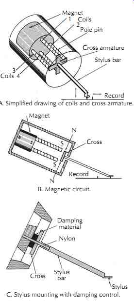
FIG. 21. Induced-magnet cartridge construction.
A. Simplified drawing of coils and cross armature.
C. Stylus mounting with damping control.
B. Magnetic circuit.
Magnet 1 2 Pole pin Cross armature Stylus bar 3 4 Record Coils; Coils Magnet N Cross Record S S N Damping material Nylon Stylus bar Cross Stylus
=========

FIG. 22. Stereophonic semiconductor pickup.
A. Beam construction of a semiconductor pickup.
B. Cartridge construction of a semiconductor stereophonic pickup.
0.008" Encapsulated semiconductor
0.008 × 0.005 × 0.005 element; Strap
0.020" Force
0.020" Hinge; Epoxy; Output gold plated surfaces
0.001" Mounting pad; Coupling yoke; Low mass stylus
0.090" Needle damping pad; Elements; Leads
0.050"
==========
Since the semiconductor elements are sensitive modulating devices and not generators as in the conventional pickup, very little energy is required for their operation. The compliance at 1 kHz is approximately 25 × 10^-6 cm/dyn and the frequency response is from 20 Hz-50 kHz. A power supply, two single-stage preamplifiers, and one inverter stage are required. As the elements are deflected by the stylus action, the resistance of the semiconductors, about 800-ohm changes slightly, causing a varying dc voltage across the output.
This DC signal is AC coupled to the preamplifiers in the power supply, providing an output voltage of 0.4 V for each side. The cartridge employs mechanical equalization that, in combination with the RC equalizer at the output of each preamplifier, results in an RIAA reproducing characteristic.
Piezoelectricity. Piezoelectricity is pressure electricity. The voltage generated by the crystals in piezoelectric cartridges is proportional to the amplitude of the stylus displacement. The output voltage of the average piezo electric pickup is considerably higher than for other type pickups. Piezoelectric pickups are treated electrically as a capacitive-reactance device since the impedance rises with a decrease of frequency. Simple RC networks are used with this type of pickup to obtain a frequency response corresponding to the standard RIAA reproducing characteristic. Records recorded using a constant-amplitude characteristic may be reproduced without equalization.
In the ceramic stereophonic pickup, FIG. 23, the moving system consists of two piezoelectric crystal slabs of lead-zirconium titanate or similar material. This particular material offers good mechanical and electrical properties with high sensitivity and high capacitance.
The ends of the slabs are mounted rigidly in a mounting block, and the front end is connected by a yoke made of injected molded plastic. This coupling is critical because the electrical performance and the mechanical impedance seen at the stylus point by the record groove depends on it. The coupling system is defined as that portion of the mechanism that lies between the stylus tip and the ceramic slabs.
======

FIG. 23. Simplified drawing showing the construction of a ceramic stereophonic
pickup.
Components: Mounting block; Ceramic elements; Stylus; Coupling yoke; Stylus bar; Stylus mounting block
=====
The stylus bar is made from heat-treated, thin-walled aluminum alloy tubing, with one end flattened to hold the stylus at the desired angle. The other end of the stylus bar is held in place by the stylus mounting block.
The coupling yoke is connected at a point about midway on the stylus bar. This point is chosen because it affords the most desirable electrical performance and substantially reduces the mechanical impedance of the yoke and ceramic elements as seen by the stylus tip.
Better designs have four output terminals, two for each channel, to ensure the complete isolation of one side from the other. Damping in the form of a viscous material is used to control the frequency characteristics.
These pickups are of the constant-amplitude type with the output voltage 10 mV for a peak velocity of 5 cm/s.
Ceramic pickups are not affected by magnetic or electrostatic fields.
RC equalizer networks for both crystal and ceramic pickups are shown in FIG. 24. The networks are connected between the output of the piezoelectric pickup and the input of the preamplifier. The characteristics of these networks are such that they correspond to the standard RIAA reproducing curve. Using a pickup with a compliance of 15 × 10^-6 cm/dyn or greater, the response can be within ±2 dB.
The internal impedance of the average crystal pickup is approximately 100 k-Ohm, with a capacitance of 0.001 to 0.0015 µF.
1 Cartridge Styli
Stereo Disc Groove. The playback stylus is the first link between the information stored in the record groove and the playback system. The quality of the reproduced sound is influenced by the precision with which the stylus follows the groove modulation.
In stereophonic recordings with 45°/45° modulation, the two channels are isolated from each other because modulation of each channel is at 90° to the other, FIG. 25.

FIG. 24. Networks for equalizing ceramic cartridges.
To minimize the effects of vertical excursions at low frequencies, the phase of both channels is adjusted so low-frequency signals are in phase in order to produce lateral modulation. The phase relationship of the two channels determines the location of the sound image between the two loudspeakers, and in some cases the phase is a deciding factor as to whether there is going to be a signal reproduced at all.
Stylus Tip. The function of the playback stylus of the cartridge is to follow all deflections of the groove. Since the stylus is attached to the end of the cantilever, any motion of the stylus tip is transmitted to the other end of the tube or shank, where the electrical signals are generated by a moving magnet, a moving coil, or a crystal.
The stylus has rounded off edges that are polished for smooth tracking. Ideally, the playback stylus should be centered in the groove, and its centerline should match that of the cutting stylus. There are always minute imperfections in the alignment of the stylus and of the groove. Therefore the shape of the playback stylus is made to compensate and allow some misalignment of the stylus in the record groove.
The stylus touches the groove walls at two points. The contact area is curved and is a part of the tip radius so that if the stylus is slightly tilted due to misalignment of the cartridge or the tonearm, tracking will not be affected.
Spherical Stylus. There are several types of styli today.
The simplest and the oldest one is the spherical tip. The spherical stylus is a tiny diamond or sapphire cylinder with one end ground to a cone shape with its tip polished to an accurate sphere. The included angle of the cone is about 55°, and the tip radius is about 0.0007 inch or 0.7 mil. Because grooves can be as narrow as 0.001 inch, the stylus tip has to be equal to or smaller than the groove in order to track it. The standard tip radius dimensions for today's spherical styli range from 0.0005-0.0007 inch (12.7-17.7 µm).

FIG. 25. Comparison of 45°/45° stereophonic groove with standard lateral
groove.
Elliptical Stylus. The second type is the elliptical stylus. From the front it looks like a spherical stylus; however, there are two flats polished in the front and the back of the stylus. The side radius of the elliptical tip is much slimmer than that of the spherical stylus. The intersections of the two flats are polished to form small radii called the tracing radii, which measure about 0.0002 inch (5 µm). These small side radii are actually in contact with the modulation of the groove and, because they are small, they follow the high-frequency excursions of the groove more easily.
Stylus Characteristics. All playback styli are designed to contact only the walls of the groove; therefore, the stylus tip has to ride without touching the bottom of the groove. Since the diamond gets slimmer as it wears down, the tip gets closer and closer to the bottom of the groove. When it starts touching it, noise increases because debris has accumulated on the bottom of the groove and is scooped up by the stylus. This is a clue to change the stylus in order to reduce the noise and to pre serve the record from being destroyed by the sharp edges of the worn diamond.
Currently, almost all styli manufactured are made out of diamond. The quality and the price of the stylus depends on whether it is made out of a solid piece of diamond or a small chip bonded onto another material that acts as an extension or pedestal for the diamond tip.
The technology of manufacturing diamonds has advanced significantly so that chip bonding and encasing can be favorably compared to solid or nude diamond tips. In view of the fact that the area of contact is only 0.2 millionths of a square inch (0.2 × 10^-6 inch) and as long as this area is made out of a diamond, the overall performance of the stylus will not be affected.
All this is true providing that the mass of the bonded stylus assembly is not higher than that of a conventional diamond and not larger than the nude stone.
The vertical tracking force applied to the stylus is divided between the two walls. Each wall is experiencing force that is equal to the total vertical force times the cosine of 45° or 0.707, FIG. 26. For instance, if the vertical tracking force (VTF) is 1 g, each groove wall will experience a force of 0.7 g.
=====
FIG. 26. Stylus motion and forces acting upon it in a stereo groove.
VTF 1.0 g Modified stylus direction
Plastic groove indentation
0.7 g 0.7 g
Right channel modulation
======
A very small area of contact exists between the stylus tip and the groove so the pressure against the groove wall can rise up to many thousands of pounds per square inch. For instance, if each wall receives 0.7 g of force applied through the contact area equal to two ten millionths of an inch (0.2 × 10^-6), the pressure is 7726 lb/inch. With such high pressures and force of friction between the stylus and the vinyl, the outer skin layer of the record material melts as the tip slides over the plastic and then refreezes almost as fast as it melted.
Since the melting temperature of the vinyl is about 480°F, the same temperature exists in the contact area.
Stylus Cantilever. The stylus is attached to some type of coupler or cantilever that connects it to the generating element of the cartridge, which could be a magnet, a piece of iron, a coil, or a ceramic element. Because of a very wide range of frequencies this stylus assembly has to transmit, the construction material and shape of the cantilever are very important. Theoretically, it has to be very light and rigid. Over the century of existence of mechanical sound recording, styli were made out of cactus needles, whale bones, and all kinds of metal, gems and stones, plastic, and wood. The final choice is centered around an aluminum alloy thin-wall tube. It is fairly strong, light, noncorrosive, nonmagnetic, electrically conductive, and easy to manufacture.
The average diameter of the aluminum cantilever tube is 0.03 inch (0.76 mm), and the length may vary from ¼-½ inch (6-12 mm). A few exotic cartridges have cantilevers made out of solid ruby or even diamond and some from boron or beryllium copper alloy. Although ruby and diamond are extremely rigid materials, because of manufacturing difficulties and high weight/length ratio, they are made very short. This, in turn, brings the pivot point much closer to the stylus tip that moves in a much smaller arc when reproducing groove modulation. Since the grooves are modulated by the cutting stylus that has its pivot quite a distance away and is moving in an arc of much larger radius, the larger the difference between the motions of the cutting and of the playback styli, the larger the distortion.
On the other hand very long playback cantilevers are unable to produce sufficient motion of the generating element that results in a very low electrical output.
Compliance. The amount of force required to move the playback stylus depends on several factors; the first is the compliance of the stylus, and the second is mass.
Compliance of the cantilever or the stylus is the ability of the stylus assembly to react to the groove modulation. It is measured in cm/dyn or µm/mN (metric) and gives the amount of stylus tip deflection for the given force. Compliance is measured statically and dynamically.
Static compliance is the amount of deflection of the cantilever when a constant force is applied to the stylus tip. Dynamic compliance is a measure of tip deflection as it is reproducing the frequency of known amplitude at which the measurement is being made.
Vertical Resonance. The second variable in the equation is the tonearm/cartridge vertical resonance. Tone arms and cartridges resonate between 5 Hz and 15 Hz; the most desirable range is between 8 Hz and 12 Hz.
Resonance below 8 Hz will produce instability of the tonearm and will result in poor tracking of moderately warped records.
Stereo cartridges have fairly uniform compliance in all planes of stylus motion. Cartridges with higher compliance work best with light tonearms, and heavy tonearms should be set up with cartridges having low compliance. If the stylus compliance is low, the tracking force applied to the stylus should be higher than for a high-compliance stylus.
2 Cartridge Voltage Output
The output voltage of the cartridge depends on its design and the type of generator system used. Ceramic or crystal cartridges produce the highest voltage. Next are the moving-magnet cartridges and then the induced-magnet pickups; the last group is the moving-coil cartridges. The moving coil cartridge produces higher power output than other types so they can work with step-up transformers to increase the output voltage 10-20 times or 20-26 dB. On the other hand, some high output voltage ceramic cartridges are connected to the loss pads and response-shaping networks to reduce the voltage down to the average output level of the moving magnet cartridges. Today most of the preamplifiers are designed to accept moving-magnet cartridges.
3 Electrical Loading
With various output levels and different source impedances, cartridges respond differently to electrical loads.
For instance, crystal or ceramic cartridges are the most susceptible to capacitive loading. The entire frequency response is dependent on the loading of the cartridge. In the moving-magnet cartridge, only the highest portion of the frequency range is affected by the capacitive loading. The moving-coil cartridge is almost completely immune to the loading effects. Once it is connected to the step-up transformers, the secondary of the trans former becomes very sensitive to loading, and excess capacity can play havoc with transformer resonance and the impedance of the secondary transformer winding.
Therefore, cartridge manufacturers specify the recommended resistive and capacitive loads.
The most common resistive load is 47 k-Ohm (50 k-Ohm for Europe), paralleled by 200-400 pF of capacitance for the moving-magnet cartridges, depending on the manufacturer and on the cartridge model. The capacitive loading for the cartridge includes capacitance of all interconnecting cables and tonearm wiring to ground (or between the conductors), capacity added by the connectors and switches. Finally the internal wiring of the preamplifier circuit and preamplifier input circuit capacitance, which varies widely depending on the circuit design, adds capacitive loading to the cartridge, FIG. 27. In many cases the total capacitance that appeared as a capacitive load for the cartridge exceeded 1000 pF, which resulted in an electrical resonance peak around 7-8 kHz followed by premature response rolloff at frequencies above this point.