4. Analog Circuits and Systems
The transport mechanism, heads, and tape should combine to determine the basic performance limitations of a tape recorder. The analog electronic circuits of the recorder, on the other hand, should exceed the capabilities of the heads and tape in all respects so that only the heads and tape limit the quality of the final signal. In practical terms, this means that the SNR, frequency response, distortion, and head room of the electronics are comfortably better than the heads and any tape, including future improved tapes.
The block diagram of the signal electronics of a typical professional audio recorder is shown in Fig. 36. In terms of actual hardware, approximately 75% of the audio circuits of a modern professional audio recorder are devoted to operator interfacing and controls; the remaining 25% implement the basic functions of erasing, recording, and playback. Since the variation of features and technology used to implement the interfacing and control functions is too broad to be summarized herein, the following description covers only the latter basic functions.
4.1 Playback Amplifiers
The amount of electrical power that can be generated by a magnetic tape passing over the face of a reproduce head is exceedingly small. The output voltage from the head for loud recorded passages will reach no more than a few millivolts, with quiet passages dropping into the microvolt region. This weak signal must be carefully boosted without the introduction of additional noise to a higher, more usable level by the first stage of the play back amplifier. Special low-noise amplifier circuits developed for this purpose provide at least 20 dB of gain so that subsequent amplifier stages will not be required to operate near their noise limits.
Since the reproduce head produces an output voltage that is related to the rate of change of the flux on the tape, dI/dt, the output voltage will rise at a rate of 6 dB/octave. A compensating circuit with a falling 6 dB/octave response, known as an integrator, is used in the playback amplifier to correct for this rise and give a voltage that is proportional to the value of flux sensed by the head.
When the effects of playback head resonance peaking and gap length, spacing, eddy current, and thickness losses are included, the output from the low-noise amplifier and integrator would follow the falling curve in FIG. 37 for 15 in/s (38 cm/s) operation, see FIG. 12 for details. This curve must be reshaped by the combined effect of the record and play back equalizers to yield a flat response. The method of partitioning this correction between the record and play back circuits is dictated by the equalization standard chosen by the operator. Since all users of a given equalization standard will be using the same partitioning, the recorded tapes will all be interchangeable.
FIG. 38 shows a simplified schematic of a typical operational amplifier type of a playback amplifier capable of the necessary playback corrections. The low-frequency-cut circuit is utilized in some NAB and cassette standards to achieve a decrease in low-frequency playback noise below 100 Hz at the expense of low-frequency headroom. A typical design would include additional ancillary components for amplifier biasing and stabilization.
With one common exception, the same type of circuitry is utilized in the sync/overdub mode to condition and amplify the playback signal from the record head. The exception is in the form of an added voltage-boosting transformer that is commonly necessary to get the signal above the noise floor of the low-noise input section. This problem arises from the low inductance and few turns of wire that are typically found in a record head. The record head must pass the audio plus the high-frequency bias signal; therefore, the inductance must be kept low enough to avoid self-resonance with the head cables at the bias frequency. When fewer turns are used to reduce the inductance, the output voltage goes down proportionately. In essence, these turns are restored in the transformer by a step-up turns ratio ranging from 3:1 to as high as 10:1.
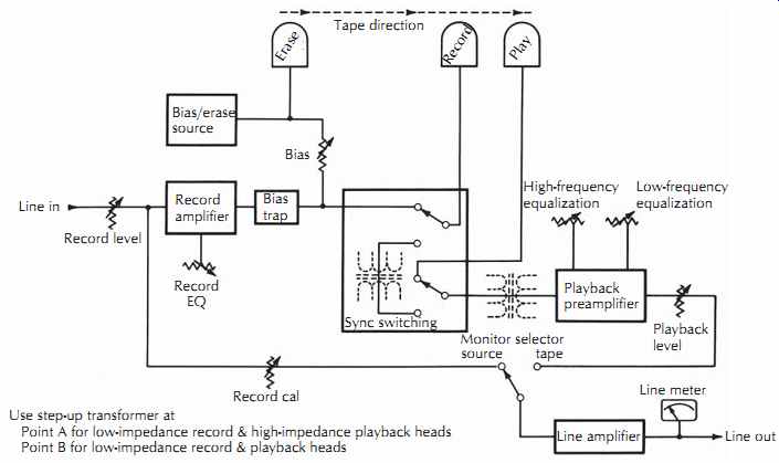
FIG. 36. Tape recorder signal block diagram.
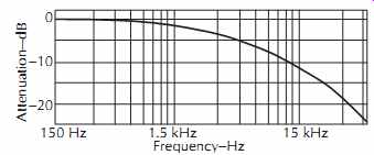
FIG. 37. Unequalized reproduce head output.
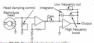
FIG. 38. Simplified playback amplifier.
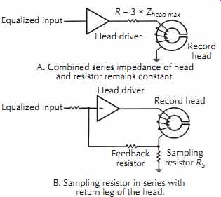
FIG. 39. Constant-current record head drivers.
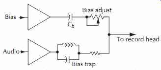
FIG. 40. Audio and bias coupling to record head.
4.2 Record Circuits
The primary task of the amplifier that drives the record head is to convert the input audio signal voltage into a proportional amount of current flowing in the windings of the record head. To accomplish this task, the head driver must overcome the rise in head impedance with frequency that is due to the inductance of the head. A common technique to achieve flat current response, as shown in FIG. 39A, is to insert a resistor in series with the head so that the combined series impedance of the resistor and the head remain relatively constant throughout the audio band. If the resistance is chosen to be two to three times the reactance of the head at the upper limit of the desired audio band, the desired constant current characteristics can be closely approximated.
The primary disadvantage of the series resistor is the loss of head room due to the extra signal drop across the resistor. This problem can be overcome with an active current feedback circuit that senses the current in the head through a small sampling resistor. FIG. 39B shows a sampling resistor Rs in series with the return leg of the head. The voltage generated across Rs by the current flowing in the head is fed back to the inverting input for comparison with the incoming audio signal.
The high gain of the driver amplifier necessitates only a very small feedback signal, creating a negligible loss in head room at high frequencies.
The circuits of FIG. 39 oversimplify the task of driving the record head since no provisions are included for adding the high-frequency bias signal to the current in the head. A common method of adding the bias and audio signals is shown in FIG. 40. The audio driver is isolated from the bias source by a parallel trap tuned to the bias frequency so that the bias signal does not create nonlinearities within the audio driver. The high impedance of the trap at the bias frequency also reduces the loading effect of the audio source on the bias source.
A similar isolation of the bias source is accomplished by the capacitor in series with the bias supply.
Since the capacitor looks like a high impedance at audio frequencies, the loading effect of the bias supply on the audio source is minimized. At the higher frequencies of the bias signal, the reactance of the capacitor has dropped to a relatively low value that provides adequate coupling of the bias signal into the record head.
An alternate approach that eliminates some of the previously mentioned isolation requirements is shown in FIG. 41. In this case, the bias and the audio are added together at the input to a combination bias/audio head driver amplifier. If the amplifier has sufficient head room and very low distortion, the two signals can be amplified simultaneously by the same amplifier without any interference. The problem of coupling the output to the head for constant current drive must still be overcome, however, by including either a complex coupling network or an active feedback network.
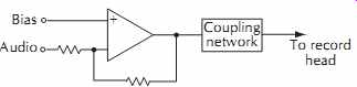
FIG. 41. Active summer for bias and audio.
In addition to the head driver circuits, which correct for any response droop due to head inductance, the record amplifier must provide deliberate frequency response tailoring to match the desired equalization standards. The standards usually require an adjustable boost at 6 dB/octave beginning in the middle of the audio band, with lower tape speeds generally requiring greater boosts to overcome the increased tape thickness and self-erasure losses.
The needed boost is easily implemented by the resistance-capacitance circuit shown in FIG. 42A, but the use of a variable capacitor is inconvenient due to the limited range of capacitor adjustment and the awkward size and mounting of the capacitor. Newer designs, therefore, favor operational amplifier configurations that control the amount of boost with a potentiometer.
One such circuit, shown in FIG. 42B, selectively adds the output of a differentiator circuit, which rises at 6 dB/octave, to the main signal path.
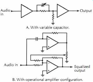
FIG. 42. High-frequency record boost circuits. A. With variable capacitor.
B. With operational amplifier configuration.
A secondary benefit of the differentiator circuit is the phase change introduced by the inverting characteristics of the differentiator amplifier. Unlike most of the loss-correction circuits of the signal path, which intro duce signal delay at high frequencies, the inverted differentiator advances the high frequencies. The proper combination of advance and delay can provide less phase distortion in the signal, yielding improved transient response with less overshoot. A similar phase-correcting effect has been implemented in other designs by providing an all-pass, phase-shifting network in the reproduce amplifier.
The NAB and compact cassette equalization standards provide an additional record signal boost at low frequencies to overcome the hum and noise limitations of the reproduce heads and amplifiers. Typical circuits for this purpose are shown in FIG. 43. Both cases achieve a 6 dB/octave rise with decreasing frequency from 50 Hz or 100 Hz to below 20 Hz.
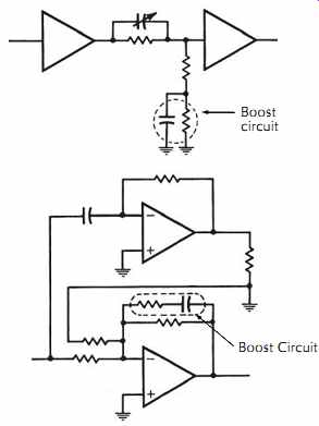
FIG. 43. Low-frequency record boost circuits.
Abrupt changes in the bias and audio signals on the record head must be avoided whenever the record mode is entered or exited. Ramping circuits are employed for this purpose to control the buildup and decay of these signals. Typical methods include the use of analog switching elements such as bipolar-junction or field-effect transistors. The rate of switching of these elements is limited to a value that does not create abrupt transients but, at the same time, is quick enough to avoid annoying delays, over-recordings, or program holes.
4.3 Bias and Erase Circuits
The high-frequency signals required for biasing and erasing all tracks of the tape are derived from a single master oscillator so that no interference or beating of multiple oscillators will occur. Older designs generally employ a tuned push-pull multivibrator oscillator; newer designs favor crystal-stabilized oscillators utilizing digital circuitry. Several designs have used separate bias and erase frequencies, with the erase circuit running at one-third the bias frequency to minimize the power dissipation on the erase head.
In all cases, the primary consideration is purity of the bias and erase current waveforms. Any even-order harmonics, including dc, second harmonics, fourth harmonics, and so on, will create a detrimental rise in the background tape noise, reducing the available SNR for the recorder. Older designs, such as FIG. 44A, relied heavily on push-pull circuits with balancing transformers to minimize these even-order components.
Newer designs, such as FIG. 44B, favor filtering and feedback control to reduce unwanted components. The divide-by-two flip-flop eliminates any even-order distortion in the oscillator waveform.
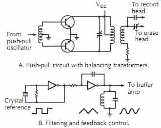
FIG. 44. Typical bias and erase sources. B. Filtering and feedback control.
A. Push-pull circuit with balancing transformers.
The erase head is typically coupled to the erase source with an adjustable series resonating capacitor to minimize the voltage required from the driver and to filter out even-order components. A current sampling resistor is frequently provided in the ground leg of the erase head circuit so that the amplitude of the erase current can be conveniently monitored.
4.4 Noise Reduction Systems
The SNR of an analog audio recorder is usually taken as the difference between the residual biased tape noise level and the level which produces 3% third harmonic distortion at 1 kHz. In the ideal case this ratio is limited by the tape speed, track width, and tape type. Once these parameters are set, the maximum SNR is determined.
Direct analog noise reduction systems rely on the masking effect of human hearing. If both a background noise and a louder desired signal exist within the same frequency band, the noise will be masked by the desired signal. If, on the other hand, the noise and signals are in different parts of the audio spectrum, such as a bass guitar and high-frequency tape hiss, the noise will not be masked. The perceived noise can be reduced if the SNR is compromised during masking situations so that unmasked noise can be reduced. This requires dynamic change of the gain or transfer function of the system depending on the program content.
Dolby and dbx noise reduction systems are examples of amplitude-only encode/decode systems.
Both systems modify the amplitude of the signal to squeeze the dynamic range of the input signal into a smaller dynamic range that will avoid the noise and distortion limitations of the recording tape. The fidelity of these compander (compression/expander) systems is limited not only by the tracking of the encode and decode circuits, but also by the nature of the errors that are generated by noise, nonlinearities, and frequency response anomalies introduced by the record/playback cycle of the tape recorder. These parasitic errors can cause dynamic mistracking that will create distortions of dynamic signals that may not be evident during sine-wave testing.
The Dolby systems process the low-level signals by boosting them during recording and then attenuating them on playback. The original professional Dolby system (Dolby A) subdivides the audio spectrum into bands that are processed individually to optimize the masking effect.
A later development, the Dolby SR system also adds adaptive filters that change their cutoff frequencies as the signal content varies. When the program material includes information at high frequencies, the filter opens up to full bandwidth. If no high-frequency content is present, the cutoff frequency of the filter slides down to match the program material. The filter must be "intelligent" enough to distinguish between desired audio signals and unwanted noise.
The Dolby SR system was quickly embraced by the music and film markets as a method of raising analog recorder performance to a level that rivals digital recorders.
DBX is also a "compander" system, but instead of dividing the spectrum into bands and acting on each band differently, DBX acted on the true RMS value of the signal. This resulted in SNR improvements that were significantly better than Dolby A, but many users felt that the DBX system was more prone to audible artifacts of the process.
4.5 Sync Operation
Multitrack recording requires that artists be able to listen to the previously recorded tracks while simultaneously adding their new performance in synchronism with the prior tracks. Analog recorders accomplish this by using some tracks of the record head as playback sources while simultaneously recording on other tracks of the same head.