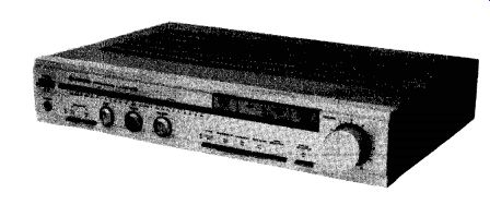
THE Hitachi HA-4700 integrated amplifier is rated to deliver 50 watts per channel to 8-ohm loads from 20 to 20,000 Hz with no more than 0.02 percent total harmonic distortion. It employs a "super-linear" output circuit similar to those used in some other amplifiers to reduce crossover distortion without sacrificing the efficiency of class-AB amplification. The bias on the output transistors is varied dynamically ac cording to the signal level to shift their operating characteristics from class-A at low levels to class-AB at higher outputs.
The HA-4700's phono preamplifier can be switched for use with either moving-magnet (MM) or moving-coil (MC) cartridges. The program source is selected by a row of flat buttons with colored lights below them showing which has been selected. The inputs are identified as PHONO, AUX, TUNER, and TAPE (the last can be operated independently of the others for listening to a tax recorder's playback regardless of the regular program source).
On the same horizontal line with the input-source lights are two horizontal rows of LEDs that display the instantaneous power output of each channel (based on 8-ohm loads). The lights are calibrated from 0.04 to 100 watts (- 31 to +3 dB referred to the rated 50 watts output). Green LEDs are used up to 50 watts, red ones at higher power levels.
Below the power indicators are three knobs, protruding only slightly from the panel, for the bass, treble, and balance controls. There is a large volume knob at the right of the panel, and all the other controls are pushbuttons. The illuminated power switch and the headphone jack are at the left of the panel near the two speaker switches. Below the input selectors are narrow rectangular buttons for the TONE DE FEAT. SUBSONIC FIL (filter), LOUDNESS. TAPE COPY (from deck 1 to deck 2 only), TAPE SELECTOR (for playback from either deck when the input tape button is engaged), and PHONO SELECTOR for MM or MC phono cartridges.
On the rear of the Hitachi HA-4700 are the usual phono-jack inputs and outputs, insulated spring connectors for the speaker outputs, and three a.c. outlets, two of them switched. The amplifier is finished in satin silver and measures 17 1/4 inches wide, 12 7/8 inches deep, and 3 1/4 inches high. Weight is about 133/4 pounds. Price: $299.95.
Laboratory Measurements. After an hour's operation at one-third rated power the top of the HA-4700 (over the enclosed power-transistor heat-dissipating fins) was uncomfortably hot to the touch, but it never became more than mildly warm in normal operation.
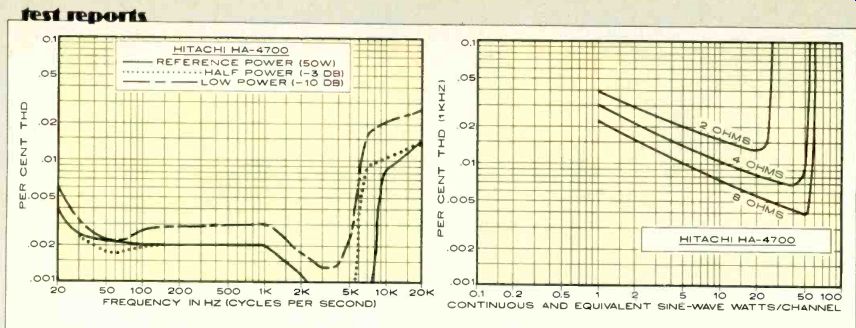
--------- HITACHI HA-4700; POWER REFERENCE (50W) HALF POWER (-3 DB); --LOW
POWER (-10 DB); FREQUENCY IN HZ (CYCLES PER SECOND) CONTINUOUS AND EQUIVALENT
SINE-WAVE WATTS/CHANNEL
When we drove both channels at 1,000 Hz into 8-ohm loads, the output waveform clipped at 60.5 watts for an IHF clipping-headroom rating of 0.83 dB. The amplifier is not rated for use with lower load impedances, but we measured clipping outputs into 4 and 2 ohms of 54.8 and 25.2 watts, respectively. The IHF dynamic headroom (8 ohms) was a very good 2.58 dB, corresponding to a maximum short-term output of 90.6 watts. Into 4 and 2 ohms the dynamic power output was 60 and 29.7 watts, respectively.
For a reference output of 1 watt into 8 ohms, the HA-4700 required an input into the AL x jack of 24 millivolts (mV), 0.32 mV into the PHONO (MM) jack. The respective A-weighted noise levels were -83 and -81 dB referred to 1 watt (both very good readings for an integrated amplifier). The phono-preamplifier stage overloaded at a high 230-mV input at 1,000 Hz, and the equivalent overload limits at 20 and 20,000 Hz were 250 and 152 mV. The phono-input impedance was 46,000 ohms in parallel with 250 picofarads. Although we made no measurements with the MC input, its gain is about seventeen times higher than the MM input (+24 dB), and it terminates the cartridge in 100 ohms.
The harmonic distortion of the Hitachi HA-4700 was extremely low. With 8-ohm loads, the distortion at 1,000 Hz was between 0.004 and 0.008 per cent from I to 50 watts output, reaching the rated 0.02 per cent at 60 watts just as clipping was beginning. The performance into 4-ohm loads was generally similar, with distortion readings falling from 0.03 percent at 1 watt to well under 0.01 percent between 20 and 50 watts and rising to 0.08 per cent at 55 watts.
The amplifier's output-current limitations prevented it from delivering much power to 2-ohm loads, and its distortion was in :he range of 0.015 to 0.04 percent for outputs up to 25 watts. The two-tone intermodulation-distortion measurement with equal amplitude signals at 19 and 20 kHz revealed no detectable second-order distortion (1,000 Hz) and a barely detectable third-order product (18kHz) at -92 dB referred to the rated 50-watt output of the amplifier. The slew factor was greater than 25, and the amplifier rise time was 4 micro seconds. The overload-recovery time (from a 10-dB overdrive condition) was a negligible 5 microseconds, and the amplifier was stable with simulated complex reactive speaker loads.
The distortion at rated power output was no more than 0.002 to 0.008 per cent over most of the audible frequency range, reaching a maximum of 0.015 percent at 20,000 Hz and falling to a nearly unmeasurable 0.0007 percent from 3,000 to 7,000 Hz. At half and one-tenth power the shape of the distortion curve was similar, with only slightly higher readings.
The tone controls had a sliding bass-turn over frequency (from about 100 to 500 Hz) and treble curves hinged at 2,000 to 3,000 Hz. The maximum bass boost occurred in the range from 50 to 100 Hz. The loudness compensation boosted both low and high frequencies, but only moderately. The "subsonic" filter appeared to have only a 6-dB-per-octave slope, with its-3-dB response at 60 Hz and-10 dB at 20 Hz. The RIAA phono equalization was accurate within ±0.25 dB from 20 to 20,000 Hz, and the inductance of most cartridges caused no more than a 0.5-dB rise in the output be tween 10,000 and 20,000 Hz.
Comment.
The Hitachi HA-4700, although appearing with relatively little fanfare or publicity, has most of the features that have been seen of late in the top amplifiers of many other manufacturers. It is a compact, handsomely styled, and versatile amplifier that sounds as good as it measures. No manner of sonic flaws or operating "glitches" showed up in our testing or listening to the amplifier, and we came away with a thoroughly positive impression of its performance and overall design.
The HA-4700 has a very comprehensive protection system that manages to be completely unobtrusive as well as effective. A short circuit across the outputs will shut down the amplifier if it is driven hard, and the power must be switched off for a few seconds to restore it to service. Although a d.c.-offset voltage at the output will also silence the amplifier, it recovers from that automatically when the fault is removed.
There is also a thermal cut-out that shuts the HA-4700 off if it becomes too hot. None of these protective systems operated during our tests, in spite of their severity, but it was reassuring to know they were there and waiting if need for them arose.
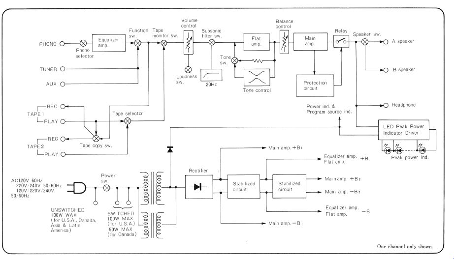
The schematic of this HA-4700 amplifier (pre-amp section) revealed a feature whose presence we would not have suspected from our measurements. A major problem of modern hi-fi systems is their susceptibility to interference from strong radio-frequency fields from nearby transmitters. Often these signals enter through the phono leads, overloading the low-level stages and superimposing the modulation of the r.f. signal on the regular program (or even completely obliterating the program). External filters are a possible treatment for this condition, but their success is uncertain, and there is also the possibility of de grading the amplifier's frequency response by an improper cartridge termination. Hitachi has built an L-C low-pass filter into the HA-4700 at the phono input. We calculate that the filter has a cut-off frequency of about 1.5 MHz, which should help in cases of interference from nearby CB or amateur radio stations, although it probably will not do much if one is unfortunate enough to live in the shadow of a powerful AM broadcast station. So far as we can see, the only sacrifice made for this feature is the relatively high 250-pF input capacitance of the phono section, but this should not cause problems with most combinations of record player and cartridge. [Note: a tweak to improve the phono section mau include elimination of this filter; and simply enclose the amp in a grounded metal cabinet.]
The Hitachi HA-4700 is, therefore, a thoroughly up-to-date, very high-quality, moderate-power integrated amplifier selling at a most modest price. It is an excellent value in every way.
+++++++ BONUS!! ++++++++
Owner's Manual (below)
STEREO AMPLIFIER INSTRUCTION MANUAL
Congratulations! HITACHI Hi-Fi products are the proud result of HITACHI engineering research and development and over 70 years of experience in electronics. Laboratories and major testing facilities are maintained in Tokyo and Toyokawa, Japan.
In choosing this fine HITACHI Hi-Fi product you have demonstrated an acute awareness of 'getting the best for your money". With HITACHI products this is not an idle boast.
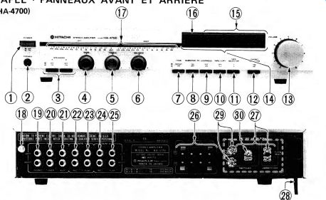
KEY TO ILLUSTRATIONS
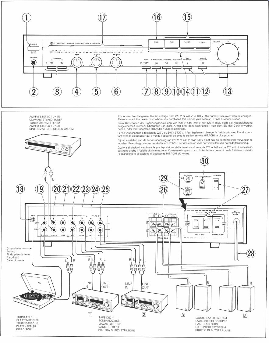
(1) POWER switch (- PHONES jack (- SPEAKERS switches
- BASS control (- TREBLE control
- BALANCE control
- TONE switch (- SUBSONIC-FILTER switch (- LOUDNESS switch 10 TAPE COPY switch
- TAPE SELECTOR switch PHONO SELECTOR switch
- VOLUME control
- Program source indicators FUNCTION switches
-- TAPE monitor switch Peak indicate peak power indicators
(18 Ground terminal (GND) A9PHONO INPUT terminals QO TUNER INPUT terminals
-)AUX INPUT terminals
-TAPE-1 REC terminals
-TAPE-1 PLAY terminals
- TAPE-2 REC terminals
-TAPE-2 PLAY terminals 20 SPEAKERS terminals
-) AC outlet (3 outlets for U.S.A. and Canadian sets, 1 outlet for Asian and Latin American countries sets.)
- Power supply cord
-FUSE holder (for Asian and Latin American countries) VOLTAGE SELECTOR (for Asian and Latin American countries)
SAFEGUARD
Electrical energy can perform many useful functions. This unit has been engineered and manufactured to assure your personal safety. Improper use can result in potential electrical shock or fire hazards. In order not to defeat the safeguards, observe the following instructions for its installation, use and servicing.
INSTALLATION
Please bear in mind the following points when installing the HA-4700.
1. Install it in a place free from direct sunlight and heat from a stove, etc.
2. Since the HA-4700 incorporates a large power output amplifier, choose a well ventilated, moisture-free place.
3. Install the amplifier on a stable and vibration-free surface.
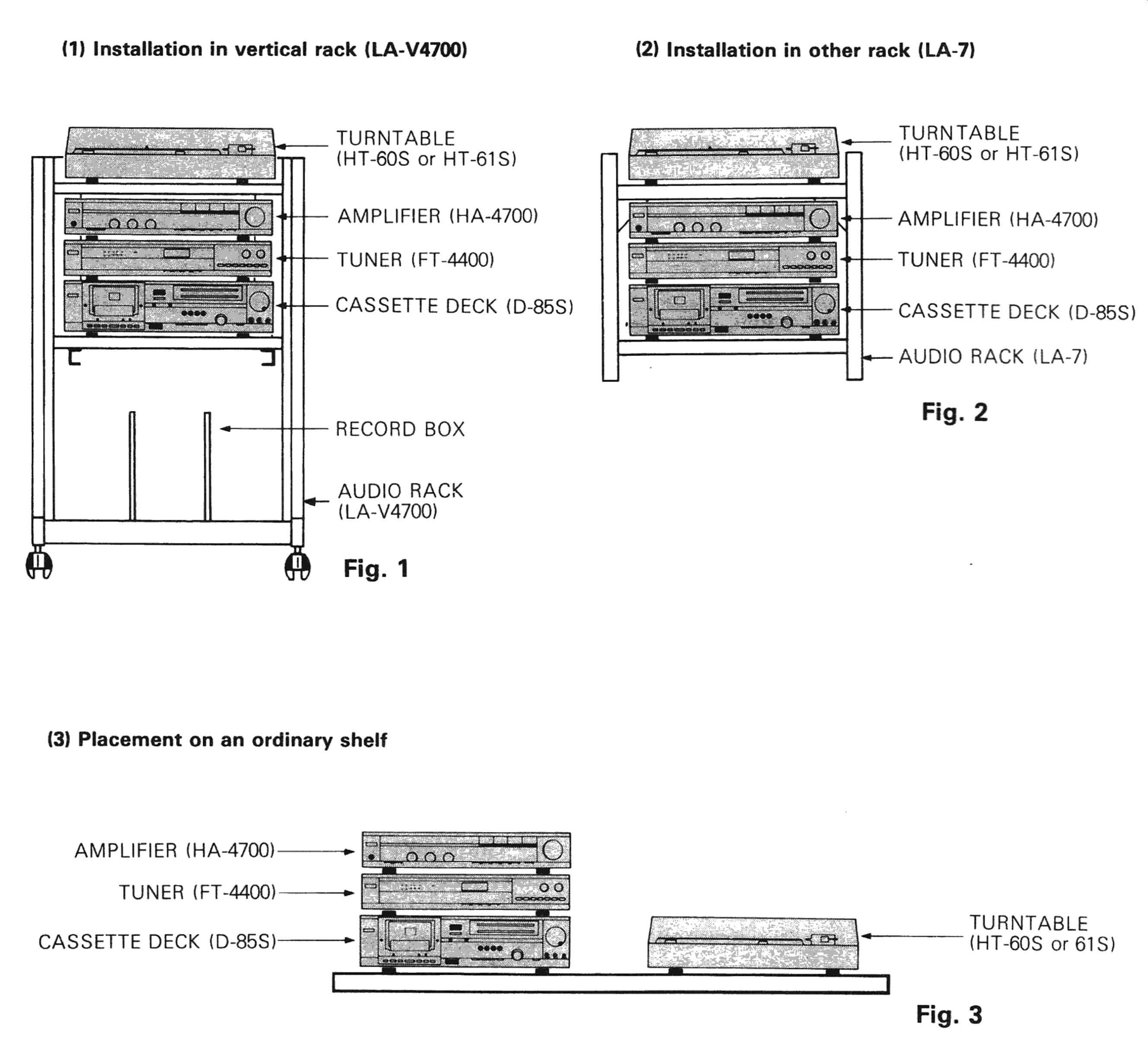
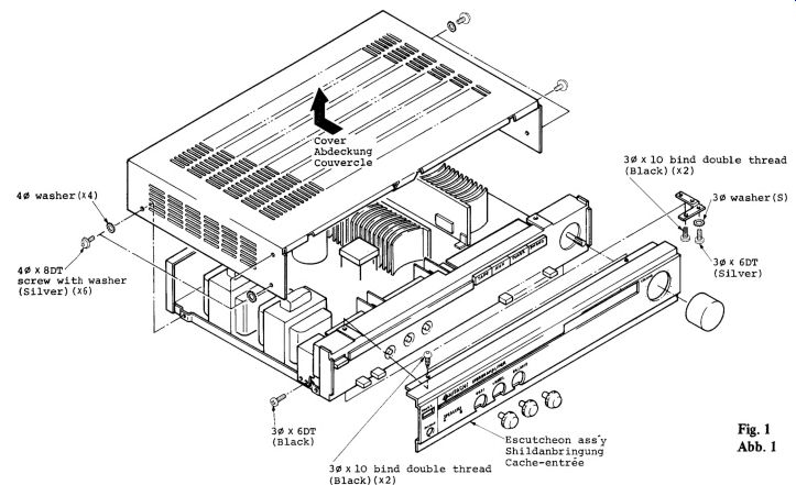
4. The installations indicated in Figs. 1, 2 and 3 are recommended, and audio racks, HA-4700 or LA-7 are recommended.
NOTE:
* Even when using an audio rack which is not designated, be sure to leave spaces around the components to allow the heat to dissipate, and make sure that the amplifier and tuner are separated by a shelf.
Even when an audio rack is not used, it is recommended that the amplifier be placed above the tuner in order to allow the heat to escape efficiently.
(1) Installation in vertical rack (LA-V4700) TURNTABLE (HT-60S or HT-61S) AMPLIFIER (HA-4700) TUNER (FT-4400) CASSETTE DECK (D-85S) RECORD BOX AUDIO RACK (LA-V4700) Fig. 1
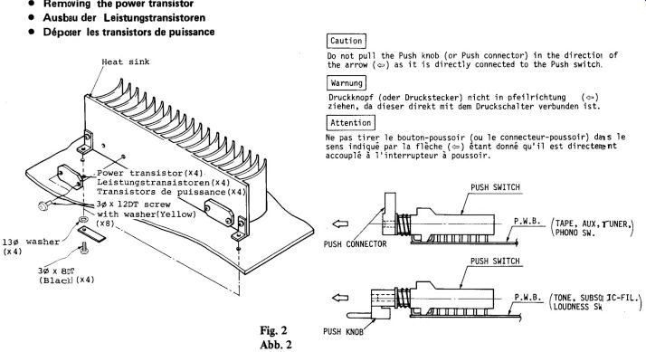
(2) Installation in other rack (LA-7) TURNTABLE (HT-60S or HT-61S) AMPLIFIER (HA-4700) TUNER (FT-4400) CASSETTE DECK (D-85S) AUDIO RACK (LA-7) Fig. 2
(3) Placement on an ordinary shelf AMPLIFIER (HA-4700) Bare TUNER (FT-4400) -- [FET TURNTABLE
=H (HT-60S or 61S) CASSETTE DECK (D-85S) Fig. 3
IMPORTANT FOR U.K.:
The wires in this mains lead are colored in accordance with the following code:
Blue: NEUTRAL Brown: LIVE As the colors of the wires in the mains lead of this apparatus may not correspond with the colored ...IMPORTANT NOTICES (1 (2) (3) When measuring the power output or listening to program sources with a 4 ohm load impedance, do not drive the Model HA-4700 at a level where the peak power indicator indicates 40 W or more for a long period of time.
A tape deck being used may be susceptible to induction from the amplifier, although this depends on the type of tape deck, and there may be a hum sound. In such cases, install the tape deck in a location where it will not be susceptible to the induction. (For instance, place the tape deck on the right of the amplifier when viewed from the front.) Do not place the tape deck on the amplifier since this will impair the amplifier performance.
Hum may be induced if other audio components are brought near the unit. In cases like this, increase the distance between the unit and the other components, rearrange their positions and make sure that the hum is not generated.
CAUTIONS
1. Turntable and tape deck connections Be sure to use thick shielded cables with low stray capacitance for connection. If a parallel vinyl cord or a thin shielded cable is used, inductive hum may be produced and the high-range frequency characteristics will deteriorate considerably.
Therefore, it is recommended that you use thick and short cables if available.
. Protection circuit Set the POWER switch (1)to ON. The sound is heard within 6- 10 sec. If the sound is not heard after 6- 10 sec. or the protection circuit starts operation immediately, turn the POWER switch(1)to OFF, and check whether the speakers are properly connected and whether the speaker terminals or speaker leads have been short-circuited. Then eliminate the cause of trouble, set the POWER switch (1) to ON again after waiting for about 10 sec. with the POWER switch (1)at OFF. If the set still does not work, contact the dealer from whom you purchased this unit or your nearest HITACHI service station.
. Amplifier heat loss A large power output amplifier radiates heat. Although ventilation holes are provided in the upper part of the case and the bottom plate to improve heat dissipation, placing this amplifier in direct sunlight or placing anything directly on the amplifier may interfere with this ventilation and malfunctions may occur. If the internal temperature rises, the transistors may be damaged. Take care not to block the ventilation holes.
FEATURES
1. Wide-band, low-distortion design for best sound quality The power amplifier section adopts a super linear circuit with power transistors featuring an excellent frequency response and a high transition frequency. Its design is aimed at reducing the deviations in the phase that adversely affect the sound quality and also the generation of switching distortion by the power transistors. As a result, a distortion of only 0.02% is yielded with an effective power output of 50 Watts + 50 Watts (at 8 ohms, 20 Hz to 20 kHz).
. Equalizer circuit with high sensitivity and S/N ratio The equalizer circuit features a combination of newly developed low-noise transistors and low-noise ICs to produce a high sensitivity of 0.156 mV (MC), making it possible to use a moving coil (MC) phono-cartridge without a head amplifier. The same circuit yields a high signal-to-noise ratio of 90 dB (MM) and 73 dB (MC), and so even weak signals are clearly reproduced.
. 24-LED power indication There are two peak power meters, one for the left channel and the other for the right, and they both employ twelve LEDs. They show the power with good rise character istics in tune with the fluctuations in the music signals.
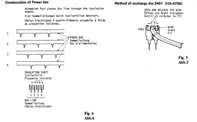
. Power supply section with a powerful punch The two power transformers, the large capacity smoothing capacitors (8,200 uF + 8,200 uF) and the newly developed power bus line (which uses oxygen-free copper) all combine to reduce the deterioration in the distortion caused by interaction up to high power output levels.
. Highly reliable protection circuit This unit contains a protection circuit con figured with a monolithic IC and a power relay, and so in the unlikely event of trouble, it protects both the speakers and the output transistors. Furthermore, the IC has a built in muting circuit which reduces the shock noise caused when the power switch is set to the ON and OFF positions.
. Connection facilities for two tape decks The unit has connection facilities for two tape decks to enable tape dubbing and recording of a broadcast or record on one deck while a tape is playing back on the other deck.
. Connection facilities for two pairs of" speakers Two pairs of speakers can be hooked up to the unit, and by switching between them, it is possible to compare the sound. The sound can also be heard simultaneously through both pairs.
. Sleek and chic design With its self-illuminating power switch and its function selectors which combine pro gram source indicators with a wide look, and light-touch-controlled push button switches, the control section looks both sleek and chic and it has an air of distinction.
CONTROLS AND SWITCHES (1) POWER switch When this switch is set to ON (22) power is supplied to the amplifier. The HA-4700 contains a muting relay and so it takes about 6 - 10 seconds after this switch has been set to ON (2) for the amplifier to operate normally.
2) PHONES jack Insert the plug on the stereo headphones in to this jack. If you want to listen with the headphones only, set the SPEAKERS switches (3) to OFF.
(3 SPEAKERS switches OFF (O) ......... No sound can be heard from the speakers. Use headphones for listening. For listening to the sound both through the speakers and with the head phones, set these switches to ON (=).
AON (2) ....... The sound can be heard through the speakers which are connected to the A speaker terminals.
B:ON (=) ....... The sound can be heard through the speakers which are connected to the B speaker terminals.
A:ON (2) B:ON (4) ....... The sound can be heard through the speakers which are connected to both A and B speaker terminals.
NOTE:
When 4 ohm speakers are connected to both A and B speaker terminals, and the SPEAKERS switches (3) are set at ON, the combined impedance of the speakers is only 2 ohms. Avoid using this arrangement. Be sure to connect speakers of more than 8 ohms when two sets of speakers are to be operated simultaneously.
(4) BASS control Turning this control to the right from the "CENTER" position increases the bass, and turning it to the left decreases the bass.
(5 TREBLE control Turning this control to the right from the "CENTER" position increases the treble, and turning it to the left decreases the treble.
(6) BALANCE control This adjusts the balance of right and left channel levels.
(I) TONE switch Set this switch to ON (21) when you want to control the tone characteristics, and then proceed with the BASS -) and TREBLE (- controls. Setting this switch to the DEFEAT (0) position yields a flat frequency response irrespective of the BASS (3) and TREBLE (- controls.
(8)SUBSONIC-FILTER switch This switch makes it possible to cut out low frequency noise such as the harmful effects of subsonic frequencies produced by warped records.
(9 LOUDNESS switch Due to the characteristics of the human ear, the bass and treble seem to drop off when the sound volume is decreased. In order to compensate for this, push this switch to ON (22), and the bass and treble will then be emphasized by +6 dB at 100 Hz and +4 dB at 10 kHz respectively.
10 TAPE COPY switch OFF (Od) ......... With the switch in this position it is possible to record the incoming program source (broadcast or record, etc.) simultaneously onto the tape decks connected to tape deck terminals 1 and 2.
1D>2(3)....... The tape in the tape deck connected to tape deck terminals 1 can be played and the sound recorded (tape copying or dubbing) onto a tape in the tape deck connected to tape deck terminals 2.
This operation can be performed simultaneously when another program source (such as a broadcast) is being heard.
At this position, however, it is not possible to record the program source.
ID TAPE SELECTOR switch 100) oe, Set to the released position when playing back a tape in the tape deck connected to tape deck terminals 1 or when monitoring the tape sound (refer to "Tape monitoring" on the next page).
0 = Set to the depressed position when playing back a tape in the tape deck connected to tape deck terminals 2 or when monitoring the tape sound.
(2 PHONO SELECTOR switch This is selected in line with the type of phono-cartridge, MM or MC, on the turn table.
MM (0) ......... Release when using a moving magnet (MM) cartridge.
ME (8) sus ms
Depress when using a moving coil (MC) cartridge.
(13 VOLUME control Use this to adjust the sound volume.
Set the VOLUME control to its leftmost position ('0') when switching the power on and off in order to protect the speakers.
(9 Program source indicators These indicators go on in accordance with program source.
(9 FUNCTION switches These switches select the program source.
PHONO ......... For listening to a record on a turntable connected to the PHONO INPUT terminals(9.
TUNER .......... For listening to a broadcast on a tuner connected to the TUNER INPUT terminals -0.
AUX For listening to a program source on a component connected to the AUX INPUT terminals.
TAPE monitor switch Set this switch to the depressed position (see "Tape monitoring' on page 6) when monitoring the tape sound or playing back a tape. The indicator below the switch will then light. To release the switch, simply depress it again. The indicator will then go off to show that the switch has been released (OFF position).
(Select the tape deck which is being used with the tape selector-D.)
(7 Peak power indicators Twelve LEDs for each channel light up to show the power output.
NOTE:
When the impedance of the speakers is 8 ohms, the level of the indicators expresses the power output in watts. When the impedance of the speakers is only 4 ohms, the actual output is double the value indicated by the indicators.
---------------
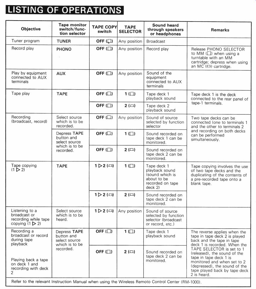
LISTING OF OPERATIONS
Tape monitor switch/function selector TAPE COPY Tuner program Record play
Play by equipment connected to AUX terminals Tape play Recording (broadcast, record) Select source which is to be recorded.
Depress TAPE button and select source which is to be recorded.
Tape copying 1D>2 Select source which is to be heard.
Listening to a broadcast or recording while tape copying (1 [> 2) Recording a broadcast or record during tape playback Depress TAPE button and select source which is to be recorded.
Playing back a tape on deck 1 and recording with deck 2 Sound heard TAPE through speakers SELECTOR or headphones Any position | Record play Any position | Sound of the equipment connected to AUX terminals Tape deck 2 playback sound Release PHONO SELECTOR to MM (1) when using a turntable with an MM cartridge; depress when using an MC (3) cartridge.
Tape deck 1 is the deck connected to the rear panel of tape-1 terminals.
Sound of source selected by function selector Any position Sound recorded on tape deck 1 can be monitored.
Sound recorded on tape deck 2 can be monitored.
Tape deck 1 playback sound (sound which is about to be recorded on tape deck 2) Sound recorded on tape deck 2 can be monitored.
Two tape decks can be connected (one to terminals 1 and the other to terminals 2 and recording on both decks can be performed simultaneously.
Tape copying involves the use of two tape decks and the duplicating of the contents of a pre-recorded tape onto a blank tape.
Any position | Sound of source selected by function selector (broadcast or record, etc.) Tape deck 1 playback sound
Sound recorded on tape deck 2 can be monitored.
The reverse applies when the tape in tape deck 2 is played back and the tape in tape deck 1 is recorded. When the TAPE SELECTOR is set to 1 (released), the sound of the tape in tape deck 1 is monitored and when set to 2 (depressed), the sound of the tape played back by tape deck 2 is heard.
------------
Refer to the relevant Instruction Manual when using the Wireless Remote Control Center (RM-1000).
-----------------
NOTE TAPE and by switching the TAPE monitor switch (16) between the OFF and ON positions.
In this way, you can check the quality of your recording. This operation is known as tape monitoring. When the TAPE monitor switch is set to the OFF position, the sound which you are about to record is heard through the speakers. When set to the ON position, the sound which you have just recorded is now heard through the speakers as the monitor sound, enabling you to check the quality of the recording.
NOTE:
When recording while monitoring the sound, it is necessary to connect both the recording and the playback cords.
* Adjust the recording level with the recording level controls on the tape deck. When recording a broadcast or record, adjusting the unit's volume control or bass and treble controls has no effect on the sound which is recorded.
The material which you record may be used for your own personal entertainment as long as this use does not infringe the copyrights of third parties.
Tape monitoring If you use a 3-head (independent erase, record and playback heads) tape deck, you can com pare the sound you are about to record and the sound you have just recorded in an instant by keeping the monitor switch on the tape deck to
Precautions
- Turn the volume control to its leftmost position in order to protect the speakers when you change over records, when the cartridge is lowered and raised, and when you switch the power on and off.
If you move the tone controls or the switch immediately (within 10 seconds) after you have set the power switch to ON, noise may be heard through the speakers or headphones. This does not indicate a failure.
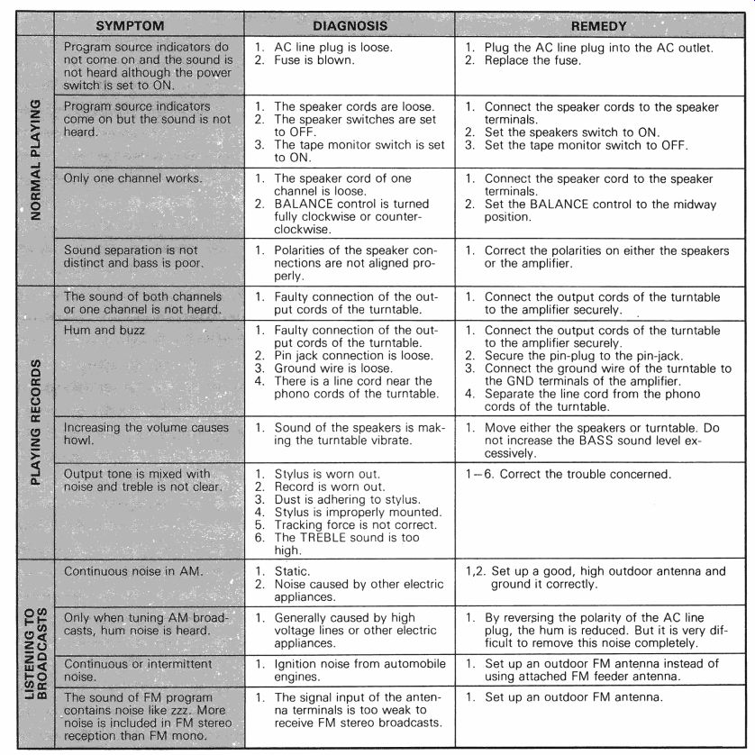
WHAT TO DO IF?
A variety of problems may result from the mishandling of the amplifier.
When a problem occurs, check the table below which describes possible problems occurring in your amplifier. Since the amplifier is completely checked and adjusted before shipping, there are no user serviceable and adjustable parts inside. But if the amplifier is not operating correctly and you are unable to restore normal operation by following the detailed procedure in the table below, do not remove the cover of the set or attempt any further adjustments. Unplug the set and contact your dealer or nearest HITACHI service station.
----------
. AC line plug is loose.
. Fuse is blown.
to OFF.
to ON.
NORMAL PLAYING clockwise.
1. Polarities of the speaker connections are not aligned properly.
. Faulty connection of the output cords of the turntable.
Pin jack connection is loose.
. Ground wire is loose.
. There is a line cord near the phono cords of the turntable.
: nc casing the volume causes g how. :
Output tone is mixed with noise and treble is not clear.
. The speaker cords are loose.
. The speaker switches are set
. The tape monitor switch is set
. The speaker cord of one channel is loose.
BALANCE control is turned fully clockwise or counter
Sound of the speakers is making the turntable vibrate.
. Stylus is worn out.
. Record is worn out.
Dust is adhering to stylus.
REMEDY Plug the AC line plug into the AC outlet
Replace the fuse.
. Connect the speaker cords to the speaker terminals.
. Set the speakers switch to ON.
. Set the tape monitor switch to OFF.
. Connect the speaker cord to the speaker terminals.
Set the BALANCE control to the midway position.
Correct the polarities on either the speakers or the amplifier.
Connect the output cords of the turntable to the amplifier securely.
2. Secure the pin-plug to the pin-jack.
3. Connect the ground wire of the turntable to the GND terminals of the amplifier.
4. Separate the line cord from the phono cords of the turntable.
Move either the speakers or turntable. Do not increase the BASS sound level excessively.
1-6. Correct the trouble concerned.
. Stylus is improperly mounted.
. Tracking force is not correct.
. The TREBLE sound is too high.
. Static.
. Noise caused by other electric appliances.
8 "Only when tuning AM broad. | 1.
| casts, hum noise is heard.
| appliances.
T Continuous or intermittent
LISTENING TO .
"noise is included in FM stereo
| reception than FM mono. =
Generally caused by high voltage lines or other electric 1,2. Set up a good, high outdoor antenna and ground it correctly.
1. By reversing the polarity of the AC line plug, the hum is reduced. But it is very difficult to remove this noise completely.
1. Ignition noise from automobile 1. Set up an outdoor FM antenna instead of engines. using attached FM feeder antenna.
The signal input of the antenna terminals is too weak to receive FM stereo broadcasts.
Set up an outdoor FM antenna.
---------------
SPECIFICATIONS
Power output (Both channels driven) Power bandwidth Frequency characteristics TUNER, TAPE 1, 2 PHONO Harmonic distortion (8 ohms) (at rated output) (at 1/2 rated output) Intermodulation distortion (at 1/2 rated output) Input sensitivity/ Impedance PHONO TUNER, AUX TAPE PLAY 1, 2 Output level TAPE REC OUT 1, 2 Phono overload level (at 1 kHz, T.H.D. 0.01%) Signal-to-noise ratio (IHF, A network) PHONO TUNER, AUX, TAPE 1, 2 Damping factor Bass control Treble control Loudness control Subsonic filter Semi-conductors Power supply Power consumption Dimensions 50 watts* per channel, min. RMS, at 8 ohms from 20 Hz to 20 kHz, with no more than 0.02% total harmonic distortion.
50 W/ch + 50 W/ch (8 ohms, 1 kHz, T.H.D. 0.02%) 50 W/ch + 50 W/ch (4 ohms, 1 kHz, T.H.D. 0.02%) 5 Hz - 70 kHz (8 ohms, 1/2 Rated T.H.D. 0.05%) 10 Hz - 70 kHz (+0.5, =3.0 dB) RIAA =0.5 dB Less than 0.02% Less than 0.02% Less than 0.03% MM2.5 mV (47 k-ohms) MC 0.15 mV (100 ohms) 150 mV/47 k-ohms 150 mV/47 k-ohms 160 mV 220 mV 90 dB (MM) 73 dB (MC, input level 0.25 mV) 105 dB 40 (1 kHz, 8 ohms)
+8 dB (100 Hz)
+8 dB (10 kHz)
+6 dB (100 Hz)
+4 dB (10 kHz)
20 Hz
5 ICs, 67 transistors and 71 diodes (24 LEDs)
AC 120 V 60 Hz, ~220 V 50/60 Hz, ~240 V 50/60 Hz or ~120 V/220 V/240 V 50/60 Hz 310 VA, 270 W (at 1/3 rated output) 430 W (at rated output) 435 (W) x 83 (H) x 326 (D) mm (for U.S.A. and Canada) 435 (W) x 83 (H) x 299 (D) mm (for Europe and Australia) 436 (W) x 83 (H) x 334 (D) mm (for Asia and Latin American countries) 6.3 kg., Weight 6.3 kg
* Measured pursuant to the Federal Trade Commission's Trade Regulation Rule on Power Output Claims for Amplifiers.
Specifications and designs may be changed without notice for improvement.
Please contact the dealer from whom you purchased this unit or your nearest HITACHI service station.
- Hitachi, Ltd. Tokyo Japan Head Office : 5-1, I-chome, Marunouchi, Chiyoda-ku, Tokyo, Japan Tel. : Tokyo (212) 1111 (80 lines) Cable Address : "HITACHY" TOKYO
+++++++++++++
Excerpts from HA4700/3700 serv. manual (below)
ADJUSTMENT
1. Idle current adjustment
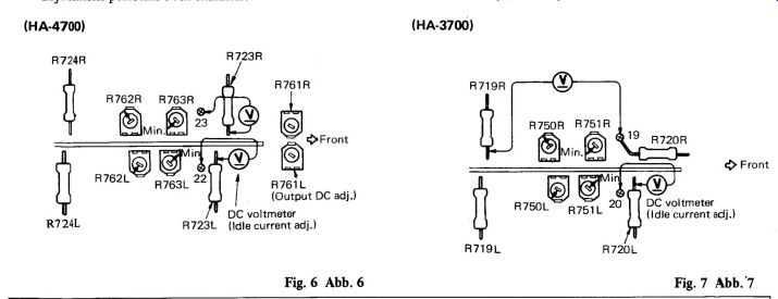
Set the unit to no signal, speaker select switch OFF, volume control minimum, R762L set to 1 - 2 o'clock
R762R, to 10 - 11 o'clock) and R763L(R) to minimum (counterclockwise). Next, connect a DC voltmeter o R723L(R) and test point 22(23) and turn the power switch ON . After more than 10 minutes later, perform he following adjustment to both channels.
Adjust R763L(R) so that the voltage is 7.7mV.
Next, adjust R762L(R) so that the voltage is minimum (7.7mV x 2mV).
When this is impossible, repeat Items (1) and (2). (Fig.6)
2. Output DC adjustment
Perform this adjustment with no signal, volume control minimum, speaker select switch set to A or B and with no load. Connect a DC voltmeter between (+) and S L(R) output terminals of speaker A or B and adjust R7611(R) shown in Fig. 6 so that the output DC is 0 within +- 20mV) measured in the 100mV range. This adjustment performs both channels.
HA-3700
Idle current adjustment
Set the unit to no signal, speaker select switch OFF, Volume control minimum, R750L to the 1 -2 o'clock position (750R, to the 10 - 11 o'clock position) and R7511L(R) to minimum (counterclockwise). Next, connect a DC voltmeter to R720L(R719R) and test point 20(19) and turn the power switch ON. After "more than 10 minutes, perform the following adjustment to both channels.
Adjust R751L(R) so that the voltage is 7.7mV.
Next, adjust R750L(R) so that the voltage is mini mum (7.7mV *2mV). When this is impossible, When this is impossible, repeat items (1) and (2). (Fig. 7)
Checking the super linear circuit
When the balance adjustment becomes impossible (when R762 <~HA4700 or R750 «<HA-3700 is adjusted, the minimum point of current disappears and only increase or attenuation is possible) during the idle current adjustment, this indicates trouble in the super linear circuit transistors (Q705-708) so check it. (HA-3700) R719R R750R
DC voltmeter
R761L R723L (idle current adj.) ( Output DC adj.) R724L
Fig. 6 Abb. 6 Cautions on repairing and replacing parts A4700/3700
Be careful that the measuring instrument does not touch he parts around the part to be adjusted by mistake when adjusting the idle current, etc. Carefully adjust idle current, etc. using an adjusting screwdriver insulated with tape, etc.
Care has been taken in use of such parts as using fuse resistors, floating installation, etc. to improve safety.
Be sure to use specified parts when replacing parts and install in the original condition.
if a measuring instrument with low impedance such as the tester is used when measuring the voltage of the first-stage transistors (Q701 - 703) of the main amp, ES DC voltmeter (Idle current adj.) R719L
Fig. 7 Abb.7
(1) The output DC adjustment may be changed when the parts of the stabilized power circuit or the main amp. are replaced. Be sure to check the output DC voltage.
(2) Check Q803 and Q804 when the +B voltage is not present. This circuit operates to accelerate the decay characteristics to the stabilized power circuit of the +B power supply when the power is switched OFF.
(3) 2 power transformers are used in this unit. When the thermal fuse of the power transformer or the primary fuse is blown, the bias of the transistors Q701 - 703 disappears and the amp. does not operate.
HA-4700 /3700
Caution on assembly Be careful in layout during installation of the switch PW before. installing the switch PW Board.
Board to the sub panel so that the 8-core jumper leads (3) Match the marking side (colored side) of the lead and does not touch the input selector switch. ~ mark wv stamped on the PW Board when installing the Install the PHONO selector switch to the sub panel 7-core/8-core jumper leads to the jumper socket.
HITACHI HA-4700/3700
DESCRIPTION OF THE NEW CIRCUIT
HA-4700/3700
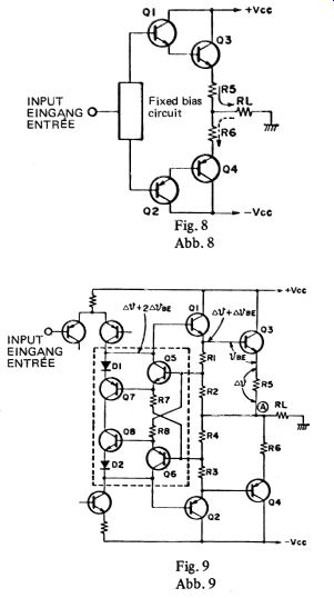
Super linear circuit
The class B amplifier circuit is constructed as shown in Fig. 8. A constant idle current flows from the fixed bias circuit, Q3 and Q4 are alternately switched ON/ OFF corresponding to the input signal, and current flows to Load Ry. However, with this transistor, the response of the output current is delayed with respect to the base input current due to the time of the carrier storage at the base when this transistor changed from OFF to ON. As a result, it causes generation of switching distortion when the transistor changes from OFF to ON; the frequency increases as the signal frequency is higher.
So, a circuit which varies the conventionally fixed bias voltage according to the signal strength applies a constant bias voltage when there is no signal to prevent Q3 and Q4 from being set to OFF and prevent the generation of switching distortion has been installed.
The circuit surrounded by broken lines in Fig. 9 shows this bias circuit; this is called the super linear circuit.
In Fig. 9, the output neutral point (A) with non-signal is assumed to be the reference. When a positive signal is input, positive current flows to the load resistor Ry.
Voltage drop Ay occurs in RS and Ay gg, in Q3 by means of this current, the emitter (Base of Q3) voltage of Q1 becomes higher by Av + Ay gg compared with that during no signal and the base bias of Q5 becomes higher. When the base bias of Q5 becomes higher, the current increases, the voltage across R7 becomes higher, and the bias voltage of Q6 does not change compared with that of point (A). Accordingly, the base voltage of Q2 which is biased by Q6, Q8 and D2 is kept approximately the same as that during no signal, and the idle current continues to flow.
In the case of a negative signal, the reverse operation is performed keeping the base bias of Q1 constant. In the actual circuit, variable resistors are used for R2, R4 to adjust idle current, and in addition, a circuit which performs thermal compensation is installed.
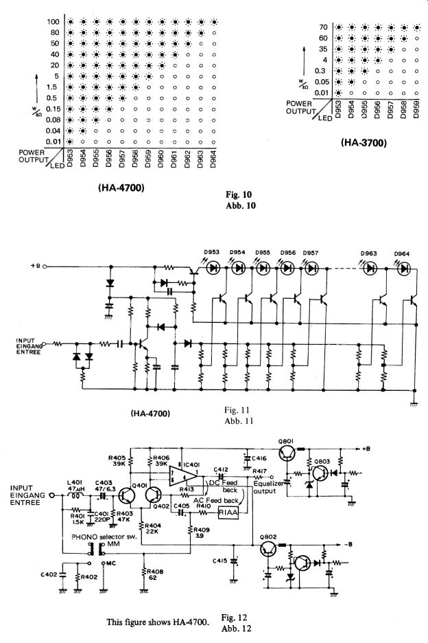
LED power meter drive circuit 12 LEDs (HA-3700 7LEDs) per channel are used to indicate output level. These LEDs and driven by meter circuit; the relationship between the output level and the number of LEDs lit when 82 speakers are connected is as shown in Fig. 10. Incidentally, Fig. 11 shows the operation circuit.
HA-4700
Equalizer amp. circuit (Fig. 12) This circuit is composed of a low noise transistor (2S8C2546) and low noise IC (HA12017) combined, to directly connect an MC cartridge. By this, high sensitivity (input sensitivity: 0.15mV), high S/N ratio (90dB with an MM cartridge, 73dB with an MC cartridge
[converted to 0.25mV input] ) are obtained.
+++++++++++++
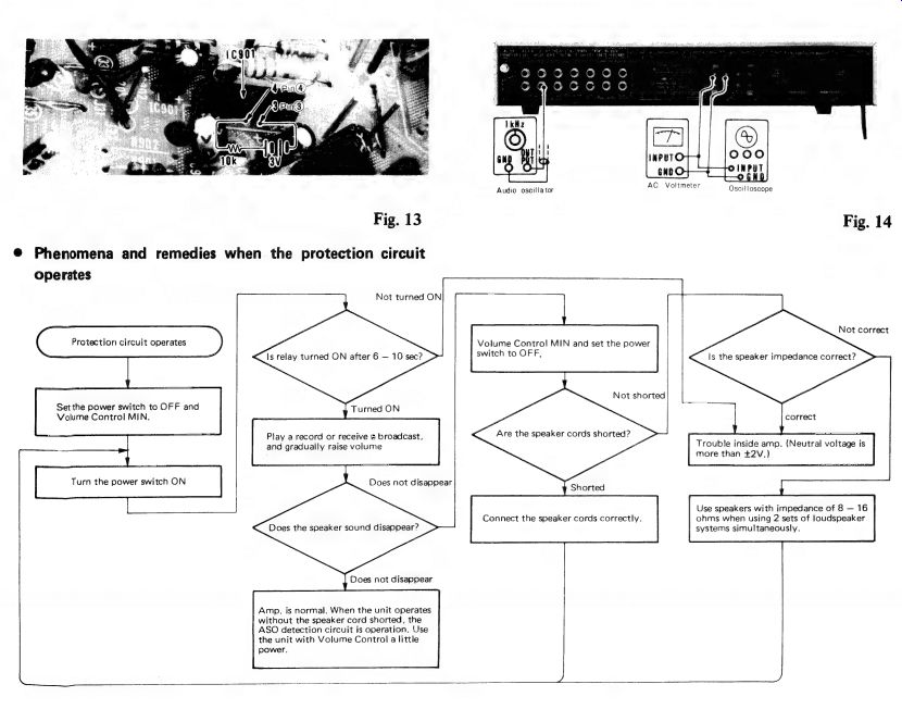
CHECKING THE OPERATION OF THE PROTECTION CIRCUIT
When the output circuit is repaired by replacing the power transistors, etc., perform an operation check on the ASO (Area of Safe Operation) detection circuit and the speaker protection circuit.
1. Operation check of the ASO detection circuit for the output transistors Connect the audio oscillator to the TUNER IN terminals with the speaker terminals unloaded (speaker: disconnect). Set the frequency of the audio oscillator at 1kHz and adjust the level of the input signal so that the voltage at the speaker terminals is approx. 5V rms.
Under these conditions, short-circuit the speaker terminals of the channel to which the input signal is applied using a lead wire, etc. If this short-circuit makes the ASO detection circuit operate, no output appears at the speaker terminals even if the lead wire used for short circuiting is removed.
Next, turn off the power switch and, after approx. 10 sec., turn the power switch on again. When output comes out of the speaker terminals, this indicates that the ASO detection circuit is operating normally.
Phenomena and remedies when the protection circuit
2. Operation check of the speaker protection circuit Make sure that the relay operates (a click sound is heard) approx. 6 - 10 seconds after the power switch is turned on with the speaker terminals unloaded (speaker: disconnect).
Next, when a resistor of approx. 10 k-ohms and 2 batteries (1.5V) are connect in series to the pin 3 and the pin 4 of IC901 on the audio printed wiring board, the relay turns off within 1 sec. When the batteries are taken away, the relay operates again. Next, change the polarities of the batteries and carry out the above mentioned operation to check the operation of the relay.
When the relay operates normally in the above operation, it shows that the operation of the speaker protection circuit is normal. Be careful that the surrounding parts are not short circuited during this operation check.
Audio oscillator AG; Volume Oscilloscope Fig. 14 operates Not turned ON ( Protection circuit operates ) Is relay turned ON after 6 - 10 sec? Volume Control MIN and set the power switch to OFF, Not correct Is the speaker impedance correct? Set the power switch to OFF and Volume Control MIN.
Play a record or receive a broadcast, and gradually raise volume Turn the power switch ON Does not disappear Not shorted Are the speaker cords shorted? Trouble inside amp. (Neutral voltage is more than +2V.)
Does the speaker sound disappear? Use speakers with impedance of 8 - 16 ohms when using 2 sets of loudspeaker systems simultaneously.
Does not disappear Amp. is normal. When the unit operates without the speaker cord shorted, the ASO detection circuit is operation. Use the unit with Volume Control a little power.
---------------
Also see:
Dual turntables (ad) (Feb. 1974)
Source: Stereo Review (USA magazine)