| Home | Audio mag. | Stereo
Review mag. | High
Fidelity mag. |
AE/AA mag.
|
|
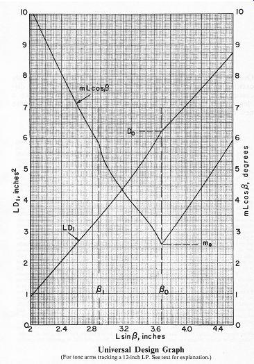
Correct geometry in a pivoted tone arm costs the manufacturer no more than incorrect geometry. But you still can't buy an arm that's 100% correct. There are two kinds of design problems to solve before coming out with a new tone arm. The hard ones and the easy ones. The hard ones are being widely discussed. The proper relationship between tone arm mass and cartridge compliance. Standing waves in the arm and their termination. Pivot bearings and damping. Bias compensation--whether and how to do it. Lead wire stiffness. And so on. All of which we shall explore in depth when we come to our comparative tone arm reviews. But nobody talks about the easy ones. The correct shape of an offset arm. The correct offset angle and overhang for an arm of a given length. The relationship between these parameters and the amount of tracking distortion. In other words, the simple geometry of the tone arm. When the audio enthusiast buys an expensive new arm and takes the shiny instrument out of its polyurethane container, he generally assumes that these elementary problems have been solved by experts and that he is getting an optimized design. He is certainly of no mind to question, let alone recalculate, those super precise mounting instructions. Alas, his simple faith is unjustified. The shape of a tone arm is all too often determined by industrial designers and marketing men, rather than engineers. ("Remember, Hiroshi, American hi-fi nut loves snaky looking tone arm.'') The offset angle is just as often dead wrong for the arm length, and you'll never know whether it happened out of ignorance or sheer mathematical laziness. On top of it, the mounting instructions are likely to be far from optimum even for the given dimensions of the arm. (That, at least, you can do something about. Unless the arm comes as an integral part of a turntable system.) Be suspicious if it looks sexy. Let's look at the easiest problem first. What shape is correct for a pivoted tone arm? (I.e., just about any tone arm other than the Rabco and Bang & Olufsen straight-line tracking arms.) A sexy S? A skinny C? A slightly straightened-out J? Or just a plain obtuse-angled L? The whole thing is ridiculously simple. We all know that, in order to reduce tracking error, the cartridge has to be mounted with an offset (for the moment, never mind how large) and the stylus has to overhang the turn table spindle (again, never mind how much). Now, consider an arm of length L from stylus tip to pivot. (You don't need a diagram; just imagine you're looking down on the turntable from above.) If you draw a line right down the middle of the headshell, coincident with the stylus beam, there will be an angle g (beta) included between this line and L. That's the offset angle. If you now mount the arm with an overhang D (drilling your mounting hole the distance L-D from the spindle), the tracking geometry of your setup is fixed and unalterable. So, as far as tracking error is concerned, it matters considerably less than one small hoot in hell whether the arm tube that carries the offset headshell is straight as an arrow or undulates from here to the bathroom and back again in baroque curlicues. It can't change the value of L or Beta or D. Those sexy, snaky curves aren't calculated to reduce tracking distortion. They're calculated to reduce your sales resistance. Even at the risk of unnecessary com promises in design. In a tonearm, straight is better than curvacious. Since it's the offset angle Beta rather than the curve of the tube that determines the inherent tracking geometry of a tone arm of fixed length, it should be excruciatingly obvious even to math haters that the simplest, and therefore best, solution is a straight tube. A straight line is the shortest distance between two points. (At least in Euclidean space, where presumably all tone arm designers operate.) A straight tube between the off set headshell and the counterweight will have the lowest mass and the greatest torsional rigidity for any given thickness. (We're pleased to see that Dual has broken the industry's uncomfortable silence about this fact of life and is advertising it in connection with the CS-721 turntable.) If the headshell is attached to the straight tube in such a way that the cartridge's approximate center of gravity will coincide with the tube's longitudinal axis, there will be little or no lateral imbalance in the arm and therefore no need for an eccentric counterweight, let alone an outrigger lateral weight. The Grace G-707 is a case in point, as well as the arm on the Dual CS-721. Of course, the four-point gimbal in these designs would prevent twisting in any case, but it helps that the twisting force isn't there to begin with, so there can be no torsional bias on the bearings. An eccentric counterweight, if necessary, is still a fairly elegant solution, as it creates a small torsional counterforce in the simplest and most controllable way. The Formula 4 PLS4/D is a perfect example. Its unipivot suspension responds to the tiniest lateral imbalance with a definite tilt of the vertical hub and a resulting misalignment of the stylus. With most cartridges a slight twist of the eccentric counterweight will restore perfect balance, without in any way compromising the basic straight-line tubular design of the arm. Mind you, we aren't endorsing any of these arms by pointing out the correctness of their straight configuration. Our comparative tone arm tests are yet to come, and there's a lot more to an arm than its basic shape. But correct shape is at least a good start. Is there any justification, then, for a curved arm or are their designers just plain wrongheaded? The answer would be very simple if it weren't for detachable headshells. The fact is that all straight tubular de signs have permanently attached headshells. The arm meets the headshell at an angle, at the corner or on the side of the shell, never in the back. Why this configuration is unsuitable for detachable headshells isn't quite clear to us; it could be a hardware problem involving the size and shape of standard 4-prong connectors. Even that shouldn't be an unyielding obstacle to a technology that put a man on the moon. (A separate, slide-out cartridge holder isn't a good solution, since it just about doubles the mass of the headshell.) In any event, whether you like it or not, all detachable headshells have the connector coming out straight from the back, meeting the locking ring on the arm in a continuation of this straight section. The ring begins to bend only well past the locking ring. Even if we accept this compromise as unavoidable, there's no reason why the arm should be bent in a deep S (a la Technics, Marantz or Pioneer) or a fat J with a sizable outrigger weight (a la SME). That can only create unnecessarily large moments of inertia around the axis of symmetry as well as greater susceptibility to ringing in high-Q materials. The solution is to have two gentle and opposite bends in the arm, no greater than is necessary for the proper offset and lateral symmetry, with perhaps just a tiny outrigger weight for fine tuning the lateral balance. That's still as close as possible to the pure, straight-tube design. An excellent example of this is the fascinating new SAEC arm (WE-308), which we shall re view in depth in the near future. All of this is pretty elementary stuff, requiring nothing more from the tone arm designer than the basic willingness to think mathematically. When we come to the correct values of L, Beta and D, the math gets a bit thicker, but luckily all the groundwork has already been done by some very bright people, so that today's designer needs no greater mathematical sophistication than the ability to look up numbers in a table of trigonometric functions. Why get trapped in a problem that somebody has already solved? The relationship between tracking distortion and tone arm geometry was analyzed in considerable mathematical detail by Benjamin B. Bauer in the 1940s and, even more searchingly, by Dr. John D. Seagrave in the 1950's. Ever since, it has been possible to decide on a practical length for a tone arm and then make both its offset angle and overhang mathematically correct, meaning that any other combination of values would result in higher distortion. It's as cut-and-dried as that. Why even the costliest and most carefully made tone arms deviate from the dimensions worked out in this basic research is beyond our comprehension. But they do. We don't know of a single commercial design in which Beta is optimum for the given L or vice versa. Nor is the D specified in the mounting instructions optimum even for the given values of L and Beta. Most designs make at least token obeisance to the first principle of minimizing tracking distortion, namely that the distortion is directly proportional to the tracking error and inversely proportional to the radius of the groove. But this is almost universally interpreted as, "Make the tracking error zero at the innermost groove and you're cool." And that happens to be a depressingly lazy, not to mention sloppy, approximation. Those neat little protractors furnished by tone arm manufacturers for cartridge alignment (and unquestioningly accepted even by some equipment reviewers) fall into this very trap practically without exception. For example, both the SME and the Formula 4 pro tractors have their alignment point for zero tracking error at a radius of 2.375 in. (60.325 mm), which is the standard spec for the inner most groove before the leadout spiral under the most extreme conditions of groove squeezing. We don't believe we own a single LP recorded that close to the label. Dr. Seagrave specified 2.40 in. (61 mm) as the most extreme case, but quite regardless of that his study proves that a properly dimensioned and mounted arm does not go through zero at the innermost groove. Rather, it zeros twice: the first time somewhere in the middle of the recorded area and the second time close to, but not quite at, the inner most groove. To those who understand the geometry of tracking this should be intuitively apparent, but the actual proof is there in the mathematical analysis. The Grace G-707 specifications are fairly sophisticated in this respect; when mounted according to the template (no protractor is furnished), the arm zeros at a radius of 110 mm and again at 70 mm. But not even this well designed arm has absolutely optimum geometry, as we shall see in a moment. The basic mathematical approach to all this was to solve equations for minimizing, at all points between the first and the last groove, the distortion index m2, which is defined as the tracking error divided by the groove radius. (That comes out in degrees per inch or centi meter or millimeter.) The value of m is of course zero where the tracking error is zero, but the value of interest is its maximum value with different combinations of L, 8 and D. It is this maximum value which must be kept as small as possible. Since this isn't really a technical journal, we won't track through all the math here but are merely reproducing a very detailed and useful Universal Design Graph summarizing the conclusions. The curves are correct for 12-inch LP's only, where the largest groove radius ever encountered is assumed to be 5.70 in. (145 mm) and the smallest 2.40 in. (61 mm). If you happen to be the village atheist and can't accept these given limits at face value, you're out of luck, since the curves are too much bother to recalculate and hardly worth it for the tiny correction factors involved. We are satisfied that the limiting values are realistic for today's records. There are two things you can do with this graph. You can start from scratch and design a 100% correct arm, using only the simplest table of trigonometric functions. Or you can take an existing arm, correct or not, and at least mount it with a 100% correct overhang for its particu lar dimensions. For that you don't even have to look up anything in the tables, if you're willing to fuss with your measurements a little bit. How to use the graph. First, let's define our terms again. The distance L is the length of the tone arm from stylus tip to pivot. The angle B is the offset angle, measured between the line from the stylus tip to the pivot and the line from the stylus tip down the middle of the headshell. The distance D is the overhang, measured from the stylus tip to the center of the turntable spindle when the line L passes through the spindle. (Thus the pivot is at the distance L - D from the spindle.) The distortion index m is the maximum value ("never more than') of the degrees of tracking error per inch under the conditions indicated. The subscript o indicates the optimum case. A very accurate approximation of D can be calculated by obtaining the value of D, from the chart and equating D = D_1 [1 + 0.5 (D_1/L)]. Just don't confuse D_1 with D. To measure L and B on an existing tonearm, all you need is an accurate steel ruler and a plastic protractor divided in half-degrees (not to be confused with the parallel-ruled paper protractors supplied with tone arms). But if you have a triangle with accurate scales on it, you can even dispense with the protractor as well as trigonometric tables or a slide rule. Because the most striking aspect of these design curves is that a single linear dimension, namely L sin Beta, determines the correct D and the best obtain able m for a tone arm of a given length L. All you do is measure the length of the perpendicular from the pivot point to the extension of the line that passes through the middle of the headshell. Simply lay the right-angled edges of your triangle on the tone arm in such a way that one edge passes through the center line of the headshell and the other edge through the pivot point. The distance from the pivot to the right-angled corner of the triangle is L sin Beta. Now read the corresponding LD_1 from the chart, measure L with the ruler and calculate D1, then obtain D from the approximation defined above. That's all there is to it. The really devastating fact revealed by the chart is that, for an absolutely optimal arm, L sin Beta is always 3.68 in. (93.5 mm). Whether the arm is a little shorter or longer, whether it is offset a little more or less, as long as it is designed for 12-inch LP's, that dimension ought to be 3.68 in. But it never is. Don't ask us why. Math is very painful. For example, on the template of the Grace G-707 we measured 3.48 in. On the actual arm we measured 3.375 in. (Tolerances or shaky hands?) Either way, it's close but no cigar. Most other arms don't even approach the correct value. Does it really matter one way or the other? We must keep things in perspective. Minimizing tracking error probably isn't the most important consideration in tone arm design. (Mass and resonances, for example, have undoubtedly higher priority, but we shall discuss that in a future issue, as we've said.) All the damage that tracking error can do is a little second-harmonic distortion on single frequencies and IM distortion on complex signals. There are so many other possible sources of that in the chain of reproduction (a lot of it is cut right into the groove) that the net cleanup effect of correct tone arm geometry is relatively mild. We're inclined to believe that the garbage we hear in typical phono playback is due mostly to other causes. (In the wild and woolly days of the New Yorker Hotel "audio fairs," Walter Stanton used to twist his cartridge about 30 degrees in the headshell to demonstrate that it didn't make an audible difference. On the equipment he used at the time, it really didn't.) There's also the complication of skating force. Reducing the offset and overhang to incorrectly low values will also reduce skating, so that in tone arms without anti-skating bias there may be a beneficial trade-off. (Somebody ought to do a rigorous mathematical analysis of that.) But since nearly all the better pivoted tone arms incorporate anti-skating (even if Joe Grado thinks it should be left disconnected), the question is rather academic. The stylus only knows that it's in equilibrium, not how large the equal and opposite skating and anti skating forces are. And if the anti-skating bias is incorrect, the stylus knows only the net difference between the two forces. So next time you're listening to an arm you really like, you can be reasonably sure of this: It sounds good because the top-priority problems in its design received proper attention. It doesn't sound good because of its geometry. It sounds good in spite of it. Which brings us to the basic consumer issue of the matter. When an audio enthusiast pays a three-figure price for a tone arm or close to a four-figure price for a complete turntable system there's no reason why he shouldn't get the benefit of every little measure of perfection that won't raise the price of the unit even higher. And, to the best of our knowledge, good math doesn't cost a penny more than bad math.
Universal Design Graph (For tonearms tracking a 12-inch LP. See text for explanation. ) ----- [adapted from TAC, Vol.1, No.1 ] --------- Also see: While Waiting for the Perfect Speaker System: Duntech DL-15 (comment) ; Acoustat X (comment) ; Phase Linear Andromeda III (comment) ; Infinity QLS (comment) ; Dahlquist DQ-10 with DQ-1W (test report) Various audio and high-fidelity magazines Top of page |
|
| Home | Audio Magazine | Stereo Review magazine | AE/AA mag. |