
| Home | Audio mag. | Stereo
Review mag. | High
Fidelity mag. |
AE/AA mag.
|
Diamond Styli for True High-Fidelity ReproductionBy Dr. Sao Zaw Win, Win Laboratories, Inc. Stylus tip geometry, diamond quality, cantilever materials and other determinants of stylus performance, mostly foreign territory even to advanced audiophiles, are discussed by a distinguished technologist who “has been there.” Editor's Note: Our obvious respect for Sao Win's comprehensive knowledge of the subject, which prompted us to solicit this article, should in no way be construed as an endorsement of his products, which are received in our laboratory with the same skepticism before testing as all others. Nor should it be assumed that the main thrust of our phone playback investigations is necessarily identical to his; he makes no reference here, for example, to the largely quantum mechanical model of the stylus/groove interface as perceived by researchers such as James V. White, Mitchell A. Cotter and the Teldec group, the purely practical consequences of which appear to be confirmed by our experience. (See also the seminar transcript in this issue.) His basic facts, in any event, speak for themselves. Despite numerous improvements over the years in mechanical and electronic equipment for the playback of phonograph discs, the sound produced still depends firstly on the pickup head and the stylus itself. Therefore, the physical properties of the stylus and the precision with which it is manufactured are of great importance. For many years, the steel needle satisfied most requirements but suffered from disadvantages from the point of view of quality sound reproduction and wear. Then the osmium point was developed, followed by the sapphire. The advent of the vinyl long-playing disc increased the importance of obtaining styli of the hardest material that could take a high polish and have a very low coefficient of friction. Diamond was the choice, but not until 1955 could diamond styli be manufactured commercially on a significant scale. The theory of stylus design. Most performance deficiencies for the re production of discs arise because of the differences in action and nature between the cutting and reproducing styli. It has been more than a decade since low-mass diamond styli first came into practical use for sound reproduction, and while the demand for both spherical and elliptical styli has greatly increased, further improvements have been made both in stylus shape design and production. It is necessary to establish the reasons and understand why these improvements in stylus shape were introduced and why the aforesaid two types of stylus profile have poor potential performance. First, the spherical stylus. It is so named because its basic conical shape is rounded at the tip into a spherical form. The radius of this spherical region is critical because the stylus must fit the groove walls perfectly. (See Figure -------- 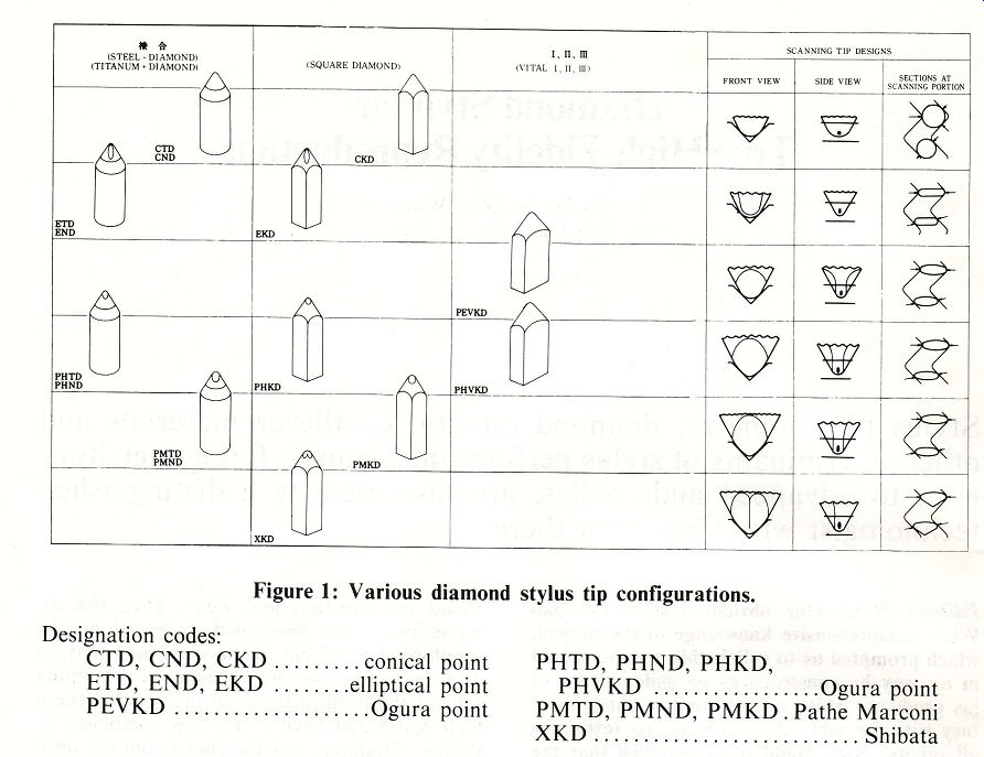 Figure 1: Various diamond stylus tip configurations. Designation codes: CTE ONY, EKD 5.6, conical point PHTD, PHND,”PHKD, ETD, END, EKD ........ elliptical point FEPIRERST, O55 00 es Ogura point PENYRI) I., ans suns sates ia Ogura point PMTD, PMND, PMKD . Pathe Marconi BE i thane nmin sings won ams Shibata 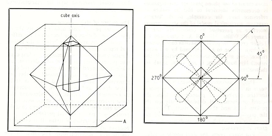 Figure 2: Orientation of cube, octahedron and rod; Figure 3: Orientation of cube, octahedron and rod, as seen normal to cube plane. ----------- 1, styli CTD, CND and CKD.) As can be seen, if the radius is too large, the stylus will ride along the top of the groove; if it is too small, the stylus will bottom in the groove. In either case, mistracking will occur; in addition, a bottoming stylus will become fouled with dust dug out from the normally untouched bottom of the groove, thereby increasing noise and distortion. Out of this critical fit two main problems arise: one is tracing distortion and the resultant pinch effect; the second is inner-groove distortion. Tracing distortion occurs because of the way the distance between the groove walls varies with changes in the direction of the groove. This is the result of the flat chisel shape of the cutting stylus; when the deviation from nominal is considerable, the reproducing stylus is forced vertically upwards. Since a stereophonic pickup head is sensitive to vertical stylus motion, this movement due to what is normally called “pinch effect” causes distortion. Inner-groove distortion is also directly linked to the nature of the spherically shaped tip. The outer grooves on the disc are longer than the ones closer to the center, so that the distance covered by the stylus in one revolution at the beginning of the record is far greater than toward the end. To produce modulations of a given frequency on any part of the disc, the cutting stylus must vibrate at a constant rate. However, near the center of the disc there is less space to accommodate the same rate of vibration and, as a result, high-frequency modulations in the inner grooves become so cramped that their radius of curvature may sometimes be smaller than the spherical tip radius. Therefore the stylus will no longer remain in contact with the groove walls and distortion is generated. In order to eliminate the problem, a play back stylus as similar as possible to the cutting stylus was developed. This was the elliptical stylus (Figure 1, styli ETD, END and EKD). With its longer axis across the groove, it is far less susceptible to the problems of pinch effect, and the smaller ends are able to trace the tiny modulations at the inner grooves. There is a serious problem, however: because of the small contact area with the groove wall, the elliptical profile exerts greater pressure on the grooves and can cause damage. (But see also the discussion of contact area and vertical tracking force in the seminar transcript. -Ed.) Here 'effective tip mass'-which is a combination of various factors such as the mass of the stylus, the mass of the cantilever, and the Young's modulus of the cantilever- plays an important part. Technically we can assume that weight reduction of the diamond tip and of the cantilever reduces effective tip mass. In practice, however, reduction of stylus tip size is limited by the need to retain a particular tip configuration. There must also be a minimum size of diamond stock for operator handling in the manufacturing process, since orientation must be kept to close tolerances from the first step of production right down to the bonding of the stylus onto the cantilever. With the advent of CD-4 discs and of the recent PCM and direct-to-disc recordings, the elliptical profile required a higher tracking force resulting in greater pressure on the groove walls. Unless the contact radius was at the same time limited to 7.6 microns, it would not trace the CD-4 carrier frequency fully. With an elliptical stylus of 7-micron side radius measured under 45° to the longitudinal axis, the high-frequency modulations of the groove wall are abraded because of the small contact area. The rate of record wear is also combined with a higher rate of stylus wear. For these reasons, new methods were developed to in crease the contact radius and produce a tip profile which is very close to the shape of the cutting stylus, with an elongated zone in the contact area at a 90° included angle. (See Figure 1, styli having designations beginning with PE, PH and PM.) This elongated zone is in practice limited by basic tolerances both in the groove itself (not all discs are cut with equal precision) and in cartridge/arm geometry (VTA, tone arm alignment, etc.); errors could cause the stylus to ride high near the top of the groove wall on one side, with the tip very low on the opposite wall. Research has shown that when all these parameters are given due consideration and everything is properly aligned, a long radius of 70 microns with a center 24 microns away from the main axis will give excellent results if the short radius is not smaller than 6 microns. Under 6 microns, with a nominal tracking load of about 2 grams, the abrasion starts again. The upper limit must be between 8 and 9 microns on account of the elasticity of most vinyl mixes, which is approximately 0.376 x 10 ^-10 cm/dyne. ------------ 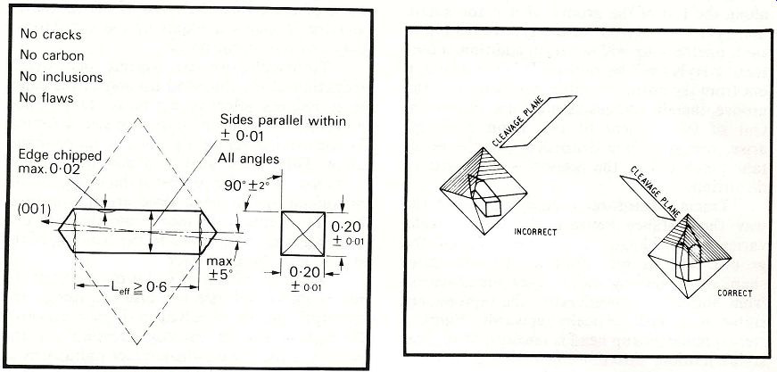
Figure 4: Specifications of oriented square rods for stylus fabrication. Figure 6: The two extremes of orientation of the rod within the octahedron. (Left) The worst orientation; (right) the best orientation. 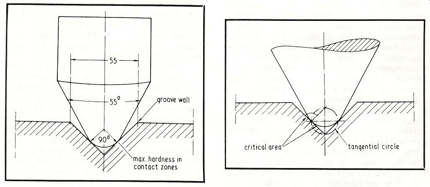
Figure 5: Stylus in correct orientation with respect to groove walls. Figure 8: The tangential area of the stylus in relation to the groove wall. -------------- Figure 1 also shows a Shibata stylus patented by the Victor Company of Japan (see stylus XKD). The shape is very close to that of the cutting stylus; the parabolic front side is created by two facets intersecting a polished cone, and the blending in of the sharp corners creates a small uniform radius over the whole contact area. But, the major radius being large, this stylus profile extends too dangerously close to the bottom of the groove; hence the possibility of mistracking as a result of the tip bottoming and getting pinched out of the groove under high modulation. In principle, all these cuts-the Shibata, the Bang & Olufsen Pramanik, Ortofon's Fine Line, Shure's Hyperelliptical and ADC's Aliptic-stem from the tip shape that was patented for Pathe Marconi in 1954, the only differences being that, to create this shape in the contact area, different methods are applied by using flat facets, rounded facets, cones, etc. (See Figure 1, stylus PMKD.) From all of the above explanations it now follows that an ideal version of the stylus must be cut or generated without facets. It could be described as an intersection of two cones with blended corners. While close to all of the above styli in configuration and design, this ideal version must also have smaller contact radii of 50 microns and 6 microns, ensuring not only that the contact area will be extended beyond what is normally attained by other designs but also that the small groove modulations will be tracked successfully. By also extending the area of contact upwards, so that the greater part of the stylus below the nominal disc surface is actually in full contact with the groove wall, this configuration applies less pressure and at the same time avoids the major problem common to all CD-4 styli, which have tips extending dangerously close to the bottom of the groove. Such an ideal stylus tip configuration actually exists and is called Paroc by Weinz of Germany and Vital by Ogura of Japan. This type of cut has only one disadvantage: since the oval cross section cannot be detected under low magnification in a microscope such as is needed to handle the stylus, mounting on the cantilever becomes very expensive and difficult. Special provisions and tooling have to be made. Diamond selection and fabrication. Diamond styli are produced in three different qualities, which depend upon the size and nature of the natural diamonds. Three diamond sizes are used: (1) well-formed, flaw less octahedrons; (2) small, 500-per-carat stones selected from grit; and for the cheapest styli (3) tiny, 1000-per-carat diamonds. (A carat is a unit of weight for precious stones equal to 200 milligrams.) The highest-quality styli are manufactured from octahedrons whose size depends upon the length of the stylus shank required. The initial stage is to prepare a rectangular rod of diamond from an octahedron. The orientation of the rod to the crystal symmetry is of extreme importance. The long axis of the rod must be within 3° of the cube axis, as seen in Figure 2, and the flat sides of the rod must be parallel to the octahedral edge (i.e., the 45° plane joining the two cube axes), as indicated in Figure 3. Square-section blanks are produced in sizes ranging from 0.14 x 0.14 mm cross section by 0.50 mm length, up to 6 x 6 mm cross section by 8 mm length. The larger blanks are produced by sawing a rectangular rod from a well-formed, flawless octahedron. The starting point for the best styli consists of extra fine-quality selected natural crystals of size 100 to 400 per carat, with no chips, flaws, carbon or other inclusions. (See Figure 4.) Orientation of the longitudinal axis is normally parallel to one main axis of the diamond crystal, in other words from 4 point to 4 point or in the (001) plane in crystallographic terms. The orientation can be done by means of X rays; however, on the smallest stones of about 0.2 mm diameter, the process takes several hours because of the low mass of the diamond to be penetrated by the X-rays and the low reflection density. This expensive orientation process ensures that the 4 point of the diamond will be well within the radius and that the 2 point (i.e., the 2-fold axis) will be normal to the groove wall when the record is played, thus presenting the hardest and most wear resistant section to make contact. (See Figure 5.) The orientation of the 500-per-carat size is less easy, as these stones are so small that they cannot be processed into rods. Some orientation can be obtained, but it is not al ways possible to arrange that the point of the tip will be within 3° of the cube axis. The smallest crystals (1000 per carat), used in the cheapest styli, are simply tumbled to a usable size; since orientation is impossible, it is a matter of chance whether the hardest part of the tip will be in contact with the groove walls. ------------------ 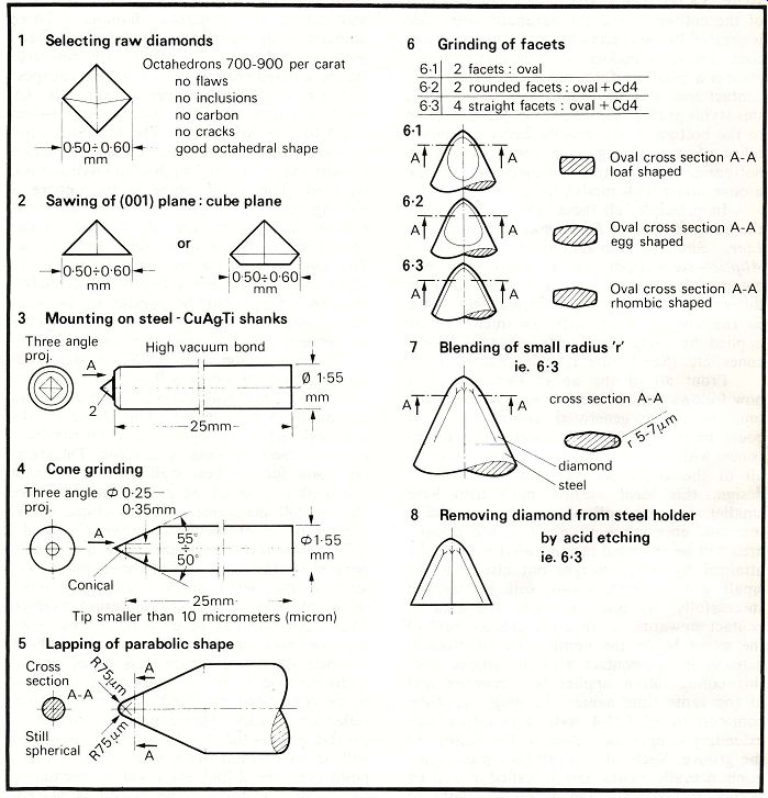
Figure 7: The main stages of production of a low-mass diamond stylus from a conical blank. 1 Selecting raw diamonds Octahedrons 700-900 per carat no flaws no inclusions no carbon no cracks good octahedral shape 2 Sawing of (001) plane: cube plane La «LN wil) 50+0- 60/=- -0 50+ io 60I= mm I 3 Mounting on steel - CuAgTi shanks Three angle High vacuum bond 4 Cone grinding Three angle @ 0-25- Tip smaller than 10 micrometers (micron) 5 Lapping of parabolic shape Cross Ps spherical 6 Grinding of facets 6-1] 2 facets: oval 6-2I 2 rounded facets: oval + Cd4 6-3] 4 straight facets : oval + Cd4 - Oval cross section A-A “ loaf shaped aD Oval cross section A-A egg shaped Oval cross section A-A 0) rhombic shaped 7 Blending of small radius 'r' ie. 6-3 EY cross section A-A 8 Removing diamond from steel holder by acid etching ie. 6:3 ------------------- Orientation of the diamond is extremely important because when the hardest part of the diamond is in contact with the groove walls the wear on both the diamond and the disc is minimal. Deviation from this orientation reduces the life of both the diamond and the disc. The worst orientation is where the longitudinal axis of the diamond rod is normal to an octahedral plane. In such a case the octahedral planes will tend to cleave off and the diamond will act as a turning tool, destroying both it self and the groove walls. (See Figure 6.) Figure 7 illustrates an alternate method, showing the typical stages in the production conical blanks for diamond styli of low mass. Stages 1 through 4 show that after the sawing of the cube plane the blank is bonded to a steel support (which is later removed) in order to facilitate polishing of the tip. The surface of the bonding area on the diamond is made rough and frosty to get a good bond to the steel support and later to the cantilever of the stylus assembly. Bonding is done under high vacuum to eliminate oxidation and to achieve a good bond of diamond to metal. Stages 5 through 6 show the grinding and polishing of the stylus tip. The cone surface is fine-ground with a 600-mesh wheel and then polished with an 800 wheel. Cone grinding is done on special machines that take into account the crystal lographic orientation of the diamond in order to minimize the effects of differential hard ness, which could otherwise produce an oval cone. The polishing ensures the obtainment of a very sharp point, which is extremely important for subsequent grinding of the radius. The cone sides are not polished in the mass production of the cheaper styli, as only the radius at the very tip is involved in actual contact with the groove walls. (See Figure 8.) The diamond tip is then removed from the steel support by acid etching, so that the mass is considerably reduced. The weight of the conical blanks-and also of nonoriented ball-shaped blanks-after finishing as diamond styli is 0.2 x 10⁷° gram, whereas the weights of cylindrical and square diamond rods after finishing are 1 x 10~° and 1.4 x 10° gram respectively. Cantilevers. The cheapest version of a stylus cantilever is a conical aluminum tube. These are used mainly with bonded nonoriented tips. A more expensive cantilever is a low-mass full beryllium rod of 0.30 mm diameter. The advantage is that beryllium is of lower density than diamond (1.8 as against 3.5 grams per cubic centimeter). Some ceramic substances such as alumina (A1203) and hot-pressed silicon nitride have been tried; however, their modulus of elasticity is not as good as of beryllium. The latest developments indicate that boron, with its favorable ratio of density or specific gravity to Young's modulus, is the best suited for cantilever material. Boron has the further advantage that it is less expensive than beryllium and is absolutely nontoxic (unlike beryllium, which is quite poisonous), so that operator handling is easier and potential health hazards are eliminated. (See table of comparison of material characteristics.) -------
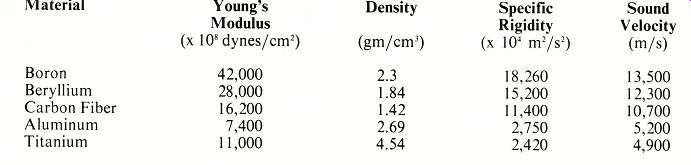
Table of Comparison of Various Cantilever Material Characteristics Material Young's Modulus (x 10* dynes/cm?) Density Specific Sound Rigidity Velocity (gm/cm?) (x 10° m/s?) (m/s) Boron Beryllium Carbon Fiber Aluminum Titanium ------------ Bonding. Normally, the diamond tip is bonded directly to the cantilever by means of high strength epoxy resin. The big disadvantage is that the stylus starts to shift position as the epoxy hardens or polymerizes because of contraction. Shrinking the aluminum or beryllium around the diamond is another possibility, but the absolute sizes are too small for obtaining a reasonable opening by cooling the diamond or heating the metal cantilever or both. The latest technique is the bonding of diamond to boron, etc., under high vacuum by using a special silver solder. This must be done by wetting the diamond and the boron at the same time in the active bond with silver solder and titanium. Special tooling is used to prevent the displacement of the diamond stylus tip when the solder starts to flow, as surface tension pulls the diamond tip in all directions, thus tending to dislocate the diamond from the optimum position. This metallic bond is advantageous for its quick heat sinking qualities, keeping the diamond stylus tip cool at high modulations. Also, no phase shift will occur under actual playing conditions as might happen with epoxy on account of the latter's elasticity due to the acceleration of the stylus tip itself. Conclusion. The audio world has at least as good reasons to value the diamond, this amazing form of carbon, as jewelers do. Truly, the phono industry would grind to a halt in its absence. It is a good idea to take our cue from the best jewelers and refuse to consider anything but diamonds of the highest quality for our phono styli. A good phonograph record deserves the best diamond as well as optimum tip geometry and cantilever design. Acknowledgements: The author wishes to thank Dr. Ernst Weinz of Weka GmbH, Idar Oberstein, West Germany, and Mr. Hiroshi Ogura of Ogura Jewel Company, Tokyo, Japan, for their technical inputs and valuable papers. --------- [adapted from TAC] --------- Also see: Cartridge/Arm/Turntable Developments FM Tuners: A Hopeless Dilemma for the Serious Audio Reviewer: NAD 4080; Sequerra Model 1; Series 20 Model F-26; Yamaha CT-7000 Why We're So Mean, Vindictive, Arrogant, Negative--and Truthful Various audio and high-fidelity magazines Top of page |
|
| Home | Audio Magazine | Stereo Review magazine | AE/AA mag. |