Troubleshooting consumer electronics audio circuits can be as simple as learning your ABC’s or starting to take a step as a child. You begin with the basic audio circuits and how to use audio test equipment. Then, you learn how audio circuits react and perform, and finally, you learn how they are tied together. Besides learning how to service audio circuits, the electronic hobbyist or beginner learns how to solder, remove, and replace defective components. Even the electronic technician that only repairs TVs and VCRs might return to audio basics, and add another product to the service bench. Above all, you can receive many high and low rewards, sometimes even defeat, but still have fun while servicing electronic audio products.
The most popular audio circuits are found in many different consumer electronic products such as, the table radio, AM-FM-MPX stereo receiver, phonograph, cassette and CD player, auto radio CD/cassette player, and the TV to name a few ( FIG. 1). Of course, there are special audio circuits found in the telephone answering machine, audio test equipment, camcorder, high powered amplifier, and the everlasting high-priced tube amplifier.
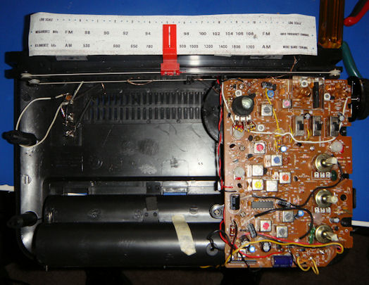
FIG. 1. The internal view of a GE “SuperRadio 3” portable radio with a
5 1/2 inch speaker.
[http://earmark.net/gesr/sr3.htm]
Audio circuits within the consumer electronic field produce a sound that is audible to the ear. The sound might be clean and clear, or weak and distorted. The audio frequency (AF) amplifier operates within a frequency range of 20 Hz to 20 kHz. Very few men, 50 years old, can hear above 10 kHz, while some women can hear above the 15 kHz range.
The sound we hear from the 1 inch to the large 15 inch speakers or a little old pair of headphones, is produced by a preamp, AF, driver and power output circuits within the consumer electronic product. Sometimes audio circuits appear simple and easy to repair, but then again, the intermittent sound problem can be down right mean to service.
THE BLOCK DIAGRAM
The block diagram is a simplified schematic of an electronic audio system with the various stages or circuits found in boxes. It’s a simplified version of the various audio circuits. The block diagram shows how the various stages are tied together. Often, arrows point to the various boxes indicating how the signal path travels or power supply sources feed the other circuits. You can quickly isolate the defective sections in the electronic block circuits. Locating the circuits upon the electronic chassis is another hill to climb.
When checking the block diagram of a defective audio amp within the boom-box cassette player, you can quickly locate the defective circuit by various symptoms ( FIG. 2). For instance, when the sound is distorted at the speaker, suspect the audio output circuits.
FIG. 2. The block diagram of an early audio amplifier with an AF, driver and two transistors in push-pull operation.
Suspect a front-end or open tape head when a loud rushing noise is heard in the speaker. When a low frying noise is heard all the time and controlled by the volume control, suspect a defective component ahead of the volume control. Suspect a weak or open component when the stereo amp circuits won’t balance up, and on it goes.
THE RIGHT ONE
The first peek at a schematic diagram of a clock radio output circuit might appear complicated to some, but if you break the schematic down into the various sections or circuits, servicing becomes much easier. For instance, if music from the radio speaker is quite weak and faint, go directly to the volume control and check the signal at that point in the audio circuit. Determine if the loss of signal is ahead or after the volume control. Proceed through the audio circuit with a signal tracer or scope to determine where the music becomes weak.
Many different manufacturers don’t list the various voltages upon the schematic of transistor or IC components. Some list only the symbol and number of each part and no values. An electrolytic coupling capacitor might have a part listing with no value or working voltage; You might find the resistor’s value and wattage missing from the circuit. The zener diode might have a part symbol with no zener voltage. Only one fixed diode symbol might be found in a low voltage power supply bridge circuit. When the various voltages, values and part numbers are missing, servicing the audio circuits can be more difficult.
A lot of the manufacturers have the complicated audio circuits of a high powered amplifier (above 100 watts) with the part symbol number and no voltage applied to the higher watt age transistors. You may find in the other stereo channel the same parts are marked with voltages or a separate voltage chart of each transistor is listed in a table format. When the operating voltages are listed in a chart or table, you must apply them to the transistor or IC in the circuit. It’s best to mark the voltages on the schematic, from the chart, before at tempting to service the audio chassis.
Some manufacturers have arrows or thick black lines indicating the signal path from stage to stage within the cassette-recorder. Here one can trace the recorded or playback signal very quickly through the various amplifier circuits. Some schematics have voltages listed in various colors. After locating a defective component, circle it and draw a line out to the side of the margin area to record the service problem. Now take correct voltage measurements and mark them on the transistors or IC components in the audio circuit.
VOLTAGE IN TESTS
The most common test instruments used in taking voltage measurements are the VOLT- OHM-METER (VOM), digital-multimeter DMM, and FET-VOLT-OHM-METER (FET-VOM) ( FIG. 3). A quick method to locate a defective component in a given circuit is with voltage measurements. By taking voltage measurements on the transistor or IC terminals, you can determine if the circuit or component is defective. A quick forward bias voltage measurement between the emitter and base terminals of a transistor can indicate a defective transistor. Critical voltage measurements through the audio circuits can quickly locate a defective component or circuit.
The DMM is ideal in measuring critical voltages in the solid-state audio circuits. A normal silicon transistor may have a forward bias of 0.6 volts, while the normal germanium transistor has a forward bias of 0.3 volts dc. You can quickly determine if a transistor is open or leaky with a forward bias voltage reading between base and emitter terminals. Some electronic technicians take a quick forward bias measurement on all transistors in the electronic chassis to locate the defective component or circuit.
FIG. 3. The VOM, DMM and FET-VOM test instruments are used in making voltage measurements in solid-state circuits.
Check the voltage measurements and compare them with those found on the schematic diagram. Rotate the function switch of DMM to the desired voltage range. If the over-range display comes on, turn to a higher voltage scale. The over-range symbol might be a 1 or “L” figure. One of the biggest advantages of the DMM is to indicate the correct voltage polarity without changing test leads. The DMM takes very accurate low voltage measurements found in solid-state audio circuits.
Take critical voltage measurements of all transistors within the audio input circuits ( FIG. 4). Clip the negative (-) probe to chassis or common ground and place the positive (+) probe to the collector, base and emitter terminals in that order. Compare these voltages to those located on the schematic. Remember, the collector voltage is higher or more positive than the emitter or base terminal (NPN). A very low collector terminal voltage might indicate a leaky transistor or improper power source. A close voltage measurement on all three terminals may indicate a leaky or shorted transistor. No voltage measurement upon the emitter terminal might indicate an open transistor or emitter resistor. Higher than normal voltage found on one of the transistors in a push-pull output circuit might indicate an open transistor in the ground circuit.
FIG. 4. Taking voltage measurements upon the early PNP input amplifier stages with the DMM.
The VOLT-OHM-METER (VOM) was one of the first meters placed on the market to take voltage, resistance and current measurements. The VOM can load down the circuit producing inaccurate measurements. A VOM can make quick continuity tests of low resistance components, broken wires, and PC wiring. The VOM is not as accurate as the DMM or FET-VOM when taking critical voltage and resistance measurements.
The VOM is ideal when used as a meter monitor in tape head azimuth adjustments and other alignment procedures. The meter hand can be easily seen to raise or lower, where the DMM numbers change very rapidly, in ac alignment adjustments.
The FET-VOM (analog meter) is a brother to the vacuum tube voltmeter(VTVM). The FET VOM has a very high impedance input and does not load down the circuit to be measured. The FET-VOM is a VOM meter employing a field-effect transistor amplifier circuit. This meter is more accurate than the regular VOM in taking voltage and resistance measurements. The FET-VOM is ideal when making alignment and adjustment procedures. Like the VOM, the FET meter must reverse test probes when the meter hand goes the wrong way. This meter is a great deal more accurate than the small VOM in voltage, resistance and current measurements. Of course, the FET-VOM meter costs three or four times the pocket VOM, but it’s worth it. The DMM and FET-VOM meters are two dependable test instruments in servicing electronic audio circuits.
RESISTANCE MEASUREMENTS
A resistor offers opposition to current flow in the electronic circuit. The many different kinds of resistors can be accurately checked with the DMM or FET-VOM test instrument. Choose the DMM when taking low resistors under 10 ohms. The digital-multimeter can indicate a poor switching contact under a fraction of an ohm. Remove one end of a resistor to take accurate resistance measurement; this is especially so with 500k or higher ohm resistors in the electronic circuit. The amplifier circuits should be turned off when making resistance measurements.
The FET-analog multi tester might measure ac and dc voltages from 0 to 1000 volts. The resistance measurement might measure resistance from 0 to 10 megohms. The analog FET meter may measure current from 0 to 100 uA, 1 to 300 mA, and up to 10 amps.
Some FET-multi testers have a continuity buzzer that sounds when the resistance of the circuit being tested is below 300 ohms or less. Start with the highest voltage range or above the minimum battery or supply voltage since the analog meter hand will crash against the meter peg.
The analog meter probes must be reversed when the polarity is wrong and the meter hand goes backwards. Don’t apply voltage to the test leads when the range selector is in ohm or current position. Don’t attempt to measure RF voltage with the analog meter. Remember that the voltage and resistance measurements of the FET-VOM are made with the meter connected parallel to the component. Current measurements are made with the meter connected in series.
Accurate resistance tests can be made with the DMM in or out of the circuit. Measuring resistors in circuits containing transistors and diodes is quite accurate with the DMM. The digital multimeter quickly and accurately checks the critical tolerance of emitter resistors in transistor circuits. Comparable resistance measurements of stereo tape heads might determine if the tape head is defective or not. The impedance of an 8 ohm speaker voice coil will measure around 7.5 ohms with the DMM and 7 ohms upon the FET-VOM tester.
TRANSISTOR IN-CIRCUIT TESTS
The suspected transistor can be tested in or out of the circuit. The in-circuit transistor tester or the diode-function test of the DMM can quickly test transistors within the audio circuits. It’s possible to receive an improper reading when a diode, low ohm resistor, or another transistor is directly attached or paralleled with the transistor to be tested. If a certain transistor has an improper reading, the transistor might be defective or have another low resistance component across it. Check the schematic to determine if the transistor is shunted with another transistor or fixed diode.
If in doubt, quickly remove the base terminal from the circuit and take another in-circuit test. Remove the base terminal from the PC wiring with solder-wick and soldering iron. Sometimes by just touching the transistor with a test probe the intermittent transistor will act up. If the suspected transistor tests open or intermittent while being tested, replace it. Replace any transistor that has a high-resistance junction test compared to the other elements.
A quick method to check a transistor in or out of the circuit is with the diode or transistor test of the digital multimeter (DMM). Remember, general purpose audio transistors have diodes back to back and can be tested with the diode test of the DMM. The early transistor audio circuits were made with PNP transistors. Today, most transistor audio circuits contain NPN types.
The unmarked or unknown transistor terminals can be checked with the transistor tester or junction-diode test of the DMM. Remember, the base terminal measurements are common to the collector and emitter terminals with the diode test of the digital multimeter (DMM). The resistance measurement is always lower from base to emitter than base to the collector terminal. Place the positive (+) probe from the DMM on the base terminal with the NPN transistor. Likewise, place the negative probe of the DMM on the base terminal for a PF’JP transistor test.
When the transistor terminals are unknown within the audio circuits, start first with the NPN diode test. Today, most audio circuits have NPN type transistors. Place the red probe to one of the terminals and see if you can get a resistance measurement on one other terminal. Switch the bias test leads if there is no reading; you may have the wrong polarity or the transistor is a PNP type.
When you receive a transistor resistance measurement, leave the positive probe on that terminal and switch the negative probe to the other terminal. If the transistor is a NPN type and the red probe is at the base terminal, you should get a resistance measurement between the base and emitter terminals, and base and collector terminals.
BASIC AUDIO CIRCUIT TESTS
You have now identified the base terminal and the transistor is an NPN type, because the base terminal of an NPN transistor is always positive and is common to the emitter and collector terminals. Notice what terminal with the base terminal has the highest measurement. This is the collector terminal. The remaining terminal must be the emitter terminal. Double check the measurement between base and collector terminal with the highest resistance reading.
The defective transistor might be open, shorted, leaky, intermittent, or have a high-resistance junction. An open transistor might not show any measurement between base and collector or base and emitter terminals. A leaky transistor will show a low resistance between any three elements. The shorted transistor might have a leakage below 5 ohms. Most transistors become leaky between the collector and emitter terminals. A high-resistance diode-junction is generally above 1K ohms ( FIG. 6).
FIG. 6. The normal DMM transistor test with the diode test of a DMM and high junction resistance measurement.
FIG. 5. Checking for correct transistor test with the diode test of a DMM and high junction resistance measurement. 2N3904
Test each transistor with the diode-tests of the DMM. Place the red probe (positive) of an NPN transistor at the base (B) terminal and the black probe (negative) at the collector (C) terminal of the suspected transistor. Note the normal diode-junction test resistance. Leave the red probe (+) at the base terminal and place the black probe (-) at the emitter terminal. Both readings should be quite close with a normal transistor.
Now reverse the procedure with the red probe at the collector and the black probe at the base terminal. Likewise, place the red probe at the emitter and black probe at the base terminal. Both measurements should have an infinite reading that indicates the transistor is good or normal.
If a low resistance measurement is found below 100 ohms, in both directions, the transistor is leaky ( FIG. 7). The transistor is shorted between two elements if the measurement is below 5 ohms. A leaky or shorted transistor will have a low ohm measurement with reverse test leads in both directions.
TRANSISTOR OUT OF CIRCUIT TESTS
Transistors can be tested very accurately when removed from the circuit. They can be tested in a commercial transistor tester, digital multimeter with a transistor gain hFE test, and the diode-test upon the DMM. The commercial transistor/FET tester might identify transistor leads, leakage paths, dynamic gain, a good or bad scale, Bi-polar transistor Beta, Dynamic Beta, Bi-polar leakage, and tests the field effect (FET) transistor with analog meter movement.
The lower priced transistor/diode tester with LED indicators, checks all types of diodes such as germanium silicon, power, LED’s and zener. A LED-transistorized tester might indicate a NPN or PNP transistor, and checks all types of transistors as germanium, silicon power, RF, audio, switching, and FET’s. The tester indicates a leaky or shorted transistor, open, and relative beta of two transistors.
FIG. 7. The transistor might be leaky between any two elements or all three terminals.
FIG. 8. Checking the suspected transistor out of the circuit upon an LED transistor tester.
IC CIRCUIT TESTS
Integrated circuits (IC) are found in the preamp, AF and power output circuits of the audio stages. An IC might include the AF and power output circuits in one chip. In fact, one large IC might include both stereo output circuits in the low and high powered output circuits.
One audio IC might include all the audio circuits within the portable cassette player.
The defective IC can be located with signal in and out tests, critical voltage and resistance measurements. Check the audio signal going into the IC chip terminal with an audio signal tracer, signal injection, and scope. If signal is found going into the IC and no sound at the output terminal, suspect a defective IC, defective components tied to the IC terminals, or improper supply voltage. The defective IC might become leaky or open.
Check the supply voltage pin terminal coming from the low voltage source. Take a peek at the schematic and see which pin has the highest applied voltage ( FIG. 9). The terminal pin might have a Vcc mark on the supply voltage terminal. Measure the voltage applied to the supply pin to common ground. Suspect a leaky IC when the supply voltage is a lot lower than marked on the schematic.
FIG. 9. The highest voltage measured upon a normal IC is the supply pin terminal (Vcc).
Remove the terminal pin from the PC wiring. Remove the excess solder from around the pin with solder-wick and soldering iron or suck up the solder with a desoldering iron. Make sure the terminal pin is free and loose. Take a resistance measurement between pin and common ground. Replace any IC that has a low resistance to chassis ground.
Take critical voltage and resistance measurements for each IC terminal pin. Compare these measurements to the schematic. If one or two pin terminal voltages are low or high, take a resistance measurement from that pin to ground. Check for a possible leaky capacitor or a change in a resistor, if the pin has a low resistance measurement. Suspect an open IC when all voltages and resistance measurements are quite close to those found upon the schematic. When the audio signal goes into the IC and not out, remove and replace the suspected IC.
THE DOCTOR IS IN
Before the medical Doctor can decide what is wrong with your illness, he or she must know the symptoms. Likewise, the electronic technician must know the symptoms before tearing into the audio circuits. The audio output sound symptoms at the speaker might be dead, weak, distorted, erratic, or intermittent sound.
Now determine if the weak symptom is ahead or after the volume control. A weak stage might be caused by a defective coupling capacitor, transistor, IC, or improper voltages. Often, the distorted speaker symptom is produced in the audio output circuits. The erratic or intermittent sound might result from a defective coupling capacitor, transistor, IC, or poor board connections, anywhere in the audio circuits. Take the symptom from the speaker and apply it to the block diagram or schematic to locate the defective circuit.
I CAN’T HEAR YOU
The weak sound problem might be compared to the old electronic technician, who used to hear a TV, clock radio and boom box player operating at the same time; and at once he can pick out the product, when the sound became intermittent. Now, he cannot hear his wife within ten feet and the TV set must be turned up to full volume; the sound is weak and a hearing aid might solve the audio problem.
The coupling capacitor, bias resistors, transistors and IC components cause most of the weak sound problems within the audio circuits ( FIG. 10). The dead symptom is much easier to locate than the weak or intermittent problem. Check the weak sound symptom by signal tracing the audio from stage to stage with an external audio amp or scope. Then, take critical voltage and resistance measurements where the sound stops, to locate the defective component. An open or leaky transistor or IC might cause a weak audio problem.
The weak sound and distorted symptom might be produced by a frozen speaker cone. A distorted and weak sound might result from a leaky or shorted output transistor or IC. The input and output terminal of an output IC can be signal-traced with the scope or external audio amp. Suspect the IC or improper voltages if the input terminal is normal and the output terminal is weak and distorted. Compare the normal stereo channel to the weak and distorted one with voltage and resistance measurements.
BASIC AUDIO CIRCUIT TESTS
FIG. 10. Check the following components for weak sound in the tape cassette player.
THAT SOUNDS TERRIBLE
Distorted music not only sounds terrible, but it’s difficult to listen to. A very weak distorted symptom is difficult to locate. Transistors, ICs, speakers, resistors, capacitors, and sound alignment produce most distortion problems in the audio circuits. Extreme distortion is often found in the audio output circuits. Locate the distorted audio circuit with the external audio amp and scope.
A leaky coupling capacitor can cause some distortion in the sound circuits. Check for a leaky or shorted transistor in the driver, AF or output stages for a distortion symptom. Don’t overlook burned, open or a change in resistance of bias resistors within the base and emitter circuits. Carefully inspect each bias resistor when locating a shorted or leaky transistor ( FIG. 11). A change in resistance of a collector or emitter resistors can cause distortion. Check for leaky diodes in the base circuit of a transistor output circuit.
Suspect a defective output IC for audio distortion. If the audio input signal is normal and the output of the IC is distorted, suspect a defective IC. Take accurate voltage and resistance on the IC terminals to determine if the IC is open or leaky. Improper supply voltage might indicate a leaky IC or improper voltage source. One audio channel can be distorted and the other stereo channel normal with a dual-output IC. Check for leaky bypass capacitors on the IC terminals.
FIG. 11. Check the bias and collector load resistors after locating a shorted transistor.
Sub another PM speaker for one that might cause distortion. A frozen voice coil or dropped cone can produce a distorted sound. Suspect the cone frozen against the PM magnet when the sound is tinny or mushy. A speaker blatting sound might be caused at higher volume with loose cone or speaker spider section. Loose dirt or particles in the cone area might cause a vibration noise. A blown voice coil is the result of too much power applied to the speakers.
Low distortion might result from leaky coupling and bypass capacitors, a change in resistance, and leaky AF and driver transistors. Often low signal distortion occurs in the preamp or AF circuits. Very low signs of distortion are very difficult to locate. Low distortion can be located with a square wave generator and scope, or a distortion meter.
Extreme distortion can be caused by a leaky output transistor or IC component. Check the output circuits for extreme audio distortion. Often leaky or shorted output transistors and IC’s might have burned or open bias resistors. Check for a leaky driver or AF transistor that is coupled directly to an output transistor for distortion. Don’t overlook a leaky diode or electrolytic coupling capacitor that might produce extreme distortion. A blown speaker voice coil can cause extreme distortion.
POPS IN AND OUT
Erratic sounds or sound that pops in and out can be caused by transistors, IC’s, speakers, poor terminals and board connection. In the early table or auto radio chassis, when only one power output transistor was found in the output stage, these power transistors would produce a popping noise with intermittent audio. A poor flexible speaker connection at the voice coil can cause a loud off and on noise. Suspect a dual-power output IC component with popping noises in the sound.
Try to isolate the erratic sound with an external amp and signal trace the popping noise through the amplifier circuits. Replace the suspected semiconductor, if the popping noise is not heard at the base terminal of a power output transistor or IC and the noise is heard at the input terminal. Replacing the transistor or IC is the only answer as voltage and resistance measurements won’t give any indications of a popping component or circuit. Often, the defective transistor or IC output component runs very warm.
HERE TODAY, GONE TOMORROW
The intermittent audio problem may act up at once or go for days before the music stops. The intermittent component is easy to locate if the music comes off and on at once. Usually the intermittent product should be left to operate in the home, when it takes hours or days to cut up and down.
Although, any electronic component can cause an intermittent condition, look for defective transistors, IC’s, poor part connections, corroded terminals, and poor board connections. Determine if one or both channels in a stereo circuit are intermittent. Compare the normal channel with the intermittent channel in stereo sound circuits. It’s possible to have one half of a dual-IC intermittent and the other channel normal ( FIG. 12).
FIG. 12. One channel of a dual-input IC might be distorted while the other channel is normal.
Monitor the intermittent audio circuit with external power amp or scope. Isolate the sound stages by starting at the volume control. It’s best to cut the audio circuits in half to locate the intermittent component. Notice if the sound is intermittent ahead of the volume control or within the output sound circuits. Now go from stage to stage to monitor the intermittent audio. Check from base to collector on transistors and input terminal to output terminal of IC components. Check on both sides of a coupling capacitor to locate the intermittent capacitor.
Intermittent components, such as transistors and IC’s can be sprayed with heat or coolant to make the intermittent to start up or stop. Poor board connections can be located by moving parts around upon the PCB. Push up and down upon the PC board with an insulated tool. Sometimes poorly-tinned part terminals might produce an intermittent connection under a large blob of solder. Check for poor socket and wire terminals for intermittent connections. Don’t overlook an open or poor speaker voice coil connection for intermit tent sound.
VACCINATION TIME
A dead or weak audio circuit can be signal traced by injecting a signal from the audio or noise generator. Inject an audio signal (1 kHz) at the center volume control terminal to signal trace the audio output circuits. If the signal can be heard in the speaker, proceed to the front-end audio circuits. The signal can be injected from a noise generator to locate a defective RF or AF stage.
Inject the audio at the tape head terminal of the cassette player or preamp-amp circuit of an AM-FM receiver. Check the schematic for the input and output terminal of a suspected preamp IC. Inject the audio signal at the input and then the output terminal until a sound is heard in the speaker. Proceed through the circuit until the sound is heard.
Likewise, inject the audio signal at the base or coupling capacitor of the preamp sound circuit ( FIG. 13). Inject the signal on both sides of the coupling capacitor to determine if the capacitor is open. Go next to the collector terminal of the preamp transistor. Proceed through the audio circuits until the 1 kHz tone can be heard.
For instance, if sound can be heard with the signal injected at the collector terminal and not on the base, you have located the defective stage. Test the suspected transistor open or leaky conditions. Then take critical voltage and resistance measurements
FIG. 13. Inject a noise or tone generator signal at the base of coupling capacitor to signal trace a preamp sound circuit.
A dead audio circuit is found with an open coupling capacitor, leaky or shorted transistor or IC. Often a weak sound is heard with a shorted or leaky component. Sometimes a weak sound condition might bleed through with an open coupling capacitor. Check for poor soldered terminals for a no sound symptom. The open speaker voice coil or poor sol terminals can cause a no sound problem.
CHASING THE DOG
Signal trace the audio circuits with the audio signal generator and external audio amplifier. The external amp, speaker or scope can be used as indicators or monitors. Insert a test or music recording cassette to signal trace the audio through the cassette or boom-box player. A CD disc can be played to test the music from stage to stage in the amplifier of player. The tough dog sound problem can be signal-traced stage by stage with the sine or square wave generator and scope ( FIG. 14).
Inject the audio signal at the volume control and if the audio is normal at the speaker, the defective stage is ahead of the control. Start at the volume control and signal trace the audio output if the preamp stages are normal. Sometimes the electronic technician start at the speaker with the external amp and work backwards through the sound circuits.
The external audio amp can be used as indicator to test out the audio circuits. Start at the volume control and go from base to base of each AF or output transistor with the audio amp. When one stereo channel is dead, weak or intermittent, play a cassette or inject audio signal into both channels. Now compare the audio at each stage with the good stereo channel. Likewise, inject the audio signal at the input terminal of a suspected preamp or output IC and signal trace the audio at the output terminal.
When one large dual-IC is found in the stereo audio circuits and the left channel is weak and distorted, signal-trace the distortion through the audio circuits with the scope or external amp. Keep the volume control on the external amp as low as possible to not add distortion to the original audio signal. Check the signal on each side of an electrolytic coupling capacitor to the IC input circuit. Make sure the supply voltage source is measured at the IC or collector terminal of each audio transistor. Compare the audio signal with the normal channel.
THE ORIGINAL, THE SUB, THE UNIVERSAL
Most audio transistors and IC components can be replaced with the original or universal replacements. Replace all high-powered and MOSFET audio transistors with the originals. Large and special IC components should be replaced with the original part number ( FIG. 15). Some original foreign and Japanese semiconductors are now available from wholesale and mail-order firms. The small signal audio transistors can be replaced with universal types without any problems.
Special volume, treble, bass, dual, and balance controls must be replaced from the manufacturer. The many position function switches found in cassette players and receivers should be replaced with originals. Replace large high-wattage column speakers with the right part number. Special gears, idlers, and pressure rollers must be replaced with the manufactured part number. Replace selector matching knobs and dial assemblies with the exact part number.
FIG. 14. Signal trace the weak or distorted audio problem with the square wave generator and scope.
Small electronic parts such as resistors, capacitors, fuses, and some switches can be replaced with universal replacements. The original filter capacitor might mount in a small space and can be replaced with universal capacitors. Filter capacitors can be added or paralleled when the original is not handy. You can replace a 1000 uF electrolytic capacitor by paralleling two 500uF filter capacitors. A can-type filter capacitor with several capacitors in one section can be subbed with universal capacitors. Make sure the capacitor and working voltages are the same or higher. The defective 2000uF 35 volt electrolytic capacitor can be replaced with a 3000uF 50 volt filter capacitor.
The leaky or shorted power supply diodes can be easily replace with universal units. A 2.5 amp 1000 volt diode can replace the 1 amp 500 volt fixed diode. When a special bridge diode is not available, make up a bridge-diode circuit out of four fixed diodes with the same or higher amperage and voltage. Make sure the correct polarity of each diode is connected into the bridge circuit.
THOSE TINY CREATURES
The surface-mounted device (SMD) is a miniature component that takes up very little mounting space. The SMD part is found in today’s TV set, VCR, camcorder, compact disc and cassette player. Also, they are found in hand-held portable radios, telephone, wireless telephones, cellular, pagers, scanners, and receivers of all kinds. You must have a steady hand, good eyesight, and a lot of patience to locate and replace SMD components ( FIG. 16) The SMD part is mounted directly on the PC wiring.
FIG. 15. Replace special and high-powered transistor and IC’s with originals.
Because many surface-mounted parts have similar shapes and sizes, sometimes they are difficult to identify on the PC wiring. Some of these parts look like black, brown or white specks on the PCB. The commercial resistors might appear as round, flat, leadless devices. The ceramic capacitor is a flat, solid part with the terminal connections at each end. These connections are tinned with solder for easy circuit mounting. The fixed resistor might have several white numbers stamped on top of a black body to identify the resistance value. A fixed SMD ceramic capacitor might have a line at the top with a letter of the alphabet and numbers. Sometimes universal ceramic capacitors have no value marked on top ( FIG. 17).
FIG. 16. SMD components are tiny compared to standard electronic parts.
FIG. 17. Since many SMD parts don’t have any markings, keep them in packages they were shipped in.
Transistors and diodes are often identified with two letters or a letter and number. The SMD component terminals are found at each end, except transistors and IC chips. Of course, the SMD IC has many gull-wing terminals, while the transistor has only three. The commercial surface-mounted transistor (SMT) might appear in a chip form with flat contacts at one side, top and bottom, or on both sides. You might find more than one transistor in one chip. The same applies to fixed diodes and LED’s; two or more diodes might be found in one chip. You can test these SMD semiconductors like the standard component.
These SMD components are miniature in size and must be handled with care. Since these parts are so tiny, they can easily be lost or flipped out of sight. The special SMD component should be replaced with the original part number from the manufacturer. Of course, some of these parts can be replaced with universal SMD parts such as fixed ceramic capacitors, resistors, diodes, LEDs, and some universal transistors.
Identify the SMD part that is soldered directly on the PC wiring, while larger components are mounted on top of the board. The chip resistor value can be identified with numbers stamped on top. A ceramic chip capacitor might have a letter with a number along side ( FIG. 18). The electrolytic chip capacitor can be identified with a white line at one end, indicating the positive terminal with the value and voltage marked on top of the chip. remember, the standard electrolytic capacitor has a black line that indicates the ground side. The electrolytic ceramic chip capacitor has the opposite polarity sign (+).
FIG. 18. The ceramic chip capacitor and resistor might be marked on top of part with numbers and letters. Fixed Ceramic Capacitor Chip; Fixed Electrolytic Chip; 1000 OHMS; A = 100 pF; White Positive Terminal
The SMD transistor has three terminals with two on one side and the other on the top side. The terminals might be marked 1,2 and 3. Sometimes the chip might have two transistors in one component. The ceramic IC chip has many terminals on each side, while some microprocessors have gullwing-type terminals. The SMD transistor or IC might have the part marked on top or no markings at all. Some transistors are marked with a number and letter on the top side ( FIG. 1 The digital transistor might have a resistor in series with the base and emitter terminal inside the chip. You must have a magnifying glass to identify the small numbers and letters on top of the SMD component.
FIG. 19. Check the three-legged transistor chip with a number and letter on top.
Remember the ceramic chip capacitor is a non-polarized capacitor. Likewise, the fixed chip resistor is the same. You can solder any end into the PC wiring without any problems. The ceramic chip electrolytic capacitor is polarized and the line at the end must be mounted to the positive terminal or connection. A universal SMD aluminum electrolytic capacitor is polarized with a black edge or line (-) on top of the capacitor. The negative terminal is mounted at ground potential. The capacity and working voltage might be stamped on the top side. Remember, the electrolytic capacitor must be installed correctly or if in back wards, it can overheat, blow fuses, and might blow up in your face.
IC chips are not heatproof or shockproof. These devices are made of ceramic or plastic molding, and they should not be subject to direct shock. Don’t apply extra stress to the IC chip. Handle SMD semiconductors with extreme care. These sensitive semiconductors might appear in dark protective envelopes ( FIG. 20). Keep all SMD components in the original package until they are ready to be mounted.
FIG. 20. The sensitive semiconductors might appear in dark static-free envelopes.
The IC terminals are identified by a small circle indented on top of the IC. The dot indicates terminal 1. You can count off the number of terminals to take voltage and resistance measurements. Keep those test probes sharp so they won’t short out any two gullwing terminals. Sometimes the IC part is marked on top with white letters. The surface-mounted IC processor has many gullwing terminals and is very difficult to remove and replace ( FIG. 21). Check the soldered connection of the SMD component for intermittent sound and cracked or poor soldered connections.
LOSS OF HIGH FREQUENCY
The defective tape head might cause distortion, one dead channel, intermittent playing or recording, and a howling noise. Weak and distorted music may result from excess oxide packed on the tape head. In fact, the small gap might be full of oxide dust resulting in no music from the tape head. Clean the tape head with alcohol and a cleaning stick before taking tests or checking the tape head.
FIG. 21. The surface mounted IC’s are tiny compared to the standard integrated circuit.
Inspect the tape head for excessive worn marks when a weak and tinny noise is heard in either channel. A loss of high frequency might be caused by a worn tape head. Often, the sound of music becomes weak and tinny compared to the normal channel. Replace the tape head if worn marks are found on the tape surface or tape head. Demagnetize the tape head after repairs are made to eliminate any background noise.
DON’T SCREW UP
Simply stay out of critical and difficult audio circuits if you don’t have the correct test equipment, schematics or knowledge. Don’t try to touch-up alignment or adjustment screws to increase the sound level if the correct tools and test equipment are not available. Trying to adjust bias controls within high powered amplifiers might make matters worse without the correct instructions. Leave these repairs to the electronic technician who is a specialist in servicing special sound circuits.
. ===