|
|
Amplifier Types
While the characteristic curves of a tube are very useful for selecting a quiescent operating point, they are not very convenient for determining the voltage gain Av of an amplifier stage. What is needed is a simple model for the triode amplifier stage, and an equation describing its behavior, which relates the voltage gain Av to the tube constants p , g and rp and the value of load resistor RL. Such a model is shown in Fig. 14. The triangle represents a perfect amplifier with voltage gain - u . In series with this amplifier is a resistor of value rp, related to the plate resistance of the tube rp’. For the simplest possible amplifier without any local feedback (such as the amplifier of Fig. 11), rp’ = rp. If a cathode resistor Rk is inserted between the cathode and ground is used to bias the tube or provide local feedback, and if Rk is not paralleled by a bypass capacitor, and value of rp’ becomes: rp’ (u + 1)Rk + rp. This resistor, and the load resistor RL, form an attenuator, reducing the overall gain. The voltage gain of the overall amplifier is then: Av = - u RL/(RL + rp u) = - u RL/ + (u + 1)Rk + rp). This equation shows the behavior mentioned above: when the value of RL is very large (much larger than rp’) the voltage gain of the stage is - u. The gain is negative because the amplifier is inverting: a positive-going input signal produces a negative-going output signal. The circuit model for a pentode operated with its suppressor grid connected to the cathode and the screen grid operated at a constant positive voltage with respect to the cathode is the same as for a triode.


Fig. 14. Common cathode amplifier stage and circuit model.
The circuit of Fig. 14 is known as a common cathode amplifier stage. Most voltage gain stages in preamplifiers or power amplifiers use several such stages connected in series. A coupling capacitor is used to connect the various stages for audio signals, while isolating the different DC voltages at the inputs and outputs of the stages.
The resistor Rk serves two purposes. It biases the cathode of the tube to a positive voltage with respect to the grid, so that the tube is operated in its most linear region where no grid current is drawn. The resistor Rk also provides some local negative feedback. This feedback stabilizes the voltage gain and improves the linearity (lowers the distortion) of the amplifier. It accomplishes this by making the voltage gain more dependent on the value of Rk and RL (which, if good quality components are used, do not change as an audio signal is being amplified) and less dependent on the tube characteristics p and rp, which will vary slightly when the tube is amplifying a signal. From the equation for Av it is easy to see how a large value of Rk reduces the effect of rp and p on the amplifier’s voltage gain. As Rk is made very large, ( u + 1)Rk becomes much larger than rp + RL. In this case the equation for Av reduces to Av = u RL/ u +1)RKI. Usually the amplification factor p is much greater than 1, so when Rk and p are large the gain becomes approximately Av = —RL/Rk. Such an amplifier stage will have a gain of much less than — u , but because the effect of p and rp on the gain are negligible, the distortion will be very low, and the gain will not change as the tube ages and its characteristics change.
The manner in which the cathode resistor Rk improves the linearity of the amplifier can also be explained in terms of feedback. The voltage appearing across the cathode resistor is a fraction Rk/RL of the output voltage V. This is true because the same signal current i passes through both Rk and RL. When the control grid of the tube is negatively biased with respect to the cathode, the control grid does not draw any current, so there is only one electrical circuit and one signal current which circulates from the ground, through Rk, the tube, RL, and back to ground (via the power supply Ebb. The output voltage Vo is given by Vo = —is RL. The voltage across Rk is given by Vk = isRk = -(Rk/RL)Vo.
The vacuum tube amplifies not the input voltage V but V_gk : the voltage appearing be tween the grid and cathode. This voltage is the difference between the input voltage V and the cathode voltage Any distortion appearing in V at the amplifier’s output will also be reflected in Vk. The voltage V_gk will contain this distortion component, which is inverted in polarity with respect to the distortion in the output voltage V When this distortion component is amplified by the tube, it may be considered to subtract from the larger output distortion
[…??]
quency signals, while blocking the DC voltage appearing at the output of the first stage. There is no coupling capacitor between the output of the second common cathode amplifier and the cathode follower amplifier stages. In this case the DC voltage appearing at the second stage’s output helps to bias the cathode follower stage tube. This DC voltage is typically quite high, on the order of Ebb! This allows a large value resistor Rk to be used to bias the cathode follower output stage, ensuring good linearity for the stage.
The amplification factor of the tubes usually employed in preamplifier voltage gain stages ranges from about 30 to 100. Because the voltage gain of a common cathode amplifier stage is usually only about 0.5 u to 0.8 u, the overall open loop (before negative feedback is applied) gain of an amplifier like that shown in Fig. 12 is limited to 6400 or less. Most often the gain will be on the order of 2000 (66 dB). This is not enough gain if a moving coil cartridge is to be used without a separate head amplifier. Consider the case of a low level amplifier for moving coil cartridge use with a gain at 1 kHz of 50 dB (a reasonable figure). Due to the necessary RIAA equalization which must take place, the amplifier’s closed loop gain at 20 Hz is nearly 80 dB (an increase in gain by a factor of 10 times corresponds to exactly 20 dB). The amplifier’s open loop gain must be greater than this by the desired amount of negative feedback at low frequencies. For stable, low distortion operation, at least 12 dB of feedback and preferably more should be used. The open loop gain of the low level amplifier should therefore be on the order of 82 - 90 dB.
One obvious way of increasing gain is to increase the number of amplifier stages. There are several problems with this proposed solution. Adding another common cathode amplifier stage would provide sufficient gain, but the amplifier would probably become unstable when feedback was applied around the circuit. Also, because three polarity inverting stages are in cascade, the overall amplifier becomes inverting. A different configuration feedback circuit would then have to be employed, and such a circuit introduces other technical difficulties. The solution of adding a third common cathode amplifier stage is not an acceptable one.
A pentode common cathode amplifier stage might be tried in place of one of the first two triode stages, but this too has several drawbacks. Pentodes tend not to be as quiet as triodes, and the need for a screen grid power supply complicates the design of the preamplifier. A good solution is to use two triodes in a compound circuit called a cascode (as opposed to cascade) amplifier stage.
A typical cascode amplifier stage is illustrated in Fig. 17. Two triode tubes, connected in series, are used in this circuit. The bottom tube functions as a conventional common cathode amplifier stage. The upper tube functions as a common grid amplifier stage. In a common grid amplifier, the input voltage is applied between the cathode and ground, while the grid is connected to ground for audio signals. In the circuit of Fig. 17, the capacitor connecting the grid of the upper tube to ground serves acts to ground the grid for audio signals, while allowing the DC electrode voltages of the tube to be correctly set for linear operation. In some cases this capacitor is connected to the cathode of the bottom tube. Either connection gives similar performance. The resistor in series with the cathode of the upper tube serves to bias its grid negative to the cathode.
Unlike a common cathode amplifier stage, the input impedance of the common grid stage is quite low. The signal current through the load resistor RL also passes through the series connected triodes. The lower tube must supply all this current to drive the cathode of the upper tube. Compare this to the case of the common cathode amplifier stage, which has a high input impedance (at least at low frequencies) because the grid draws almost no signal current. This low input impedance means that the effective load resistance on the common cathode stage is low, so it normally provides little voltage gain. The common grid stage can have a substantial voltage gain, however, so that the complete cascode amplifier can have appreciably more gain than a simple common cathode amplifier.
The cascode is a two stage amplifier, and acts like one at high frequencies. This means that a complete amplifier consisting of a cascode stage, a common cathode stage, and a cathode follower may or may not be stable. Fortunately the low input impedance of the upper tube which lowers the voltage gain of the common cathode stage also extends this stage’s high frequency response. By careful design, a stable amplifier with enough gain for a moving coil cartridge can be achieved.
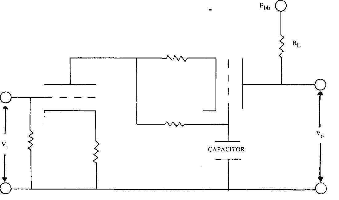
Fig. 17. Cascode amplifier stage. Note: location of capacitor
Vacuum tubes find other uses in preamplifiers and power amplifiers other than as amplifying devices. A triode (or less commonly a pentode) can also be used as a “constant current source. “ Such a circuit is illustrated in Fig. 18. The designation “constant current” is misleading because the tube does not supply a completely constant current to the circuitry of which it is part. What it does is to function as a very large value resistance for signal currents, so that when the voltage across the current source circuit is changed, the current through it varies only slightly. It is employed where the use of a comparably large value resistor would cause a prohibitively large DC voltage drop. Suppose an amplifier stage requires an effective load resistance of 100 k-Ohm, and the stage draws 10 mA of plate current. If an actual resistor were used, the voltage dropped across it would be (100,000 ohm ) (0.01 A) =1000 V. A very high voltage power supply would therefore be required, the resistor would dissipate large amounts of heat, and the circuit would be very wasteful of power. Alternatively, a tube current source could be used, and only about 200 V would have to be dropped across the entire current source circuit. Obviously this is a much more practical solution.
However, tubes are not perfectly linear devices, as was noted before, while resistors are nearly perfectly linear. A vacuum tube current source can itself be a source of amplifier distortion. The effective resistance RL’ of the tube current source for signal voltages (its dynamic resistance) depends on the amplification factor M and the plate resistance rp of the tube. While .i remains relatively constant independent of changes in voltage across and cur rent through the tube, this is not true of rp whose value can change significantly as the cur rent through the tube is varied. For a given output voltage, this current variation will be less as RL’ is made larger. This suggests that the value of Rk should be made as large as possible. When the value of Rk is large, the effect of changes in rp on RL’ is diminished, and the variation in rp is minimized. The battery B in Fig. 18 allows the use of a large value resistor for Rk while maintaining correct biasing for the tube. Sadly, a number of commercial preamplifiers use tube current sources without such a battery. This limits both the linearity and the voltage gain Qf the circuit. Finally, a tube current source will be noisier than an equivalent resistor, and this must be considered when current source loaded input stages for low level amplifiers are being designed.
All vacuum tubes are noise generators, but some tube types are quieter than others. There is a general relationship between the noise voltage produced by a tube and its transconductance gm. One way of quantifying this noise voltage is in terms of an equivalent noise resistance. Resistors are noise generators too, and there is a definite relationship between the noise voltage produced by an ideal resistor and its resistance. The noise resistance of a tube is defined as the value of an ideal resistor which would produce the same amount of noise as the vacuum tube. For most tubes, the value of noise resistance is approximately equal to 2. . This means that high transconductance tubes are generally quieter than low transconductance tubes. Tubes and resistors generate noise of all frequencies, so the noise voltage of a tube or resistor is usually specified over given range of frequencies (the bandwidth). In a given bandwidth, the total noise is proportional to the square root of the resistance: the noise doubles when the resistance is quadrupled. Therefore to halve the tube noise generated in an amplifier stage, the transconductance would have to be quadrupled.
The transconductance of a tube does vary slightly with changing plate current, increasing as the plate current is increased. Low noise stages will therefore tend to operate at comparatively high currents. Large decreases in tube noises cannot be obtained in this manner. When the transconductance of an individual tube is too low to provide sufficiently low noise operation, several tubes may be connected in parallel. Two identical triodes, with amplification factor u , plate resistance rp, and transconductance gm, when connected in parallel are equivalent to a single triode with amplification factor u’ = u, plate resistance rp’ = r and transconductance g 2 gm. Vacuum tube head amplifiers often make use of this fact, connecting two or four triode sections in parallel, for a noise reduction of about 3 to 6 dB respectively if the various triode sections are equally noisy. Even if one of the sections is moderately noisier than the others(s), there is a net reduction in generated noise. A noisy tube in parallel with a quiet one will always be equivalent to a single tube which is at least slightly quieter than the noise tube alone.
Power Supplies for Vacuum Tube Amplifiers
It is important to recognize that all of the circuit schematics presented thus far in the Figures have shown ideal battery sources (Ebb, etc.) as part of the vacuum tube amplifier stages. When such circuits are actually constructed, real world power supplies must be used. If these power supplies are not correctly designed and constructed, the amplifier may per form poorly or not at all. It is easy to overstate the importance of power supplies, just as the significance of any single factor in a complete amplifier design can be overemphasized. Power supplies can affect the sound of a preamplifier or power amplifier however, so a discussion of the principles of power supply design as they relate to vacuum tube amplifiers is in order. Vacuum tube amplifiers contain two principle classes of power supplies: heater sup plies, and plate (and sometimes grid) supplies. The heater supply will be discussed first.

Fig. 18. Vacuum tube constant current source and current source loaded common
cathode amplifier stage.
The heater power supply provides the current required by the heater wire in each vacuum tube which heats the tube’s cathode, causing the emission of electrons. As was discussed earlier, the electron current which the cathode can provide depends on the cathode’s temperature, which in turn is determined by the current through the heater wire. This means that the characteristics of the vacuum tube, and therefore the performance of the amplifier stage, depends on the value of the heater current. If the power supply does not provide a suitably constant heater current, the amplifier may malfunction. One possible cause of heater current variations are changes in the AC line voltage. Your local power company does not keep the AC line voltage to your home constant. The line voltage changes on both a long term and short term basis as other power users switch electrical equipment on and off The AC line also usually contains very brief voltage spikes produced by lightning strikes, the turn-on and turn off transients of electrical motors, and the like. All these AC line voltage variations will be passed on to the heater power supply unless the power supply designer intervenes.
A properly designed voltage regulator can solve the problem of line voltage variations. A voltage regulator is a circuit which delivers a constant output voltage even though the input voltage to the circuit may be varying. Voltage regulators for heater supplies are very easy to design using IC’s, and can inexpensively deliver excellent, reliable performance. There is no good reason why the heaters of a vacuum tube preamplifier should not be regulated. Because the preamplifier is a high voltage gain circuit which is itself followed by additional gain stages (in the power amplifier), the effect of any heater current variations in the preamplifier will be magnified by the succeeding gain stages. Heater regulation is useful in any vacuum tube amplifier design, but it is vital for a stable preamplifier design.
Voltage regulation can also help to isolate the various stages making up a complete amplifier. A perfect voltage regulator also delivers a constant output voltage even though the current drawn from the regulator may be varying. In an unregulated power supply, if one heater draws an excessive amount of current it can lower the supply voltage, which in turn would decrease the current available to the other heaters sharing the same power supply. A good regulated power supply would maintain the correct supply voltage, ensuring that the current drawn by each heater is unaffected by the current drawn by the heaters of the other tubes.
These same benefits of voltage regulation are important for plate and grid power sup plies. Changes in the AC line voltage will be reflected in changes in the value of Ebb unless counteracted by a voltage regulator, and these voltage fluctuations can find their way into the audio signal being amplified. The effect of a voltage regulator in isolating individual amplifier stages is also important. If the power supply is not correctly designed, and it allows the various amplifier stages to interact, a signal in one amplifier stage can give rise to a spurious, distorted replica signal in another stage. This interaction between amplifier stages can lead to poor sound quality, and even oscillation. All these problems can be prevented by employing voltage regulation in the plate and grid power supplies. The same degree of isolation between amplifier stages can be obtained by using one or two very high quality voltage regulators to supply all the audio circuitry, or by using a number of simpler voltage regulators, each supplying only one or two stages. Either solution can yield excellent results, but the latter is usually easier to implement in an actual amplifier.
Amplifier stages can also interact with each other via the ground return wiring. As amplifier designs become more elaborate, using a larger number of higher current amplifier stages, grounding plays an increasingly important role in ensuring a stable, quiet, good sounding amplifier. Proper layout and grounding technique in a vacuum tube amplifier is just as important as good power supply regulation. One is of little use without the other.
Preamplifier Circuits
Before discussing the different types of preamplifier circuits, it is useful to describe the purpose and function of preamplifiers. Once the need for a preamplifier is understood, the merits of the different types of circuits can be assessed.
The purpose of the low level amplifier stage of a preamplifier is to amplify the (low) voltage produced by the phono cartridge as it plays a recording. The vast majority of phono cartridges are electromagnetic transducers of some type. They convert the mechanical waves cut into the record groove into a facsimile electrical wave: the cartridge’s output voltage signal. The audio signal (mechanical wave) cut into the record groove is small, and the phono cartridge is an inefficient transducer, so its output voltage is very low. If this were the only problem, the design of low level amplifiers would be fairly simple, mostly a matter of designing an appropriately quiet input stage.
Both the manner in which records are cut and the physical laws governing the behavior of a magnetic cartridge make matters more complicated, however. Magnetic phono cartridges are velocity sensitive transducers: the cartridge’s output voltage is proportional to the velocity of the stylus as it traces the mechanical wave cut into the record groove. In contrast, ceramic and strain gauge cartridges are amplitude sensitive transducers. Their output voltage is proportional to the physical size of the mechanical wave cut into the record groove.
These two classes of phono cartridges will behave differently when a record is played. Consider a 33 1/3 RPM record on which a 1 kHz sine wave (pure tone) has been recorded. Suppose that both types of cartridges produce the same voltage when playing this record. Now the record is replayed at 66 2/3 RPM, turning the 1 kHz sine wave into a 2 kHz sine wave (the turntable’s doubled speed makes the mechanical waves cut into the record groove moves the phono cartridge’s stylus back and forth twice as fast as before). The amplitude of these mechanical waves has not changed, so the amplitude sensitive transducer will pro duce the same output voltage as before. The doubled record speed has doubled the stylus velocity however, so the signal voltage generated by the velocity sensitive transducer will also double.
If records were cut so that the amplitude of the mechanical waves impressed on the record groove were proportional to the sound pressure level of the original musical event, and if all cartridges were amplitude sensitive transducers, there would be no need to equalize the signal generated by this phono cartridge. Records are not cut this way, however, and magnetic cartridges are velocity sensitive transducers. This is why equalization is necessary in the low level amplifier of a preamplifier.
The dominance of a magnetic phono cartridge has come about because of the technical advantages of such a design. Records are (supposed to be) cut according to a standard which minimizes the total amount of equalization which must be performed by the low level amplifier. Suppose that records were cut with a constant amplitude characteristic, so that the amplitude of the mechanical waves cut into the record groove was proportional to the sound pressure level of the original musical event. Then, for a fixed original sound pressure level, the output of a magnetic phono cartridge at 20 kHz would be 1000 times its output at 20 Hz. To produce a constant level voltage at the output of the low level amplifier, the amplifier’s voltage gain at 20 Hz would have to be 1000 times its gain at 20 kHz. This is a lot of equalization. Instead, parts of the frequency range of a record is cut with a constant velocity characteristic: the velocity of the mechanical wave cut into the record groove is now proportional to the sound pressure level of the original musical event. Over these frequency ranges, a magnetic cartridge requires no equalization. The gain of the low level amplifier need not decrease with increasing frequency over the constant velocity frequency ranges of the record.
The RIAA standard specifies that from 500 Hz to 2.1 kHz, and below 50 Hz, that records be cut with a constant velocity characteristic. From 50 Hz to 500 Hz, and above 2.1 kHz, records are to be cut with a constant amplitude characteristic. Actually, the transition from constant velocity to constant amplitude characteristic and vice versa is made smooth, and is specified in such a manner that the equalization necessary in both the cutting and playback parts of the reproduction chain can be achieved using simple circuitry. The manufacturers of magnetic phono cartridges, in turn, strive to produce cartridges which are perfect velocity sensitive transducers. These two facts imply a standard for the equalization which must occur in a preamplifiers’ low level amplifier. The gain must be flat from 500 Hz to 2.1 kHz and below 50 Hz. The gain must drop from 50 Hz to 500 Hz, and above 2.1 kHz.
There are two fundamental manners in which this equalization can be achieved. Negative feedback can be used to control the gain of the low level amplifier in a frequency selective manner. This is called active RIAA equalization. An actively RIAA equalized preamplifier circuit was illustrated in Fig. 16, in which R0, R1, R2, C1 and C2 formed a negative feed back network providing RIAA equalization. A second method is to use a simple resistor-capacitor filter network to passively equalize the audio signal. In this case, the amplifier stages in the low level amplifier are designed to have an overall constant gain. These stages may or may not have an overall negative feedback loop around them. A typical design is shown in Fig. 19.
These two different approaches to the RIAA equalization problem have different strengths and weaknesses. Vacuum tube feedback amplifiers tend to have rather low open loop (before feedback) voltage gains. This requires that the feedback component values be carefully selected based on a knowledge of the amplifier’s open loop gain. If this gain changes (caused by the aging of the tubes, for example), the equalization accuracy can suffer. The problem is far from insurmountable, but it does require careful thought during the design process. A passively RIAA equalized preamplifier can be designed to be much less sensitive to tube aging effects. The price paid for this is linearity. The input stage of a passively RIAA equalized pre-amplifier sees the full output voltage of the phono cartridge at all frequencies. As this voltage increases at mid to high frequencies (due to the velocity sensitive characteristic of the magnetic cartridge), the output voltage which the first stage tube must swing also increases. Because the linearity of an amplifier decreases as its output voltage increases, the linearity of the low level amplifier input stage suffers in a passively RIAA equalized design.
In contrast, the feedback network of an actively RIAA equalized amplifier acts to keep the effective input voltage to the input tube constant at all frequencies. The input tube does not need to swing greater output voltages at mid to high frequencies, so the first stage’s linearity is as good at high frequencies as at low. However, the output stage has to drive a highly capacitive load at high frequencies, taxing its output current capabilities and linearity. The high frequency stability of an actively RIAA equalized amplifier is also a matter of concern, and it may be difficult to prevent such an amplifier from exhibiting ringing or overshoot at high frequencies.

Fig. 19. Low level amplifier with passive RIAA equalization.
The perception of reproduced music is a subject which is both heatedly debated and little understood. It is difficult or impossible to predict whether a given actively equalized design will sound better or more accurate than a given passively equalized design. Both types of circuits are extensively used, with results both good and bad. Similarly the question concerning the different sound, if any, of tube and solid state amplifiers has been extensively discussed. Many theories explaining how and why tube amplifiers seem to sound different or more real have been put forth. Here too the results are inconclusive.
Vacuum tubes do have some advantages as amplifying devices over most transistors. For the most part vacuum tubes are more linear than their solid state counterparts. The distortion that they do produce tends to be primarily second and third harmonic, while transistors also generate significant amounts of harsher sounding, higher order harmonics. The greater inherent linearity of vacuum tubes means that less negative feedback is required to reduce the total distortion generated by an amplifier to an unobjectionable level. This means that simpler circuitry can be used, which also appears to be useful in achieving a good sound quality. The high voltages at which vacuum tube amplifier stages are commonly operated means that it is nearly impossible to cause voltage clipping in a vacuum tube preamplifier with any nor mal input signal. By using high current tube amplifier stages, current clipping can be made an equally unlikely event when the vacuum tube amplifier stage must drive a low input impedance solid state amplifier. Whatever the reason, and whether the perceived difference is real or illusory, many audiophiles prefer the sound of vacuum tube preamplifiers and power amplifiers.
Power Amplifiers
The task of the vacuum tube power amplifier is very different from that of the preamplifier. Rather than amplifying and equalizing a very low level signal, the power amplifier must pro duce the large voltages and currents needed to drive a loudspeaker. The loudspeaker represents not a simple, resistive load, but rather a highly complex, frequency dependent load. The design of the output stage of the power amplifier must reflect the difficult nature of the load.
Most vacuum tube power amplifiers employ an output transformer and one or more pairs of output tubes operated in push-pull. Such a circuit is illustrated in Fig. 20. The output transformer performs two vital functions. It adds the plate signal currents from the two halves of the output stage in such a way that all the even harmonic distortion of the tubes is cancelled or identical tubes and a perfectly balanced output transformer). It also transforms the low impedance loudspeaker load to a higher impedance load than the output tubes are able to drive.
Vacuum tubes, even the high power types used in the output stages of power amplifiers, are basically high voltage, low current devices. The characteristic curves of a common out put tube, the KT88, are shown in Fig. 21. The tube can only deliver a peak current of about 0.45 Amperes, corresponding to only 0.8 Watts into 8 Ohms. The output transformer transforms the low impedance loudspeaker load into a much higher impedance than the tube can drive with good linearity and efficiency. The output tube then swings a much larger voltage than is actually delivered to the loudspeaker, but the current it must swing is correspondingly reduced.
Of course, the perfect output transformer does not exist. An output transformer is a complicated device which is difficult and expensive to manufacture. At low frequencies the transformer becomes ineffective, and the output tubes are not properly loaded, causing in creased distortion and a drop in power delivered to the loudspeaker. A good low frequency transformer must be very large and heavy, because the size of the transformer’s iron core, and the quality of that iron, is directly related to how low in frequency it can perform correctly. At high frequencies, the effect of the various windings in the transformer on each other must be considered. The plate load windings for each half of the push-pull output stage must be segmented, and properly oriented with respect to the loudspeaker winding. If this is not done, the distortion cancelling benefits of push-pull operation will not be realized. A good high frequency transformer must be physically small, to allow a good coupling between the various windings at high frequencies. This conflicts with the requirements for good low frequency performance.
When the output transformer is placed within a negative feedback loop, which it usually will be, there are further complications. The transformer gives rise to roll-offs and phase shifts at the frequency extremes. This reduces the effectiveness of the negative feedback in lowering distortion, and can even lead to instability. These problems can be minimized by careful design, but never eliminated entirely. The best output transformer is no output transformer at all.
There is one practical tube amplifier design which does not require an output transformer. This is the OTL (output transformerless) amplifier devised by the late Julius Futterman. A simplified schematic for this amplifier is shown in Fig. 22. The output stage consists of four or six power tubes in a series connected push-pull arrangement. For simplicity, Fig. 22 only illustrates two output tubes, V and V In an actual Futterman OTL amplifier there would be two or three tubes in parallel in each of these locations. These tubes are not conventional power output tubes like the KT88 or EL34, but instead are special high current tubes originally designed for use in the horizontal deflection circuits of television sets. Each tube can deliver peak signal currents of about 1.5 Amperes, and by employing two or three tubes in parallel it becomes possible to construct an output transformerless vacuum tube power amplifier capable of delivering over 80 Watts of power into an 8 Ohm load.
The series connected push-pull output stage and its driver stage are also special, and con tribute to the success of the design. Vacuum tube V2 functions as a “phase splitter,” producing the necessary push-pull drive to the control grids of the upper and lower output tubes from a single-ended input voltage to its control grid. Many transformer coupled amplifiers also employ a phase splitter to perform this same task. In a conventional phase splitter, the top of the plate load resistor R5 would be connected to a fixed voltage power supply. Then, because the same signal current passes through both R4 and R5 (which have the same resistance value), the grid drive voltage for both the upper and lower output tubes is identical. If these tubes have identical characteristics, and the output transformer is balanced, perfect push-pull operation is achieved.
The Futterman OTL amplifiers use a modified phase splitter circuit. The top of R5 is connected not to a fixed voltage power supply, but rather to one which floats relative to ground. It maintains the voltage at the top of R at a fixed voltage relative to the amplifier’s output voltage. This forms a feedback loop which allows the series connected output tubes to operate in push-pull, eliminating all even harmonic distortion (if the output stage is perfectly balanced).

Fig. 20. Transformer coupled push-pull power output stage.

Fig. 21. KT88 characteristic curves.
This same floating power supply also acts as the screen grid power supply for the upper out put tubes. This allows them to function as pentodes, vastly increasing the efficiency of the amplifier.
The remainder of the power amplifier is conventional, employing a common cathode pentode amplifier input stage with overall negative feedback brought back to its cathode via resistors R and R A single-ended power supply is used, which necessitates the output coupling capacitor, but an output capacitorless design using a balanced power supply for the output stage is also feasible.
The output transformerless vacuum tube power amplifier is a special breed of power amplifier. There have been many other attempts at output transformerless amplifier design, but none match the theoretical and actual performance of the Futterman circuit. This is unlike the case of preamplifiers, where many designers and manufacturers have devised similar, competing circuits.

Fig. 22. Simplified Futterman OTL amplifier schematic. Note: Not Shown Input
Coupling Capacitors and Biasing Networks for V1 And V2.
== ==
This article is part of Understanding Tube Electronics (adapted from New York Audio Labs 1984 booklet, by Harvey Rosenberg)
ALSO SEE: The State of Audio Technology; Tubes Versus Transistors -- Is There an Audible Difference?
== == ==