The greatly improved selectivity of the superhet caused problems for some listeners who had recently converted to them from antiquated TRFs. In the latter it was usually possible to get reasonably good reception even if the tuning control(s) were not set accurately; indeed, in the absence of proper volume controls it was common practice deliberately to de-tune a set to reduce the output. With a superhet, however, mistuning whether unintentional or deliberate results in very harsh reception due to only part of one sideband being reproduced (sixty-five years of experience have not eradicated completely the problem!).
To assist listeners to tune their sets properly manufacturers began to fit visual tuning indicators. The most popular early type took the form of a small milliammeter wired into the HT supply of one of the tube (valve) — usually the IF amplifier — controlled by the AVG. At the point of correct tune the AVG bias would be at its peak and thus the anode and screen-grid currents of the tube (valve) at minimum. Rather than give the meters just a plain dial, designers often placed a small lamp behind them so that they gave their indication by casting a variable shadow onto a small celluloid screen near to the tuning scale of the receiver. One of the best examples was EMI’s ‘fluid light tuning’.
Another indicator based on light was employed by Pye in several models. A small LF transformer was placed in the HT supply to the IF amplifier so that its anode current flowed through the primary. There were two secondary windings wired in series with each other and also with a dial lamp supplied from the 4 V AG LT winding on the mains transformer. The amount of DC current passing through the primary altered its magnetic saturation which in turn varied the impedance of the two secondaries to the 4 V AC and caused the brightness of the lamp to alter in sympathy with the AVG bias applied to the IF valve.

FIG. 1
An alternative light-type indicator that appeared in some makes of receiver consisted of a special kind of tubular neon lamp about four inches long and half an inch in diameter. It had three electrodes, two to produce the initial glow and one to control the length of the glow along the lamp. The control electrode was again connected into the anode and screen-grid circuit of the IF amplifier, which in turn was supplied from the main HT line via a dropping resistor. At the point of exact tune the AVG reduced the current passing through this resistor and thus the amount of voltage dropped across it, increasing the voltage on the control electrode and the length of the glow. It was a picturesque and reasonably effective means of obtaining exact tune but unfortunately the neon lamps eventually suffered from blackening of the glass inside the bulb.
The definitive tuning indicator came with the invention of the ‘magic eye’ around 1936. Really a miniature cathode ray tube, it has the shape of a conventional tubes (valves) but at the top of the bulb is a small screen about an inch in diameter which fluoresces green when connected to the HT line and bombarded with electrons from the cathode. The latter is mounted to protrude through a circular hole in the middle of the screen but concealed by a metal shield. Also hidden by this shield is a blade-like control electrode which causes a V-shaped shadow to appear on the screen, the angle of which is directly proportional to the HT potential on the control electrode.

FIG. 2 Theoretical diagram of a ‘magic eye’ tuning indicator
Mounted below the screen assembly but sharing its cathode is a small low-mu triode, the anode of which is connected directly to the control electrode and to the HT line via a high value resistor. The grid is connected to the detector diode load resistor so that it receives negative bias as a signal is tuned in. Under no-signal conditions with zero bias the triode takes its maximum anode current, there is considerable voltage drop across its feed resistor and the control electrode receives little HT and the shadow is at its widest. When a station is tuned in the negative bias produced causes the anode current of the triode to drop, increasing the anode and control electrode voltage and the shadow narrows, exactly in proportion to the signal strength of the received station. This tells us why the grid is connected to the detector load rather than the AVG line, especially when the latter is delayed; we want the grid to receive bias even on the weakest stations and thus indicate the state of tune even if they are not powerful enough to start the AVG working.

FIG. 3 The shadow on the screen of a ‘magic eye’ (a) in the absence of a
signal and (b) with a strong station tuned in.
A later variation of the magic eye, found only in Philips/Mullard receivers, is the dual sensitivity type having two control electrodes. It contains two triodes of different characteristics, one of which will respond to very weak signals, the other only to powerful stations.
Towards the end of the tube (valve) era came three other, miniature, versions, one of which has a fan- shaped display, another with a ‘thermometer’ display and the third with something that resembles an exclamation mark. This last is tiny — about the thickness of a pencil and two inches long — and has a 1.4V 25mA filament making it suitable for battery receivers, but the writer can recall none which actually used it. It did, however, appear in some mains AM/FM receivers.
All magic eyes suffer, just as the cathode ray tubes in television receivers, from dimming of the display due to loss of emission from the cathode. Replacement is the only answer, but before hope is given up the triode anode feed resistor(s) should be checked for open circuit or very high resistance.
Automatic tuning
In the early 1930s the domestic radio receiver largely had ceased to be a novelty which only an expert (usually the father of the family) was able to handle, and had become an everyday appliance that virtually anyone could operate. To make the task even simpler, many firms started to introduce some kind of automatic tuning that would find the listener’s favorite stations. The most simple method used was mechanical in operation and consisted of fitting a dialing device, like that of the telephones of the period, attached to the spindle of the gang tuning capacitor and with the finger holes marked with the names of stations. To receive any of these the listener inserted a digit in the appropriate hole and pulled the dial round, to stop automatically at the correct place on the tuning capacitor.

FIG. 4 Layout of a mechanical pushbutton (edge-on view). 1 and 1 are two
rods linking the crank 2 to the other cranks. The dotted ring in the centre
of 2 represents a spindle connected to that of the tuning capacitor. 3 is a
triangular cam, pivoted about 4. When the button is depressed push-rod 5 bears
on 3 and moves it towards the rods 1 and 1, pushing the nearest around the
spindle until both are touching 3. Thus turning the capacitor spindle also
to the desired station. Spring 6 returns the pushbutton to the rest position
as soon as pressure is released. Turning the button loosens 5, which locks
the position of 3.
Another mechanical device employed a row of push buttons with adjustable cams bearing on a swivel plate which converted depression of a button into rotation of the tuning capacitor. A simple means of adjustment made it possible for the listener to select any desired station along the dial. As in the telephone-dial system, initially no provision was made for selecting wave bands automatically so it was customary to have all the preset stations on the popular MW band. Later, a modified system made it possible to have perhaps two or three of the pushbuttons set for LW stations with automatic change over to and from MW as required.
The great advantage of mechanical systems was that they required no modification to the receiving circuits of the sets and consequently were the cheapest to offer to the public. The only drawback was that, as with any other mechanical device, any wear in the components caused mistuning and occasional resetting of the stations might be required.
A more costly method, but one which involved no moving parts other than in the pushbutton unit itself, had each button operating a small flat switch which brought into play a pair of RF and local oscillator coils pre-tuned to a particular station. It was up to the individual manufacturer as to whether the coils were air cored with small variable capacitors, or iron-dust cored with fixed

FIG. 5 Above left: A typical pushbutton switch unit of the late 1930s. Above
right: how some of the P/B switches could be used to select (Si .2) manual
tuning for the local oscillator or (S3, 4, 5) present iron-cored coils each
tuned to a different station capacitors; the latter was the more popular of
the two. Bush Radio was a great exponent of the system, advertising it under
the slogan ‘Bush Button Tuning’, but most of the major manufacturers used it
at one time or another.
Motor tuning
The undoubted king of automatic systems was the motor tuning introduced in the UK by Ekco in 1938. With this all effort was taken out of the hands of the listener, the work of both tuning and wavechange switching being carried out by two motors. The idea had originated in the USA a year or two earlier but there was a drawback in that system whereby, no matter how close two stations might be to each other, when the listener switched from one to the other the motor had to traverse the entire tuning range and then reverse back to the new station. Ekco refined this by arranging that the motor would automatically travel in the correct direction to suit any change of station. FIG. 7 shows how this was done. The motor (M) has three windings: 1 is always used while 2 or 3 is selected as required to make the motor run clockwise or anti-clockwise. It drives the tuning capacitor C through reduction gearing, and an extension on the spindle of C drives a selector disc made of insulating material and carrying two semicircular strips of copper, D1 and D2, mounted so that there is a small gap between them. Around the periphery of the disc is a semicircular rail carrying a number of small spring contacts each of which bears on the surface of either D1 or D2 according to its position at any one time, and makes contact with it. These contacts may be moved around the carrying rail to any desired position to correspond with the stations to be tuned in. In practice there would be up to ten, but for clarity only three, X, Y and Z, are shown, connected to Si, S2 and S3 which correspond to three press-button switches.

FIG. 6 The small electric motor used in motor tuned receivers

FIG. 7 Basic layout of the motor tuning system (see text)
In the diagram S2 has been closed but its associated spring contact, Y, is pressed against the insulating cap between Dl and D2 and no electrical contact is taking place. Suppose now that Si is pressed, by which S2 is opened automatically. Contact X is presently pressing on D2 so an electrical circuit is formed from one side of the secondary of the mains transformer T through to winding 3 of the motor and thence back through winding 1 to the other side of the secondary. This causes the motor to run, turning both the tuning capacitor and the selector disk until the gap between Dl and D2 arrives beneath X, breaking the circuit and stopping the motor at the point where a desired station has been tuned in. Should S3 now be pressed contact will be made from the secondary via Z and Dl to the motor winding 2, causing the motor to run in the opposite direction until the gap arrives beneath Z at the point of tune for another station.
Additional contacts make it possible for the correct wave band for any particular station to be selected automatically, with provision for the listener to use this switching independently if required. If manual tuning is required it is aided by a couple of small buttons which switch the motor to tune the set in the required direction.

FIG. 8 Diagrammatic view of the motor tuning system used by Ekco. 1: station
selector contacts. 2: The driving motor. 3: muting contacts which short out
the loudspeaker when the motor is running to give silent tuning. 4: wave-change
switch components. Just above the motor will be seen a pilot lamp, used for
setting the station’s selector contacts accurately
By 1939 a number of leading manufacturers were offering motor tuning in their most expensive models. Unfortunately changed economic conditions after the war meant that motor tuning all but disappeared, the sole survivor being in a very large and .costly 15- tubes (valves) radio-gramophone made by EMI.
Automatic frequency control
Both non-mechanical press-button tuning and motor tuning were vulnerable to the effects of tuning ‘drift’ that might make listening to some stations unpleasant or impossible. To avoid this possibility the better manufacturers incorporated automatic frequency control (AFC) which automatically compensated for slight mistuning. It did this by altering slightly the tuning of the local oscillator by taking advantage of something called the Miller Effect. This describes the alteration of the input capacity of a triode when its gain is varied by means of changing the grid bias voltage. By shunting a triode across the local oscillator tuning coil(s) the tuning may be altered over a fairly wide range simply by applying the appropriate bias to its grid. The leading method of obtaining AFC bias was the use of the Foster Seeley Discriminator, invented by D.E. Foster and S.W. Seeley in 1936 and the subject of a paper read to the Institute of Radio Engineers in March 1938. It is based on the fact that there is a 90-degree phase difference between the primary and secondary windings of an HF transformer when it is at its resonant frequency. This phase angle changes if the applied frequency varies. If the secondary is centre tapped each end is 90 degree out of phase with respect to the tap and if each of the two ends is connected to the anode of a diode the voltages at the cathode will be equal and opposite with respect to the tap, i.e. zero. However, if the applied frequency should vary off the point of resonance the voltages at the secondary will be unbalanced and the voltages on the cathodes also will be unequal. The resultant change of voltage at the tap is exactly proportional to the amount by which the applied frequency varies and if fed to the grid of the control triode it will automatically adjust the internal capacity until the point of zero voltage is attained again.

FIG. 9 The Foster-Seeley Discriminator

FIG. 10 The Foster-Seeley Discriminator response curve. 0 is the point of
correct tune for the IF. A and B respectively 5 kHz above and below the IF,
producing positive or negative bias to be applied to the control valve.
In practice the discriminator transformer is tuned to the IF of the receiver and fed from the IF amplifier, so that when a station is being received correctly the applied frequency is the IF. Should the set go off tune by, say, 3 kHz, the IF also changes and the discriminator reacts by producing unequal voltages on the diode anodes and thus a certain amount of AFC bias. This causes the control triode to change its input capacity and to retune the local oscillator until the IF is back to its correct figure. Should the local oscillator drift again the AFC bias produced will again come into play and rectify matters. The usual range of control is about 5kHz above and below the correct frequency of a station and when an AFC-con trolled set is fitted with a magic eye it is possible to observe the varying shadow angle as correct tuning is maintained even when the set is deliberately de tuned.
The AFC system just described was employed by Ekco in a number of receivers. EMI developed a slightly different system which used a derivative of the Foster-Seeley Discriminator but dispensed with a control valve. The initial AFC bias in this system was used to control the anode current of the double—diode-triode, the cathode of which was returned to chassis via the primary of a small transformer, the secondary being placed in series with the local oscillator tuning coil(s). The DC passing through the primary caused the inductance of the transformer windings to change, which in turn affected the local oscillator tuning. This was probably a good deal cheaper to produce than the Ekco system but the range of control could hardly be as good. Whatever AFC system was used it was customary to fit an over-ride control to cut it out when manual tuning was being effected.
Silence between stations
To eliminate the babble of sounds produced when a receiver is tuned rapidly along a band from one station to another a control system called Quiet Automatic Volume Control (QAVC) was developed. It soon attracted the handier nickname of ‘Squelch’. It works by applying some form of paralyzing bias to the frequency changer and/or IF amplifier in the absence of a strong, steady signal. Just how strong the signal must be to overcome the bias may be decided by the listener, and it was common for the control to be marked in divisions between ‘strong’ and ‘All Stations’. It is probable that after the novelty had worn off most listeners left their controls in the latter position.
Amplified AVC
The effectiveness of any AVC system depends on its ability to produce a sufficient range of bias voltage to control fully the pre-detector tubes (valves). In conventional AVC designs, whether delayed or not, the amount of bias generated is dependent utterly upon the signal strength of the incoming signal. For complete control, some of the early variable-mu tubes (valves) needed up to —40 V bias which was outside the scope of the ordinary AVG rectifier. To overcome this problem amplified AVG was developed, in which the control bias is not supplied by the incoming signal but is still controlled by it.

FIG. 11 Block diagram of the AFC system used in Ekco receivers
A typical amplified AVG system as used by EMI is shown in FIG. 12.
The first necessity is a source of voltage that is negative with respect to chassis. This is easily obtained by the use of negative HT smoothing, when the voltage dropped across the smoothing choke or loudspeaker field may amount to —100V or more. As EMI habitually used this type of smoothing in many of its early 1930s receivers the voltage was ready to hand, as it were. The point at which it is tapped off is at the junction of the resistors R24 and R25.
Now look at the cathode of the double-diode triode: you will see that it is returned to this negative point via load resistors R18 and R24. Not quite so easy to follow is the way in which the detector diode and the triode grid both return to cathode. the path for the diode is via the secondary of the IF transformer and resistors R10 (the diode load) and R11 (the HF filter), whilst the grid path is via R17, VR3, VR2 and R10.
Ignoring its rather tortuous route, the AF to the triode grid is fed from the detector to the grid of the triode in much the same as in any other first AF amplifier circuit, except that in this instance the negative bias developed at the detector diode load is allowed to reach the grid instead of being blocked by a coupling capacitor. It will thus be seen that the grid bias on the triode varies directly with the strength of the incoming signal, which in turn varies the anode current. The triode anode is coupled to the grid of the following output tubes (valves) in the usual manner by means of a load resistor and coupling capacitor, with the value of the resistor chosen carefully to match that of the cathode load resistors.
In the absence of an incoming signal the bias on the triode will be at zero with respect to the cathode. The anode current will be high and there will be a considerable voltage drop across the cathode load resistors. Their values will have been calculated so that at this stage there also will be zero volts with respect to chassis.

FIG. 12 Circuit of a typical delayed amplified AVC system (EM I), simplified
by the omission of components not associated with the AVC.
If you look at the AVG diode you will see that it is not supplied in the usual way with the IF signal, but simply has a load resistor down to chassis and a feed resistor going to the AVG line. As we have seen, for a diode to conduce, its anode must be at a positive potential with regard to its cathode and at present both electrodes are at the same — zero potential.
Now let’s see what happens when a signal arrives. According to its strength a certain amount of negative bias will be applied to the grid of the triode. At this stage something very interesting starts to happen. The anode current of the triode begins to fall, reducing the voltage drop across the cathode load resistors, which in turn starts to make the cathode negative with respect to chassis. This effectively makes the anode of the AVG diode positive with respect: to chassis and current starts to flow through it until the anode attains the same negative value as the cathode. This negative bias is fed to the AVG line as control bias for the preceding tubes (valves). As the signal strength increases the bias on the triode grid becomes more negative, reducing further the voltage drop across the cathode load resistors, increasing the negative voltage at the cathode and thus at the AVG diode anode. The really important point is that, the amount of increase in AVG bias depends not just on the bias applied to the triode grid but upon the amplification factor of the triode. If this is 20, a voltage of only —0.1 V on the grid is sufficient to bring about an AVG bias of—2V, and an increase to—1V at the grid will result in an AVG bias of —20 V. It will thus be seen that complete control of the receiver gain may be obtained with signal strengths of only few volts.
EMI’s use of amplified AVG in was very effective. In a reasonably good reception area it is possible to attach just a few feet of wire to the aerial terminal of one of these sets and to receive dozens of stations along the MW band all at the same loudspeaker strength. However, it must be emphasized that the equilibrium of the circuit in the absence of a signal depended a great deal on the ‘goodness’ or otherwise of the double-diode-triode and results could become very variable as the tube (valve) aged.
The relative complication of amplified AVG and the coming of more easily controlled variable-mu tubes (valves) meant that it virtually disappeared by about 1936.
Push-pull output
Mains output pentodes (and tetrodes) are capable of giving much greater power than battery types and thus there was less incentive for manufacturers to employ push-pull output merely for that reason.
Although high output was a consideration in large luxury radio-gramophones, a major factor was the benefits to be had in quality of reproduction. Certain types of harmonic distortion associated with amplifiers is cancelled out in push-pull circuits, while the opposing anode currents passing through the split primary winding of the output transformer reduce the tendency for DG saturation of the core, which consequently may be made smaller in size. Economy of anode current not being a necessity in mains sets, Glass ‘A’ push-pull is normally employed. It is necessary for each of the output tubes (valves) to be supplied with an AF input of the same magnitude but in opposite phase, obtained by the use of a phase splitter tubes (valves) following the first AF amplifier. There are a number of circuits in use but the most popular, and the one which gives the clearest picture of what is involved, is known as the ‘concertina’; the circuit appears on the left-hand side of FIG. 13.
It will be seen that there is one resistor in the anode circuit of the triode and two in that of the triode, R1 and R2. R2 has the same value as that of the anode load resistor whilst R1 is the usual bias resistor for the valve. Strictly speaking the value of R2 ought to be adjusted so that it and R1 together equal the resistance of the anode load but in practice this doesn’t make much difference; in any case, unless very close tolerance resistors are used there are bound to be imbalances.
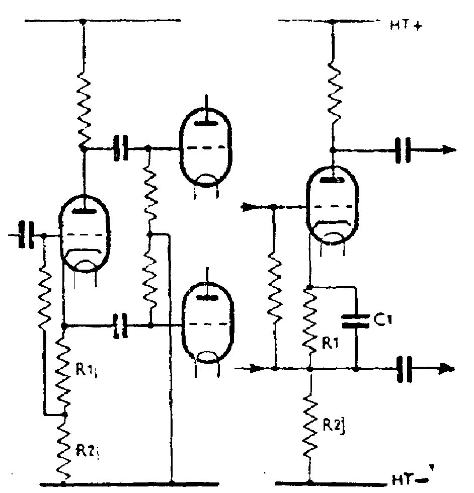
FIG. 13
The outputs are taken from the triode, one from its anode, the other from its cathode, which are exactly 180-degree out of phase with each other, by coupling capacitors connected to the grids of the push-pull output tubes (valves). As no by-pass capacitor is fitted from the cathode of the triode to chassis, very heavy negative feedback takes place, to the extent where the gain of the tube (valve) is reduced to unity. This is usually of no account because ample drive is available from the first AF amplifier, and the circuit gives excellent fidelity with very low distortion. However, if there is no preceding AF amplifier, as in a short superhet, the phase splitter may be made to give normal gain by feeding the incoming signal between grid and cathode instead of between grid and earth, and using a cathode by pass capacitor, as seen in the right-hand diagram of FIG. 1. The price is the loss of the special advantages of the original splitter plus a greater tendency for hum to occur. In addition the input to the triode is more difficult to arrange, in particular the use of a gramophone pick-up, due to it being impossible to earth one side; predictably Ultra Ltd, with its predilection for short superhets, was one of the few makers to use the method.
Another type of phase splitter known as the ‘paraphase’ uses two triodes wired as resistance- capacity amplifiers, of which one (V1 in FIG. 14) receives its input from the first AF amplifier or directly from the detector as the case may be.
This tubes (valves) gives the usual amount of gain and drives the grid of one of the output tubes (valves) (V2). The grid return resistor for this is made up of R2 and R1 in series; the latter is set to give a small percentage of the total signal to the grid of VP, the paraphase valve. Its anode delivers an opposite phase signal to the grid of the other output valve, V3. It is essential that the level of signal reaching V3 is the same as that delivered to V2, so the values of the various resistors have to be chosen with great care, and to maintain their accuracy, to ensure that the overall gain of V2 is unity; close tolerance types are therefore essential. The advantage of the paraphase is that it does give useful gain without the drawbacks of the modified concertina, including near immunity to hum.
Various other types of phase splitter have been used by different manufacturers, most of them based on the paraphase type but using all sorts of devices to enable the total tubes (valves) count to be reduced. These are too many in number and too complex to be discussed here and the relevant service information is essential for anyone tackling faults on them. Fortunately they did not achieve great popularity, most firms preferring to stick to the tried and true methods. A completely different alternative, found particularly in certain sets made by EMI just after the Second World War, was the use of a 1:1 auto-transformer as a phase-reverser following the first AF amplifier.
Better tone control systems
For most pre-war sets (and a lot of those made after 1945) the term ‘tone control’ means no more than a way of reducing the treble response of the set. Although the term high fidelity had originated early in the 1930s, listeners in general preferred what came to be called in the trade the ‘mellow bellow’ of a good wooden cabinet reproducing the lower and middle registers vigorously with not much more than a trace of top notes. This was regrettable since in those days AM broadcasts were capable of giving more extended high note coverage than is the case today. It may not generally be realised that 78 r.p.m. gramophone records were even better, especially when Decca introduced its Full Frequency Range Response (ffrr) records in 1947. Good quality radio-gramophones produced by such firms as EMI, the Radio-Gramophone Development Co. (RGD) and Decca itself incorporated sophisticated tone-control systems worthy of the music that was obtainable, most of which were based on the use of negative feedback (but sometimes with an element of positive feed back as well). Instead of the simple ‘top-cut’ control, such sets gave the listener the facility to vary up and down as required both the bass and treble response. It is sad to reflect that, apart from true music lovers, owners of these sets probably left the bass control right up and the treble control right down.

FIG. 14 Paraphase phase splitter

FIG. 15 Tone control system with both treble (R1) and bass (R2) controls
Band-spread short wave tuning
Starting in the mid-1930s there was a great upsurge in the number of listeners wanting to tune into distant short wave stations, especially to receive American commercial music and comedy programs sent out on MW and SW simultaneously. Then, as the political situation in Europe worsened, people wanted to learn what America thought about it via their news broadcasts. The trouble was that even with the aid of a ‘magic eye’ it was tricky to tune in to any particular SW station simply because there were so many of them. The main SW band of 16 m—52 m covers something like l2mHz of air space with a potential to carry over 1300 radio channels spaced 9 kHz apart. In fact the SW band was subdivided into smaller ones each about 1 mHz wide, known as the 16m band, 19m band, 25 m band, 31 m band, 40 m band and 49 m band. Each of these could accommodate over 100 stations within perhaps half an inch of pointer movement on a radio dial; no wonder it was difficult to select the one you wanted. The radio manufacturers got over this by the introduction of band-spread tuning, which means exactly what it says: by using special coils and a small-value tuning capacitor each SW band occupies the full length of the dial, making tuning in stations as easy as on MW or LW. Pye Ltd in particular took up this idea with enthusiasm, first with its ‘International’ model of 1939 and then with a number of models through the late 1940s and the 1950s. Murphy Ltd also made a notable band-spread set which was good enough to be used at the BBC’s official listening station through the Second World War along with sophisticated military ‘communication’ receivers.
The double superhet
This other approach to SW listening has, as the name suggests, two frequency changer sections, the first of which is broadly tuned and produces an IF of 1600 kHz or more with a wide bandwidth of several hundred kHz. When tuned to, say, the 49 m band virtually all its stations appear in the IF. If amplified and detected this would produce a useless jumble of sounds but the secondary winding of the wide-band IFT acts as the grid tuning coil for the second frequency changer, which can select any desired station and pass it on at a standard IF of about 450 kHz. The IFTs for this frequency have the usual frequency response and are followed by a normal detector, AF and output stage.
The extra tube (valve) used in the double superhet give it more gain than an ordinary type and in addition help to reduce the signal to noise ratio, that is, the ability of the set to bring in a station as clearly as possible and to suppress background noise. Murphy Ltd made one of the first domestic double superhets. Model A36, just before the Second World War.
‘Television sound’
When the BBC high definition TV service commenced in 1937 several radio manufacturers added an extra, what was then called ultra-short, wave band to enable listeners to take advantage of the high quality sound radiated by Alexandra Palace on 41.5 mHz (it was also possible, of course, that this might arouse enough interest to lead to sales of actual television receivers). The facility is only of academic interest now, with TV long having departed to UHF, but it does give an interesting insight into how perfectly standard tubes (valves) could be made to work at frequencies far higher than their manufacturers ever considered possible.