What you need to know about tubes (valves) (part 1)
The simplest kind of valve, and the one that inspired the name, is the two-electrode type or diode (from the Greek dis, twice + electrode). In essence this consists of a filament, not unlike that of an electric lamp, around which is mounted a metal plate in the form of a cylinder or flat box, the whole being sealed into a glass bulb and evacuated. When the filament is lighted by means of a battery or a source of low voltage AC it emits negatively charged particles of electricity called electrons. If another battery of, say, about 30V is connected with its negative terminal to one side of the filament and its positive to the metal plate a current will pass between them; however, if the battery connections are reversed no current will flow. This one-way action mimics that of a mechanical one- way valve, hence the name given to the diode, which at one time was the only type available.
The correct name for the two parts of the diode are cathode (from the Greek, a way up) for the filament and anode (also from the Greek, a way down) for the plate. In practice, though, the term cathode is not used for tubes (valves) with simple filaments, otherwise known as directly heated tubes (valves), which require a pure DC to power them. In practice this usually meant accumulators, so early filaments tended to be made suitable for 2V, 4V or 6V for operation either from one, two or three cells. By the 1930s the standard voltage was 2V and nearly all the battery radio sets likely to be encountered were for use with a single accumulator. This is known as the low tension (LT) battery.
AC is not suitable for filaments because they would dim 100 times per second at the zero point of each cycle. Although this is imperceptible to the eye, the effect would be to impose a 50 Hz hum on the output from the valve. Nor is the type of current that used to be obtained from DC mains altogether suitable since, as we saw earlier, it contains a certain amount of AC ripple which again would impose hum on the output. After a number of false starts the problem finally was solved in the late 1920s when tubes (valves) specifically designed for operating on low voltage AC transformed down from the house mains were developed. In these tubes (valves) the filament or heater is contained in a metal tube, from which it is electrically insulated, made of a material which emits electrons when heated and is unaffected by the 50 Hz variation in voltage. The term ‘cathode’ was brought back into use for this new electrode. The same principle was used later for tubes (valves) intended for use on DC mains and subsequently for either AC or DC operation. We shall look at mains tubes (valves) more closely later but for the moment we will confine ourselves to directly heated tubes (valves).

FIG. 1
The term anode instead of plate also was not generally adopted in Britain for many years, and for a long time tubes (valves) and tubes (valves) holders were marked with a letter ‘P’ to indicate Plate. This term survived right through the tubes (valves) age in the USA. Therefore, when you read any literature to do with tubes (valves) you may assume that anode and plate are synonymous.
If an AC voltage is applied to the anode of a diode only the positive half-cycles will be able to pass through it, producing at the filament a positive DC voltage pulsating at a rate equivalent to the incoming frequency. When the latter is high the half-cycles are so closely packed that the effect is almost equivalent to pure DC. Note though that the DC cathode voltage is equivalent to the peak voltage of the AC input and thus is 1.414 times that of its RMS value (or at least in theory; in practice the actual voltage may be somewhat less).
Although the diode is a useful device it lacks the ability to amplify. This problem was solved when the three-electrode tubes (valves) or triode (from the Greek treis = three) was developed. In this a new electrode consisting of a fine wire mesh called a grid is inserted between the filament and anode. Another battery, this time of between about 50 V and 150V and known as the high tension (HT) battery, is connected with its negative terminal to one side of the filament and its positive to the anode (AC is unsuitable in both battery and mains triodes). This attracts to the anode electrons emitted from the filament, which have to pass through the grid to reach it. If a small negative voltage is applied to the latter with respect to the filament the electron flow is impeded. This in turn reduces the anode current flowing through the valve, and increasing the negative voltage on the grid will reduce the current still more until it reaches zero, or what is called the cut-off point. Conversely, making the grid positive with respect to the filament increases the anode current. If an AC voltage is applied to the grid the anode current will swing up and down in sympathy with the positive and negative cycles of the input but — and this is the important part — only a very small change in grid voltage is required to give a relatively large change in anode current. If the voltage to the anode is supplied via a resistor there will be a varying drop across the latter in accord with the variations in anode current, and this voltage change will follow that at the grid but will be a much magnified version; in other words, the triode is able to amplify voltages. It is this property that made possible the introduction of broad casting and of radio receivers as we know them.
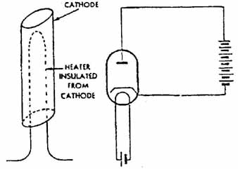
FIG. 2 Above left: diagrammatic representation of a cathode. Above right:
how the cathode takes the place of the filament in a circuit.
Tube (valve)characteristics
Each tube (valve) has a set of what are called characteristics which determine how it performs and for what job it is best suited. In the early days, characteristics were likely to be more a matter of luck than judgment and it would have been difficult to find any two tubes (valves) that were identical in this respect. As tubes (valves) making became a more scientific process it became possible to evolve a set of standards which enabled characteristics to be predicted with accuracy and to be maintained over long production runs. Note that although the filament or heater voltage and current of a valve, which may be in various combinations, are quoted for reference, they are not included in the list of characteristics. Those which are of importance to anyone engaged in repairing rather than designing radio sets are as follows:
Anode voltage (symbol Va).
Anode current (I_a) at that particular voltage.
Grid bias voltage (-Vg) (this is a standing negative voltage applied to the grid, the purpose of which will be explained a little later).
Mutual conductance (g_m) or ‘slope’.
Anode resistance (r_a).
Amplification factor, for which the Greek letter u was chosen as an abbreviation. It should not be confused with the first two letters of mutual conductance! The other use of u as a sub-multiple is regrettable in a way, but the context in which it is used will normally prevent confusion.
Optimum load (R_a — note upper case to distinguish it from anode resistance). This is the value of impedance or resistance to be placed in the anode circuit to obtain the best all-round output.
The mutual conductance of any tubes (valves) is a direct measure of its sensitivity and is calculated by dividing the change in ‘a brought about by a certain change in Vg. It may be displayed as a graph called a characteristic curve in which the change of anode current at a given voltage is plotted with respect to various voltages on the grid. In FIG. 3 the anode voltage is taken as 150V and the grid voltage as between —5V and +2 V. Starting at the bottom left-hand corner with a grid voltage of —5 V, the anode current is zero, or at the cut-off point of the tubes (valves) and no further increase in negative voltage will make any difference.
However, as the grid voltage is reduced to —4 V a small anode current of about 0.25 mA begins to flow. A further reduction to —3 V increases the anode current to 1 mA. From this point a smooth increase in ‘a is recorded until the grid voltage reaches 0 V; as it goes into positive values the ‘a rises more quickly and at +2 V reaches more than 6mA. In practice care is taken to avoid the grid becoming positive since the sustained high anode current that would result would damage the valve.
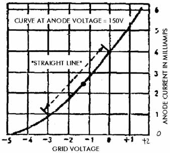
FIG. 3 Grid Voltage vs. Anode Current
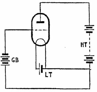
FIG. 4 Showing how a battery is used to place a standing negative ‘bias’
on a valve. (GB = grid bias, LT = low tension, HT = high tension, tension itself
means the same as voltage)
Look again at the section of the graph which lies between —3V and 0V on the grid and between 1 mA and 4 mA ‘a’ and indicated by a dotted line. This is called the ‘straight-line’ part of the curve and when a tubes (valves) is working it gives its best performance when the ‘a is restricted to these limits. For this reason a standing grid voltage or bias is applied to maintain the ‘a at the mid-point of the curve when the tube (valve) is at rest. When we speak of the input voltage to the grid as swinging between negative and positive the true variation is between more negative and less negative.
The rate at which the ‘a increases with a reduction of negative voltage on the grid determines the angle of the ‘a Vg curve. In a tube (valve) of low sensitivity the curve will rise only slowly, whilst in a highly sensitive tubes (valves) it will climb sharply. For this reason a tube (valve) possessing good sensitivity, or high mutual conductance, is sometimes referred to as a ‘steep-slope’ type.
It is important to note that mutual conductance is in itself not a measure of the amplification factor of the valve. This is determined by another set of figures. If the bias voltage on the grid is made less negative by a very small amount the ‘a will increase slightly (for this test it is assumed that there is zero resistance between the HT supply and the anode).
If the Va is then reduced gradually a point will be reached where the ‘a is the same as before the grid voltage was changed. Dividing the change in V_a necessary to achieve this by the change in -Vg gives the amplification factor or u.
Depending on the type of tubes (valves) p. may be anything from between about 5 up to 125. Although this gives us an idea of by how much the tubes (valves) is likely to amplify a signal applied to the grid, it is not what will actually be obtained in practice. It was mentioned above that p. is calculated with no resistance between HT+ and anode, but in real life there always is some. When Vg is changed and the ‘a alters it will bring about a change in Va as well, which upsets the calculations. It was thus customary for tubes (valves) manufacturers to work out a realistic stage gain figure that might be expected under typical operating conditions.
Anode resistance, by which is meant the actual resistance in the tubes (valves) to passing current, is not easily pinned down. It can be calculated as a DC value of ohms by dividing the Va by ‘a, but this will only hold good for one particular combination of the two. Valves are normally operated with alternating voltages on the grid so a more useful figure is obtained by taking the difference in Va as against ‘a on the straight-line part of the characteristic curve. This figure, written as r_a, is referred to as the ‘AC resistance’ or impedance of the valve. As a generalization, high impedance tubes (valves) take less anode current but are likely to have a high p., whilst medium and low impedance types take more anode current and probably have a fairly low p.. Note, though, that either may have large or small values of g_m. There is a certain amount of correlation between g_m, u. and r_a, so that if any two are known the third may be calculated. For instance, multiplying gm by r_a gives p., whilst dividing u by r_a gives g_m.
Optimum load. When a tubes (valves) is operated with an anode load consisting of a resistor the optimum Ra is between two and three times the Ta; there is no easy way to calculate this exactly and it is best to use the value suggested in the tubes (valves) maker’s datasheet.
If the anode load takes the form of an impedance, such as the primary of a transformer, the manufacturer’s recommendation has again to be followed. This subject will be covered in more detail in the next section.