Figure 1. 7400 I.C. logic figure.
| Home | Audio mag. | Stereo Review mag. | High Fidelity mag. | AE/AA mag. |
The 7400 Series IC's are one of the most freely obtainable, inexpensive and versatile range of devices available to the home constructor.
The author of this guide, Mr. R.N. Soar, has compiled 50 interesting and useful circuits using this range of devices, covering many different aspects of electronics.
Ingenuity is the only limitation to the uses that this incredible family of IC's can be put to and it is hoped that the 50 circuits contained in this guide will not only prove useful in themselves but, also, serve to fire the imagination of the reader to develop his own applications.
An essential addition to the library of all those interested in electronics be they amateur or professional.
CONTENTS
Introduction [this page; see below TOC]
Circuit 1. Inverter or NOT Gate
Circuit 5. Logic Level Indicator
Circuit 6. Bistable Latch (S.R. Flip -Flop)
Circuit 7. S.R. Flip -Flop Rectangular Wave Generator
Circuit 8. Switch Contact Bounce Eliminator
Circuit 10. S.R. Flip -Flop Memory
Circuit 11. Clock Controlled Flip -Flop
Circuit 12. High Speed Pulse Indicator and Detector
Circuit 14. Low Frequency Audio Oscillator
Circuit 18. Low Hysteresis Schmitt Trigger
Circuit 19. Fundamental Frequency Crystal Oscillator
Circuit 21. Two Bit Decoder (Simplified)
Circuit 22. Photo Sensitive Latching
Circuit 23. Twin Tone Audio Oscillator
Circuit 24. Crystal Clock Oscillator
Circuit 25. Switched Oscillator
Circuit 28. Reference Frequency Switch
Circuit 29. Switch Contact Bounce Eliminator
Circuit 30. Two Bit Data Check
Circuit 32. NOR Gate Half Adder
Circuit 33. NOR Gate Full Adder
Circuit 34. Simple Signal Injector
Circuit 35. Simple Amplifier 51
Circuit 38. Divide by Six 7490 Circuit
Circuit 39. 74121 Pulse Generator
Circuit 44. 1 Microsecond Delay Circuit
Circuit 45. Simple 5v Power Supply and 50hz Square Wave Generator
Circuit 48. Divide by 4 In Quadrature Outputs Circuit
Circuit 49. Experimenters V.C.O.
List of I.C. Types Used [this page; see below TOC]
Acknowledgements [this page; see below TOC]
INTRODUCTION
This guide contains 50 circuits using the 7400 and other 7400 series I.C.s. It is based on the 1979 book shown above.
The ultra low cost of I.C.s now means that the limitation on building circuits is not the cost of the active devices but the cost of associated capacitors, resistors and connecting wire.
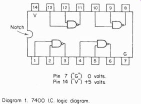
The I.C.s 7400 and the 7413 are 14 -pin D.I.L. I.C.s, i.e. "14 pin Dual In Line Integrated Circuits", pin 14 is the power connection or V+ and pin 7 is the power supply negative, ground or 0 -volt connection. The power connections to pins 14 and 7 are not included on the figures to simplify the drawing but don't forget to wire them up, otherwise the circuit won't work! The circuits all function from a 4 1/2 -volt or 6 -volt battery supply although the nominal voltage is 5 volts. A mains powered 5 -volt stabilized supply is available from several sources. The savings on costs as against using batteries are vast.
Although some bargain price 7400 I.C.s are sold as "below standard" please remember that the standards set are very high. Part functional I.C.s are also available at very low cost.
The 7400 is a four -gate I.C. (see figure 1), but many circuits use only 2 or 3 gates so that a part functional I.C. can be used for these.
The four gates of a 7400 are identical:
Gate A pins 1,2 inputs, pin 3 output Gate B pins 4,5 inputs, pin 6 output Gate C pins 10,9 inputs, pin 8 output Gate D pins 13,12 inputs, pin 11 output The circuit figure may show an oscillator using gates A and B but there is no reason why the oscillator cannot be built using gates A and C, B and C or C and D if the other gates are non-functional.
For permanent use the circuits can be soldered on 0.1" matrix veroboard. A small bit 15W soldering iron is essential.
Figure 1. 7400 I.C. logic figure.
Figure 1 shows the logic circuit of the 7400 I.C.
Figure 2 shows the logic symbol for one gate, each gate is a "Two Input NAND Gate".
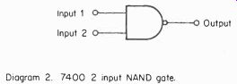
Figure 2. 7400 2 input NAND gate.
The circuit figure of a single gate is shown in Fig. 3. The 7400 is a T.T.L. logic I.C., i.e. it uses "Transistor-Transistor Logic". Each gate uses 4 transistors, each 7400 contains 4 x 4= 16 transistors.
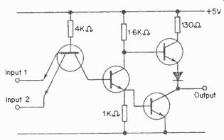
Figure 3. 2 input NAND gate internal circuit.
The logic gates have two states, based on the binary system, 1 or "High" nominally 4 volts and 0 (zero) or "Low" nominally 0 volts. If a gate lead is unconnected this is equivalent to a 1 input, i.e. an unconnected gate lead is at "high" level. If a gate input lead is "grounded', i.e. connected to 0 volts the input is then 0.
The NAND gate is a "NOT AND" gate if both inputs (and function) are at logic 1, output is NOT 1. NOT 1 corresponds to zero, i.e. output is logic 0. If both inputs are logic 0, output is logic not 0, i.e. logic 1. It may be less easy to under stand why the output is 1 when inputs are 0 and 1 or 1 and 0.
However, consider it this way. The output with 2 inputs of 0 is 1. For a change of state an AND function has to take place, i.e. both inputs have to change for a change of state - this only occurs when both inputs change from 0 to 1. The 7400 gates are 2 input NAND gates but 3 input NAND gates 7410 I.C., 4 input NAND gales 7420 and even an 8 input NAND gate 7430 are available for the 7430 and its 8 input gate to change state each one of the 8 inputs must be either 1 or 0.
If the 8 inputs to the 7430 are 1,1,1,1,1,1,1,0 the output is 1. The change of state does not take place until all 8 inputs are the same when the final input changes from 0 to 1 the output then changes to 0. The idea of a "change of state" is an important one in understanding the function of logic circuits.
The number of pins on the logic I.C.s is usually 14 or 16. A 7400 has four NAND gates, 3 connections each plus power supply connections = 14. The larger number of inputs for 3 input NAND gates, 4 input NAND gates and the 8 input NAND gate requiring the use of more connections for each gate means that the I.C. 7410 contains only three 3 -input NAND gates. "Triple 3 input NAND gate" describes the 7410.
The I.C. 7420 contains only two 4 -input NAND gates - "Dual 4 input NAND gate" - and the I.C. 7430 contains only one 8 -input NAND gate.
Although the 7400 contains NAND gates by connecting up the NAND gates in various ways, it is possible to form other types of gate:
(1) an inverter or "NOT" gate (2) an AND gate (3) an OR gate (4) NOR gate.
The computer manufacturers use I.C.s specially made for the job. The 7402 is similar to the 7400 but contains four NOR gates. Just as NAND is "NOT AND", NOR is "NOT OR".
The 7400 is a very versatile I.C. as can be seen by the number of circuits in the applications manual. To help understand the function of a NAND gate a TRUTH table is shown for a 2 input NAND gate. Similar truth tables can be constituted for any logic gate. The truth table for an 8 input gate such as the 7430 is more complicated.
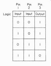
--------- 2 input NAND gate truth table.
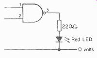
Figure 4
7400 Test Circuit (see figure 4)
With pins 1 and 2 unconnected the logic levels are inputs 1, 1, output 0. Connect pin 1 to 0 volts. Inputs are 1, 0, output 1 LED glows. Connect pin 2 to 0 volts (pin 1 disconnected).
Inputs are 0, 1, output 1 LED glows. Connect pins 1 and 2 to 0 volts. Inputs are 0, 0, output 1 LED glows.
The red LED (light emitting diode) glows to indicate logic level 1. If LED is not illuminated this indicates logic level 0.
The test can be repeated with gates B, C and D.
Note to constructors: all the circuits shown use 14W 5% resistors - all electrolytic capacitors are 16 -volt working.
If a circuit is not working check the connections -- a faulty I.C. is far less likely than faulty wiring.
ACKNOWLEDGEMENTS
The author would like to thank the following companies for help and information given while preparing the material for this guide.
Codespeed Ltd.
Concept Electronics Ltd.
National Semiconductor Co. Ltd.
P.B. Electronics ( Scotland) Ltd.
Vero Electronics Ltd.
OTHER BOOKS OF INTEREST
BP36: 50 CIRCUITS USING GERMANIUM SILICON AND ZENER DIODES
AUTHOR: R.N. SOAR
PRICE: 75p ISBN: 0 85934 039 2
64 Pages
Approx. Size: 180 x 105 mm
Contains 50 interesting and useful circuits and applications, covering many different branches of electronics, using one of the most simple and inexpensive of components - the diode. Includes the use of germanium and silicon signal diodes, silicon rectifier diodes and zener diodes, etc. A valuable addition to the library of both the beginner and more advanced enthusiast alike.
BP42: 50 SIMPLE L.E.D. CIRCUITS
AUTHOR: R.N. SOAR
PRICE: 75p ISBN: 0 85934 043 4
64 Pages
Approx. Size: 180 x 105 mm
The author of this guide, Mr. R.N. Soar, has compiled 50 interesting and useful circuits and applications, covering many different branches of electronics, using one of the most inexpensive and freely available components - the Light Emitting Diode (L.E.D.). Also includes circuits for the 707 Common Anode Display. A useful book for the library of both beginner and more advanced enthusiast alike. Companion volume to book No. BP36 - 50 CIRCUITS USING GERMANIUM, SILICON & ZENER DIODES by the same author.
Please note overleaf is a list of other titles that are available in our range of Radio and Electronics Books.
These should be available from all good Booksellers, Radio Component Dealers and Mail Order Companies.
However, should you experience difficulty in obtaining any title in your area, then please write directly to the publisher enclosing payment to cover the cost of the book plus adequate postage.
If you would like a complete catalog of all our Radio and Electronics Books then please send a Stamped Addressed Envelope to:
BERNARD BABANI (publishing) LTD
THE GRAMPIANS SHEPHERDS BUSH ROAD
LONDON W6 7NF ENGLAND
+++++++++++
BP1 First Book of Transistor Equivalents and Substitutes Sop
BP2 handbook of Radio. TV and Ind. 8 Transmitting Tube 8 Valve Equiv. 60p 6P6 Engineers and Machinists Reference Tables 50p BP7 Radio and Electronic Colour Codes and Data Chart 25p Bell Practical Transistor Novelty Circuits 40p BP14 Second Book of Transistor Equivalents 1.10p BP22 79 Electronic Novelty Circuits 75p BP23 First Book of Practical Electronic Projects 75p BP24 52 Projects using IC741 95p BP25 How to Build Your Own Electronic and Quartz Controlled Watches 8 Clocks 85p BP26 Radio Antenna Handbook for Long Distance Reception 8 Transmission 85p BP27 Giant Chart of Radio Electronic Semiconductor 8 Logic Symbols 60p BP28 Resistor Selection Handbook (International Edition) 60p BP29 Major Solid State Audio HI-Fi Construction Projects 85p BP30 Two Transistor Electronic Projects 850 BP31 Practical Electrical Re -wiring 8 Repairs 85p BP32 How to Build Your Own Metal and Treasure Locators 1.00p BP33 Electronic Calculator Users Handbook 95p BP34 Practical Repair 8 Renovation of Colour TVs 95p BP35 Handbook of IC Audio Preamplifier 8 Power Amplifier Construction 95p BP36 50 Circuits Using Germanium, Silicon and Zener Diodes 75p BP37 50 Projects Using Relays. SCR's and TRIAC's 1.10p BP38 Fun 8 Games with your Electronic Calculator 75p BP39 50 (FET) Field Effect Transistor Projects 1.25p BP40 Digital IC Equivalents and Pin Connections 2.50p BP41 Linear IC Equivalents and Pin Connections 2.75p BP42 50 Simple L.E.D. Circuits 7 :la BP43 How to make Walkie-Talkies 1.25p BP44 IC 555 Projects 1.45p BP45 Projects on Opto-Electronics 1.25p BP46 Radio Circuits using IC's 1.35p BP47 Mobile Discotheque Handbook 1.35p BP48 Electronic Projects for Beginners 1.35p BP49 Popular Electronic Protects 1.45p BP50 IC LM3900 Projects 1.35p BP51 Electronic Music and Creative Tape Recording 1.25p BP52 Long Distance Television Reception (TV-DX1 for the Enthusiast 1.45p BP53 Practical Electronic Calculations and Formulae 2.25p BP54 Your Electronic Calculator and Your Money I.35p BP55 Radio Stations Guide 1.45p BP56 Electronic Security Devices 1.45p BP57 How to Build your own Solid Stale Oscilloscope 1.50p BP58 50 Circuits using 7400 Series IC's 1.35p BP59 Second Book of CMOS IC Projects I.50p BP6O Practical Construction of Pre-Amps. Tone Controls. Filters and Attenuators 1 45p BP61 Beginners Guide to Digital Techniques 95p 100 A Comprehensive Radio Valve Guide - Book I oup 121 A Comprehensive Radio Valve Guide - Book 2 40p 126 Boys Book of Crystal Sets 259 139 How to Make Aerials for TV (Band 1-2-3) 25ta 143 A Comprehensive Radio Valve Guide - Book 3 40p 157 A Comprehensive Radio Valve Guide - Book 4 40p 160 Coil Design and Construction Manual 75p 178 A Comprehensive Radio Valve Guide - Book 5 40p 196 AF-RF Reactance - Frequency Chart for Constructors 15p 200 Handbook of Practical Electronic Musical Novelties 50p 201 Practical Transistorized Novelties for Hi-Fi Enthusiasts 35p 202 Handbook of Integrated Circuits (IC's) Equivalents and Substitutes i 00o 203 IC's and Transistor Gadgets Construction Handbook 60p 205 First Book of Hi-Fi Loudspeaker Enclosures Thy 206 Practical Transistor Circuits for Modern Test Equipment 60p 207 Practical Electronic Science Projects 75p 208 Practical Stereo and Cluadrophony Handbook 75p 210 The Complete Car Radio Manual 1.00p 211 First Book of Diode Characteristics Equivalents and Substitutes 95p 213 Electronic Circuits for Model Railways 1.00p 214 Audio Enthusiasts Handbook 85p 215 Shortwave Circuits and Gear for Experimenters and Radio Hams 85p 216 Electronic Gadgets and Games 1.00p 217 Solid State Power Supply Handbook 85p 218 Build Your Own Electronic Experimenters Laboratory 85p 219 Solid State Novelty Projects 850 220 Build Your Own Solid State Hi-Fi and Audio Accessories 85p 221 28 Tested Transistor Projects 95p 222 Solid State Short Wave Receivers for Beginners 95p 223 50 Projects using IC CA3130 95p 224 50 CMOS IC Projects 95p 225 A Practical Introduction to Digital ICS 95p 226 How to Build Advanced Short Wave Receivers 1.20p 227 Beginners Guide to Building Electronic Projects 1.25p 228 Essential Theory for the Electronics Hobbyist 1.25p RCC Resistor Colour Code Disc Calculator 10p
LIST OF I.C. TYPES USED
7400 Quad 2 input NAND
7401 Quad 2 input NAND open collector
7402 Quad 2 input NOR
7404 Flex inverter (NOT)
7408 Quad 2 input AND, 7413 Dual 4 input NAND Schmitt trigger
7473 Dual Master Slave J.K. Flip-Flop
*7476 Dual Master Slave J.K. Flip -Flop
7490 Decade Counter
7493 4 -bit Binary Counter
74121 Monostable Flip -Flop
* 16 -pin type. The remainder are 14 -pin D.I.L.
Also see:
A Practical Introduction to Digital IC's (1977)