The troubleshooting process can be speeded up greatly if you know what parts and what defects in them are likely to cause certain operational problems. For example, if the sound from a radio set is distorted, only a few defects can cause this. If you know what they are, then you’ll know where to begin looking for the trouble and what measurements to make. This Section provides a handy guide to the problems of weak reception, distorted sound, intermittent operation, hum, and noise. The information in this Section should help you get your collectible radios operating shipshape in record time.
The best way to begin troubleshooting is to inspect the receiver thoroughly. See that the power plug is in place, examine the fuses and turn on the receiver. Look and smell for evidence of burning. See that all tubes are in the right sockets. Note whether the set has been burning or smoking. Burning can be the result of arcing from the chassis through the wire insulation, an overloaded resistor, or a shorted transformer winding. When a resistor becomes greatly overloaded and smokes it is usually because of a shorted filter or bypass capacitor, but the smoking can also be caused by a winding shorting to the chassis or to another winding.
TROUBLESHOOTING A WEAK RECEIVER
The procedure for troubleshooting a weak receiver is basically the same as that used for a dead receiver; that is, it is a matter of localizing the trouble by stages. But note this difference: When troubleshooting a dead set, you are not too concerned about the amount of output that results from a particular test, so long as there is an output; when troubleshooting a weak set, you may find it important to know the precise amount of output produced when a signal is injected into the stage. It is assumed that the tubes in the suspected stages have been tested before stage gain tests are made.
Before troubleshooting procedures are begun, some preliminary steps should be taken to insure that the defect is not an operating fault. Listed below are some checks that you can make before you begin troubleshooting.
— See that the receiver is tuned properly.
— Be sure that all switches are properly set.
— Check the line voltage to see that it has not dropped.
— Determine whether signals are weak on only one or more stations.
— Check the antenna to see that it is still connected.
Troubleshooting Without Stage Gain Data
It is usually possible to locate the trouble in a weak receiver without stage gain information. In such cases, a signal is injected into the various stages, the point being noted at which the signal input must be increased instead of decreased to produce the same output. For example, an audio signal from an AF signal generator applied to the plate of an audio amplifier produces a certain output from the receiver. When the same signal is applied to the input of the same stage, it should produce a stronger output than before—the signal generator output must be reduced to keep the output at the same level. If the generator output must be increased to produce the same output, the trouble is between the input and output of this stage.
Troubleshooting by Using Stage Gain Data
Sometimes it is almost impossible to determine whether a stage has the proper gain, either because it is normally low, or because the slight difference from normal output cannot be noticed. Then you must take detailed stage-gain measurements to determine which part of the receiver is not amplifying properly. To do this, the technical data for a receiver must specify the minimum and maximum signals required at certain points to produce a given output. It is important to set all controls and switches as the receiver manual recommends.
.As the tests progress toward the antenna section, there is less signal input required to produce the same output. This is because the signal is being amplified by passing through more stages. The output of the signal generator should be compared with the information in the radio manual. Readings that are out of limits by a small amount do not necessarily indicate that the receiver is not operating properly.
The gain of the individual stages of a receiver over a period of time will vary. If the difference is great and the receiver’s overall output is weak, the stage probably is at fault. When a stage lacks gain by a considerable amount, voltage and resistance checks might be necessary to locate the faults.
In the case of a weak receiver, the tubes should be checked before any other action is taken. Voltage and resistance measurements will show such faults as leaky bypass capacitors and resistors that have changed in value. These conditions can reduce the plate and screen-grid voltages to the extent that the output will decrease and cause the signals to become weak.
In FIG. 1, capacitor C603A can cause the above troubles in the plate circuit of first AF amplifier V601A and AF cathode follower V601B.
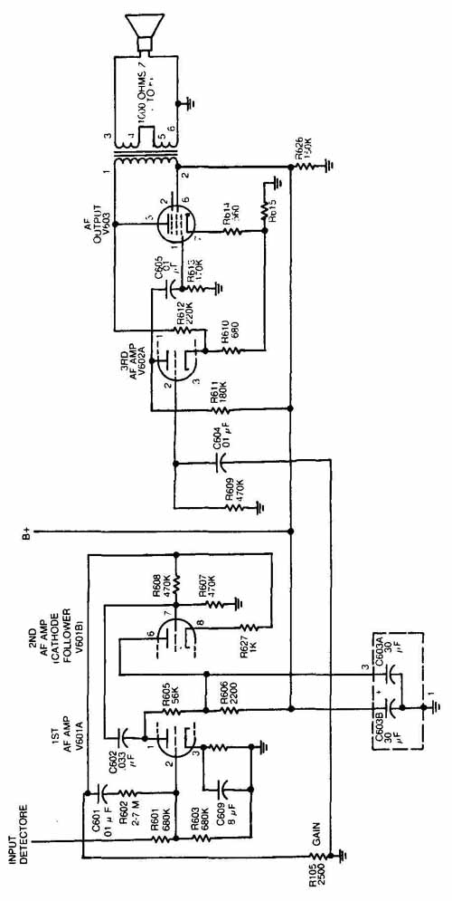
FIG. 1.
FIG. 2. Audio signal tracer.
An open bypass capacitor is hard to locate, because there is no telltale indication of its condition in the DC voltage and resistance readings. But there are other symptoms that can be detected.
• Capacitor C609 is the cathode bypass in V601A, the first IF amplifier. If C609 should open, there would be a signal voltage drop across cathode-biasing resistor R604, the voltage drop will cause degeneration and this in turn will reduce the output noticeably.
• If the cathode bypass in the first IF amplifier should open, the signal would be considerably weaker than it would have been in the case of C609. This is because any signal present in the IF section of a normally operating set is considerably weaker than it is in the AF section, and any loss occurring in the IF section is therefore the more noticeable.
An open coupling capacitor between stages usually will cause the output to drop to zero, but in the case of a very strong signal, the signal may get by the open capacitor and produce a weak output. However, signals other than the very strong ones will not get through with very much strength. Then you can consider the set weak.
TROUBLESHOOTING A DISTORTED RECEIVER
Only a few defects can cause distortion, and they can usually be identified by the sound of the receiver output. Distortion is present when the output signal is muffled or raspy, or does not sound as it should. The experienced troubleshooter can often tell from the sound just what type of distortion is present and what causes it. In most cases the distortion will be in the audio section. Distortion is usually caused by an upset in bias, or by overloading of a stage.
Types of Distortion
Frequency distortion occurs when all frequencies are not amplified to the same extent. For example, if the high and low audio frequencies originally were of the same strength, but in the output of the receiver the low frequency notes are reproduced louder than those of the high frequencies, frequency distortion is present.
Amplitude distortion is present when there is a change in the harmonic content of the signal after it passes through one or more stages. This type of distortion is the more bothersome because the signal sounds unpleasant, whereas frequency distortion is only a matter of some frequencies being stronger or weaker than others.
Common Causes of Distortion
• Leaky Coupling Capacitor. One of the most common causes of distortion is a leaky audio coupling capacitor such as C605 (Fig. 6 which couples the signal from the AF amplifier V602A to the AF output amplifier V603. If C605 becomes leaky, it will act as a resistor in series with grid resistor R613 and plate load R611. This series circuit is connected across the B+ line, making the grid end of R613 less negative than it was, or even positive. The tube now operates on the upper portion of the response curve, producing distortion.
• Gassy Tube. If the output tube V603 or any other tube becomes gassy, amplitude distortion will result. The bias will be reduced, and the grid might draw current and produce distortion.
• Other Causes. Other causes of distortion are misalignment, poor power supply filtering, warped speaker diaphragms, oscillation, excessive strength or input signals and interference from crosstalk.
Localizing Distortion
Localizing distortion is more difficult than troubleshooting a dead or weak receiver. Signal substitution can be used, but it is more convenient to use a form of signal tracing. Connect an antenna to the receiver input and connect a home-constructed audio signal tracer ( FIG. 2) to various points to determine where the trouble lies.
Assume that the output at the speaker terminals is distorted and the trouble is in the audio channel, which includes V602A and V603, and gain control R105. Connect the prods of the signal tracer to pin 5 of V603 and ground. If the signal is present at the output, the secondary of the output transformer is probably in good condition. Move the hot prod from pin 5 to pin 1 of V603.
If the output is not clear, the plate circuit of V602A is not operating properly, and the trouble could be in the input circuit of V602A.
A more positive method of detecting distortion is by using an oscilloscope and an audio signal generator. The equipment setup is shown in FIG. 3. Connect the signal generator to the vertical amplifier terminals of the oscilloscope by setting Si to position 1. This switch is set to position 2 to connect the oscilloscope across the plate load resistor of the stage being checked.
First, adjust the signal generator to 400 Hz. Set S1 to position 1 and adjust the oscilloscope frequency controls to produce on the screen two sine waves that look like those at Am FIG. 4. Adjust the oscilloscope controls to show clean sine waves. We are assuming at this point that trouble is not present. Compare the results with the patterns shown in FIG. 4.
Assume that the trouble has been isolated to the audio channel. Connect the output of the signal generator to V602 (first AF input) and set S1 to position 2. Connect the test probe to the plate (pin 5) of V603 and observe the waveform. If, for example, the waveform is unlike pattern A when the probe is connected to pin 5 of V603 and is like pattern A when the probe is connected to pin 2 of V602A, the distortion is between those two points. The patterns in B, C and D show the waveforms that will appear on the oscilloscope screen when there is distortion; they also indicate some of the causes of distortion.
Diagram D in FIG. 4 shows a distorted sine wave as it appears on an oscilloscope. When such a condition arises, the trouble may be in the AGC system (if present) because the AGC normally prevents overloading by keeping the output from all signals at a constant level.
TROUBLESHOOTING AN INTERMITTENT RECEIVER
A receiver is operating intermittently if from time to time it operates normally, but between times goes dead or develops any other type of trouble. Intermittent troubles include all types to which a receiver is subject, but they appear and disappear at irregular, or even regular, intervals. Such troubles are hard to trace, because they do not exist when the set is operating normally, and because the set may resume normal operation before you can finish testing it.
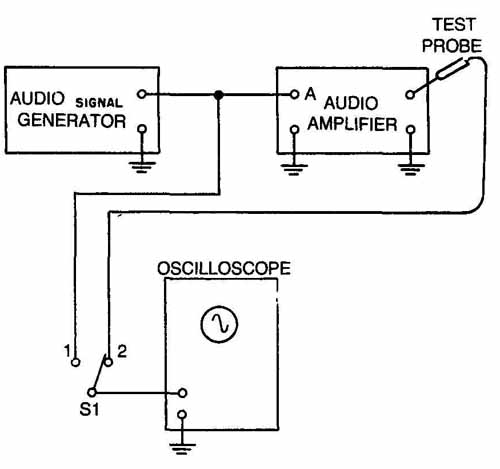
FIG. 3. Setup for checking distortion.
Causes of Intermittent Operation
• Capacitors. A frequent cause of intermittent operation is the haphazard opening and closing of a connection within a fixed capacitor. For example, the circuit would open if a pig-tailed lead pulled loose from the foil, and then a slight jarring of the set might cause the contact to be made again. That same effect might be caused by a sudden switching off and on of the voltage, if capacitor C604 in FIG. 1, which couples the audio from gain control R105 to the grid of AF amplifier V602A, should become intermittent, the signal level would vary up and down. If the opening and closing condition is at a rapid rate, the effect may appear as noise. If the screen-grid bypass in the IF amplifier should open and close at slow intervals, oscillations will occur. If it opens and closes in rapid succession, noise will be produced. Variable tuning capacitors can short intermittently because of dust, dirt, or other foreign particles becoming lodged in between the plates. The plating on the plates sometimes peels off in slivers which are often long enough to cause intermittent short circuits. The rotor wiping contacts may have improper spring tension or corrosion that could cause intermittent high-resistance contact to the capacitor frame. In very small variable capacitors, the plates have extremely close spacing; these plates can become bent and may short if the frame should warp because of heat or twisting of a subchassis. Small air capacitors, used as trimmers, and compression- type trimmers also collect dirt. The troubles will be the same as those in turning capacitors.
• Loose Connections. A loose connection in any portion of the set can cause intermittent operation.
• Resistors. Wire-wound resistors sometimes develop intermittent open circuits at the junction of the resistance wire and the terminals. Carbon resistors may develop opens, but they usually occur after the resistor becomes hot during a long period of operation. Some carbon resistors are insulated and have the resistance element in the form of a carbon rod in the center. The carbon rod can crack and cause intermittent operation.
• Tubes. Normally, in troubleshooting, the tubes are suspected first. If a tube is intermittent it may be normal when tested, and the test will be of no value. An intermittent tube can sometimes be found by tapping the suspected one.
== == ==
UNDISTORTED SINE WAVE OUTPUT
TOO HIGH BIAS OR TOO LOW PLATE OR SCREEN VOLTAGE
TOO LOW BIAS OR TOO HIGH PLATE OR SCREEN VOLTAGE
OVERLOADED STAGE, CAUSED BY TOO MUCH SIGNAL INPUT
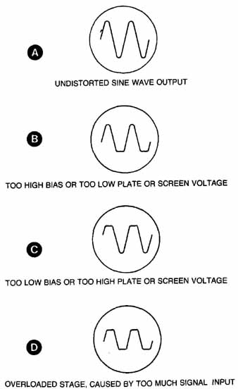
FIG. 4. Oscilloscope patterns showing distorted sine waves.
== == ==
Elements in a tube may expand because of heat, and short to other electrodes momentarily. The filament may expand and break. Then as it cools, the ends may come together again and current flows, producing normal results. .Depending on conditions, this may occur several times per minute for a particular tube.
• Inductors. RF and AC coils that carry DC are especially susceptible to intermittent opens. The form on which the coil is wound may expand from the heat and snap the winding. Moisture on the surface of the wire produces a chemical action which causes corrosion that will eat away the conductor. An arc may form and close the circuit momentarily; when the carbonized area breaks down, the circuit opens again.
• Potentiometers. Carbon volume or gain controls often have resistance strips that may become pitted because of wear. Only a small portion of the moving arm may be in contact with the strip, and a slight jarring of the set may break the contact momentarily. This condition will be pre sent especially in controls where DC current flows and arcing could occur.
• Solder Joints. Original solder joints often appear good to the eye, but under the surface there may be a looseness which could eventually cause intermittent operation. Technicians often introduce intermittent by poor soldering. Therefore, carefully examine all solder joints, particularly those that have been made during repairs.
Isolating Intermittent Troubles
• Audio Signal Substitution. Connect an electronic multimeter to the output circuit of the last IF amplifier. If during intermittent operation, the meter needle remains steady, the trouble is between the last IF amplifier and the audio output. An arcing in the power supply would have an effect on the output. If the trouble is traced to the audio section, the signal tracer that was used to trace distortion can be used by following the instructions given in Localizing Distortion. Rather than use the incoming signal from a transmitter in this procedure, however, it is better to apply an audio signal from a signal generator between the detector output and ground. This is because the signal from the generator will normally be at fixed amplitude, while the incoming signal may vary over a wide range. If the meter needle varies in step with the output signal, the intermittent condition is somewhere between the last IF amplifier and the antenna.
• RF Signal Substitution. The same procedure is used as in troubleshooting a dead set. A signal of the proper frequency is fed into the antenna jack with the antenna disconnected. A modulated or unmodulated signal can be used. If it is modulated, the signal can be heard in the speaker. If the signal is unmodulated, a VTVM connected across the detector load will indicate an output. When the set is intermittent, the trouble will show up as variations on the meter. Move the signal generator lead to the RF amplifier grid, lithe meter needle is now steady, the intermittent is between the RF amplifier grid and the antenna jack. If the output is still intermittent, the trouble is between the signal generator and the detector load. Move the signal generator output to the grid or the mixer. If the meter needle does not fluctuate in step with the intermittent signals, the trouble is between this point and the RF amplifier grid. If the meter needle follows the variations, the trouble is between the mixer grid and the detector load. This procedure is used to localize the defective stage, working toward the meter connection.
• Forcing Troubles to Reappear. There are times when the intermittent condition does not reappear for hours or even days. Often it can be made to reappear by placing a cardboard box over the receiver to concentrate the heat. This trick works best when the condition is caused by shorts or opens resulting from heat under the chassis. If the receiver is sensitive to jarring, rap the chassis at several points to make the intermittent reappear.
If one end of the chassis seems more sensitive to rapping, the trouble is probably, though not necessarily, at that end. Moving resistors and capacitors around with an insulated prod will often reveal poor contact in the components. If there is a sharp disappearance of the signal or a sudden change in noise, move the wiring around with the prod. Do not move the wires too far out of place, as this may cause other troubles. You can often find poor solder connections by wiggling the wiring at the sockets and other terminals.
The chassis may seem to be equally sensitive to jarring at all points. It is then necessary to keep prodding around, stage by stage, until the bad point is found.
Certain components will open intermittently during line voltage surges and will later be restored to normal. Remove and replace tubes one at a time. If the receiver becomes insensitive to tapping when a particular tube is removed, the trouble is in that stage or a stage closer to the antenna.
TROUBLESHOOTING A RECEIVER FOR HUM
Before the receiver can be freed of hum, it is first necessary to know what hum is and how to recognize it. The experienced radio repairer recognizes it as a steady low-pitched sound. Hum is produced by power line AC variations and is usually 60 to 120 hertz. It is a tone that has a constant amplitude and is of one frequency. This distinguishes it from noise, which consists of an unpleasing sound of many random frequencies and is constantly changing in amplitude. Hum can also be regarded as a low-frequency audio voltage. In this receiver, as in most other AC receivers, the hum will have a frequency of 60 to 123 hertz.
Hum may develop directly in the audio frequency section of a receiver because of:
— Inadequate filtering in the power supply.
— Stray coupling from the AC power leads.
— Short circuit between the heater and cathode of a vacuum tube.
— The signal present in the RF and IF circuits being modulated by the hum.
Causes of Hum
• Filter Capacitors. The most likely cause of hum in any AC receiver is an open filter capacitor. The capacitors are in the filter circuit for removing the hum from the output of the rectifiers. Capacitors C1 and C2 ( FIG. 5) are examples of filter capacitors. If either capacitor should open, the hum level would rise considerably. The schematic diagram shows that C1 and C2 are mounted in the same can. If leakage should develop between the two capacitors, the result would be similar to connecting a resistor across choke L2. This would reduce the effectiveness of the choke and cause a ripple in the output of the filter, producing hum. Excessive DC can be forced through choke L1 if filter capacitor C1 becomes leaky. The excessive DC through the choke causes core saturation, which lowers the inductance, and makes the choke less effective as a filter. These last two examples show that the hum is apparently caused by the choke, but the actual trouble is a leaky capacitor.
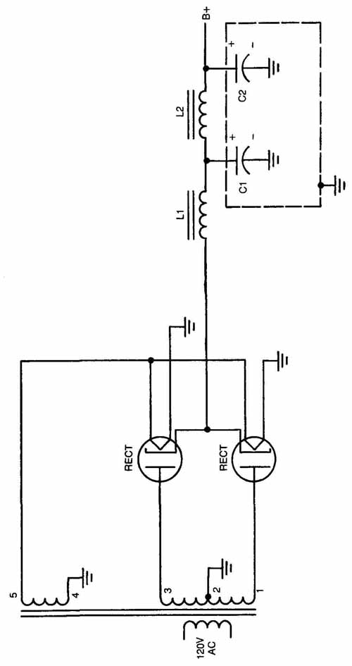
FIG. 5
• Filter Chokes. If any one of the filter chokes becomes shorted internally, the receiver will hum. Internal shorting seldom occurs; tests required to determine whether the coil is defective should be carried out only after other components have been checked. Iron-core chokes usually have an air gap in the core to prevent core saturation. The gap is kept open by a wedge of nonmagnetic material such as paper, copper or brass. If the gap material should drop out or if it were not there in the first place, the gap could close up from vibration of the core laminations. This would allow core saturation, which would produce hum.
• Power Transformer High-Voltage Winding. This power supply uses a full-wave rectifier, which means that the frequency of the rectifier output—the input of the filter—will be 120 hertz if the power line frequency is 60 hertz. If the winding numbered 1,2,3 should open between points 1 and 2 or between 2 and 3, an abnormal hum would result. Testing and replacing all chokes and filter capacitors will not correct the trouble, because the opening of one leg of the high-voltage winding changes the circuit to that of a half-wave rectifier. The output frequency is now 60 hertz, and the chokes and capacitors are not large enough to filter such a low-frequency hum. This condition could also be caused by a cathode-to-plate short in a full-wave rectifier tube.
• Tube Cathode-to-Heater Leakage. A 60-hertz hum can be caused by cathode-to-heater leakage in a tube, especially in the audio stages, which can readily pass low frequencies. As an example, the first audio frequency amplifier V601A in FIG. 1 would produce a 60-hertz hum if the cathode were to short to the heater. This tube is shown in FIG. 6. If the cathode and heater should touch, the heater and the cathode-bias resistor R604 would be in parallel as shown by the connection in the figure. This would put 6.3 volts AC across R604. The 60-hertz voltage would modulate the electron stream and cause hum. This could happen in an RF tube also, in which case the 60-hertz signal would modulate the RF when a signal is tuned in, and be demodulated by the detector. If a stage has no cathode-bias resistor and the cathode is grounded, the same defect would not be noticed because there is no place across which the 60-hertz voltage can develop.
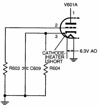
FIG. 6. Heater-to-cathode short.
Determining Frequency of Hum
When a hum is heard in the output of a receiver, the first step is to determine its frequency. In a set using a half-wave rectifier, there can be only one hum frequency: the line voltage. In this receiver in which the rectifier is a full-wave type, the rectifier output is 120 hertz when the input voltage frequency is 60 hertz.
If you do not have sufficient experience to be able to recognize the frequency, you can use the audio signal tracer shown in FIG. 2. Connect the tracer across a 6.3-volt AC source. One lead can be connected to the chassis and the other one to the ungrounded filament terminal of a 6.3-volt tube. A loud 60-hertz hum will be heard in the headset. If the hum in question sounds like the hum just heard, it is of the same frequency; if the frequency is higher, it is a 120-cycle hum.
If a 120-hertz hum is present, it means that the defect is probably in the power supply filter and that the filtering is in adequate. If a 60-hertz hum is present, the defect is not in the power supply; it is probably a cathode-to-heater short in a tube, or stray AC pickup by a tube grid. The one exception to this rule is covered in Power Transformer High-Voltage Winding.
Tracing Power Supply Hum or Audio Hum
• Sectionalization. Turn the gain control, such as R105 in FIG. 1, all the way counterclockwise, if the hum is still heard, it is coming from the power supply or the audio channel. If the hum is present in the audio channel and it is a 120-hertz hum, it is due to inadequate filtering in the power supply. If the hum is present with both gain controls turned on, and it is a 60-hertz hum, it could be from a cathode-to- heater short in a tube, or stray coupling to a grid, but it is more probably in the audio section.
• Isolation. If the hum has been traced to the audio section and is a 60-hertz hum, it will be necessary to find the stage where it originates. A quick and easy method of hum isolation is one that uses an audio signal tracer such as the one shown in FIG. 2. Connect one probe of the tracer to a convenient point on the chassis. Touch the other probe to pin 1 of AF output tube V603. If the hum is not heard, it is originating between this point and the detector. Touch the probe to pin 2 of V602A. If the hum is not heard, it is coming from somewhere between this point and the detector. Touch the probe to pin2 of V602A. If the hum is not heard, the hum is originating between this point and the previous test point, If the hum is heard, it is originating somewhere between this point and the detector. Move the probe successively to the input of the remaining stages toward the detector until the hum is not heard. This system eliminates the stages between the test point and the speaker whenever the hum is heard.
Tracing Modulation Hum
Modulation hum modulates, or varies, the RF carrier at the hum frequency. Because the carrier is RF, it can pass through the RF and IF sections; the detector will then demodulate the signal and the hum will be heard.
• Sectionalization. Turn the audio gain control to the maximum clockwise (on) position. If the hum is present with the control turned on but is not present when the control is off, the hum is originating between the control and the antenna. Pull out the last IF amplifier tube. This will stop the hum from getting through. Any hum originating in the RF section can get through only by modulating the RF carrier, and will have a frequency of 60 hertz. Therefore, the hum discussed below will have a frequency of 60 hertz.
• Stray Coupling Hum. One of the most important causes of hum is induction into the RF or IF section. Filter circuits or capacitors are usually at the AC power input to prevent this. If a capacitor in this circuit should open, hum would result. The simplest method of determining which of them is at fault is to bridge them, one at a time with a good capacitor.
TROUBLESHOOTING A NOISY RECEIVER
A receiver is noisy when the output, in addition to the desired signals, contains crackling, sputtering or frying sounds. Noises fall into two general categories—external and internal. External noise is from a source outside the receiver. Internal noise is from a source inside the receiver. Noise is made up of many frequencies ranging from audio to RF; therefore, it can pass through any stage even though it does not modulate the carrier.
Causes of External Noise
External noise is divided into two classes—atmospheric and man-made.
Atmospheric noise is caused by lightning and other natural electrical disturbances. Little can be done to reduce noise from atmospheric conditions. Usually it can be avoided by moving the receiver to another location, or by changing the operating frequency to one that is relatively free from interference.
Man-made noise can be produced from many sources, such as loose or arcing power lines, gasoline-engine ignition systems, electric motors and generators, other radio sets, diathermy machines, etc. Frequently, this type of noise is suppressible.
Loose or corroded connections in the antenna and ground systems are a frequent cause of external noise.
Causes of Internal Noise
• Transformers. Noise in transformers is frequently caused by corroded breaks in the windings. Primary windings in IF, RF and radio transformers are the worst offenders. The corrosion causes the winding to open, leaving a small gap across which the current may be conducted by the corrosion itself, or an arc may jump intermittently, producing sharp, rapid changes in current, and therefore noise. Transformer windings can work loose from their terminals, producing noise resulting from intermittent connections.
• Wire-wound Resistors. Wire-wound resistors are subject to the same noise troubles that occur in transformers. When a resistor winding works loose from a terminal, the result is a rapid rate of intermittent operation which causes noise.
• Potentiometers. Potentiometers are among the main sources of noise. The constant friction between the sliding arm and the resistance element causes wear and noise. As the resistance element becomes badly worn, the contact becomes very poor and, ultimately, intermittent. Noise results even when the control is not being adjusted.
• Band Switches. When the contacts on a band switch or a similar switching device become corroded and worn, a noise will be generated when it is set from one position to another. When the switch is dirty, it may be noisy. The contacts may become bent, causing an intermittent condition that produces noise.
• Tuning Capacitors. Though it seldom happens, tuning capacitors can become noisy, especially when the rotor plates are turned. Warping of the plates, shifting of the rotor shaft, and particles of metal slivers peeling from the plates are common sources of noise. Dust and dirt often carry fine metal particles, and if they become lodged in between plates, noise results as the rotor is turned.
• Tubes. Electron tubes generate noise that has several possible causes.
• Shot effect is produced because electron current consists of separated particles that leave the cathode in a random fashion, producing fluctuating currents uniformly distributed over all frequencies.
• Flicker effect is a low-frequency noise caused by small emitting areas of the cathode constantly changing their emission characteristics.
In tubes having more than one collector element, such as the screen and plate of a pentode, the random division of current produces uniform noise currents over the whole frequency spectrum of a tube output.
• Microphonics are low-frequency noises produced by motion of the elements of a tube. These are heard when the tube is subjected to vibration.
Other sources of noise in tubes are positive-ion-emission currents, positive-ion currents produced as the result of gas ionization and secondary-electron emission.
• Poorly Soldered Joints. Poorly soldered joints may be a very serious cause of noise. Such noise results from movements of the joint beneath a soldering job which looks good on the surface but is actually not well done.
• Mechanically Caused Noises. Tube shields that are not securely locked in place can move and cause scraping noises when the set is jarred. Loose screws and subchassis cover plates will produce the same scraping noises. The thing to remember is that noise is always caused by the rapid making and breaking of a circuit somewhere. Some common types of noise, and their probable causes, are listed in TBL. 1.
Isolating External Noise
Refer to FIG. 1. Turn gain control R105 to a point where the noise is heard. Disconnect the antenna from the antenna terminals. Short out the terminals with a jumper. If the noise stops or is reduced considerably, it is originating outside of the receiver. Remove the jumper and reconnect the antenna. Shake the antenna lead. If the noise gets worse, the transmission lead has a break in it or it is rubbing against a tree, pole, or other object. It is also possible that the antenna is rubbing against something, or a connection between the antenna and the lead-in is loose.
If the preceding tests indicate that the noise source is outside of the receiver, the noise is probably radiated noise picked up by the antenna. The trouble now is in the immediate vicinity and may be coming from a nearby power line, vehicle ignition system, motor, generator, or hospital equipment. If a portable or mobile receiver is available, take it to various areas that may be radiating noise. When a point is reached where the noise level increases in the test receiver, the noise source is nearby.
= = =
TBL. 1. Mechanically caused noises.
Type of Noise: When Noticed: Probable Causes:
Scratching
Scratching
Scraping
Intermittent crackling, scraping
When signal is being tuned in.
When adjusting gain control.
When changing bands.
When chassis is jarred.
Dirty tuning capacitors.
Worn gain control.
Worn wave-band switch.
Loose tube elements, screw or shield can.
= = =
Disconnect the ground wire. If the noise decreases, the ground connection is probably poor or the ground lead is too close to a noise source. If the noise increases, it is probably entering on the power line.
Localizing Internal Noise
Turn gain control R105 to a point where the noise is heard. Disconnect the antenna from the antenna terminals. Short out the terminals with a jumper. If the noise continues, it is originating in the receiver.
Turn gain control R105 to the extreme counterclockwise position. If the noise continues, it is originating between the gain control and the speaker. If the noise does not continue, it is originating between the antenna and the gain control. Use the method described later in Stage Blocking for locating this source of noise.
Isolating Noise
--Signal Tracing. In the audio stages, the audio signal tracer shown in FIG. 2 can be used to localize noise by the same method used to localize distortion and hum. Connect the ground terminal of the signal tracer to a convenient point on the chassis. Remove the AF output tube. Insert the signal tracer probe in pin 5 or 6 of the socket. If noise is heard, the power supply may be at fault. Check the power-supply tubes by substitution, and inspect all connections, particularly the connecting plugs and jacks. If noise is not heard, replace the AF output tube. Touch the signal tracer probe to pin 5 ol AF output tube V603. If the noise is not heard in the headset, the noise originates in the secondary of T601 or the speaker circuit. If the noise is heard, it originates in the primary of T601 or between pin 5 and the gain control. Move the probe to pin 1 of the same tube. If the noise is not heard, it is coming from the V603 stage. Keep touching the probe successively to the input or output of the various stages, working toward the gain control.
--Stage Blocking. The signal tracing method just described can be used with the signal tracer in the audio circuits only. If a signal tracer containing tuned circuits and a demodulator is available, it can be used in the RF and IF sections. A simpler and quicker method is stage blocking, which is similar to that used in troubleshooting hum defects. It can be used also in the audio section. Connect a clip to a test lead and fasten the clip to a convenient point on the chassis. Turn the gain control R105 so the noise can be heard with good volume. Touch the lead to the grid (pin 1) of V603. If the noise continues, it is in the V603 stage. If the noise stops, it is between pin 1 of V603 and the antenna. Touch the probe successively to the control grids of the various stages, working toward the antenna. If the noise continues when a point is shorted out, the noise is originating between that point and the last point that was shorted out. If the noise stops when a point is shorted out, the noise is originating between that point and the antenna.
TROUBLESHOOTING A RECEIVER THAT SQUEALS OR MOTORBOATS
Squealing and motorboating are terms sometimes used to de scribe unwanted sounds or noises in the output of receivers. Very low-frequency sounds are classified as motorboating because they sound like the “put-put” of a motorboat. Motorboating is usually the result of a component failure in the audio section of the receiver that produces regenerative feedback in the audio amplifiers. Squealing may be produced by anything that causes regenerative feedback in any of the amplifier stages of the receiver; however, it is sometimes produced by interfering radio signals. Disconnect the antenna and short-circuit the antenna terminals to determine whether the squeal is caused by external interfering signals or internal troubles. If the squealing stops with the antenna disconnected, the trouble is usually external.
Squealing Caused by Internal Conditions
The squealing sounds described in this section are high-pitched audio sounds. They are usually caused by unwanted oscillations in one or more stages of the RF or IF section of the receiver. Squealing may originate also in the audio section. In either case, the squealing is the result of unwanted oscillations. The difference is that the oscillations, if in the audio circuits, would occur at the same frequency as the squealing sounds. While in the RF or IF circuit the oscillations would occur at or near the frequency to which the circuits are tuned. The audible squealing sound is then produced by the heterodyning of two or more frequencies of unwanted oscillations with each other, or the unwanted oscillations with a received signal.
Causes of Unwanted Oscillations
The causes of unwanted oscillations are many but they have one thing in common. They each produce regeneration. Component failure in decoupling filters sometimes causes regeneration. If the capacitor becomes open or reduced in value or the resistor changes to a lower value, the filtering action is reduced and signal variations will occur in the voltage that was previously decoupled by the filter. These decoupling filters are used in DC voltage sources, such as AVC, AGC, plate, screen and bias supplies that are common to two or more stages of amplification. Poor shielding, a tube shield left off its tube after replacing the tube, or lead dress not being restored to its original condition after replacing a component, are all causes of undesirable coupling that may be regenerative and cause unwanted oscillations.
Sectionalizing Source of Oscillations
Audio Signal Tracing. Refer to FIG. 1. If the oscillating condition is present whether a signal is tuned in or not, and does not vary when the set is tuned, it probably is originating in the audio section. The audio section includes the detector through the audio output V603. Turn the gain control R105 to the extreme counterclockwise (off) position. If the squeal stops, it is originating between the gain control and the detector. If the squeal continues, it is originating between the gain control and the audio output terminals.
• RF Signal Tracing. If the squealing is present only after a signal is tuned in, and it is heard with all signals, the oscillation is most likely in the RF section. It would likely be between the first IF amplifier and the detector. If the squeal is heard only when the set is receiving a signal and it occurs mostly at one end of a tuning stage, the RF amplifier is probably at fault.
Localizing Squeal or Motorboating
The stage blocking method just described can be used. If the trouble is thought to be in the audio section, short out the detector. If the squeal stops, the trouble is between the antenna and the detector; if it continues, it is between the detector and the audio output. The shorting probe can be moved to any of the audio tube grid terminals. Whenever a point is found where the squeal stops, the squeal is originating ahead of that point. It is possible for the squeal to be caused by troubles in two stages. Therefore, if the trouble is corrected in one faulty stage, and it still squeals, another stage nearby may also be handled by removing tubes one at a time. Remove the AF amplifier V602A. If the squeal stops, the trouble is originating between this stage and the detector. If the squeal does not stop, it is originating between this stage and the output.
UNIVERSAL TROUBLESHOOTING CHART
The receiver troubleshooting chart in TBL. 2 will be of assistance in locating troubles quickly. The information is general and can be applied to any receiver. You can get an idea as to what the trouble is, regardless of the model.
= = = =
TBL. 2. Typical Capacitor, Resistor, and Inductor Failures in a Receiver Stage
Symptoms
|
DC Voltage Measurements |
Resistance Measurements |
Defective Part |
1. Feedback or burn, No Output or very weak signal 2. Decreased output and motor-boating. No output or very weak output. Hot screen resistor. 3. Weak Output Distorted Output 4. No output or weak Output Distorted Output 5. Severe hum or blocking No Output or very weak output. 6. No Output or very weak Output No output or very weak output 7. No Output or very weak output 8. No output or very weak output |
a. Normal b. Zero or very low from plate to ground. a. Normal b. Zero or very low from screen to ground a. Normal b. No reading across capacitor a Normal b. High reading from grid to ground. Positive polarity at grid a. No reading across component part b. No reading across component part a. no reading from plate to ground b. High reading from plate to ground High reading across resistor No reading from screen grid to ground |
a. Capacitor does not charge b. Partial or direct short from the B+ line to ground a. Capacitor does not charge b Partial or direct short from screen to ground a. Capacitor does not charge Partial or direct short from cathode to ground a. Capacitor does not charge b. Low reading across coupling capacitor a. Open circuit reading from grid to ground or to bias line b. Partial or direct short from grid to ground Or to bias line a. No reading from plate to B+ line b Partial or direct short from plate to B+ line Open circuit reading across terminals of resistor Open circuit reading from screen grid ‘o |
Plate bypass capacitor. a Open b. Shorted Screen bypass capacitor. a. Open b. Shorted a Open b. Shorted Coupling capacitor. A. Open b. Shorted Series grid resistor, coil or secondary winding. a. Open b. Shorted Series plate resistor coil, or primary winding a. Open b. Shorted coil Cathode resistor Open Screen-grid dropping resistor open |
= = = =