
Audio
Aids--On Phono arm geometry, turn-on/off noise, and zener size,
by readers Goodman, Shults and Grandfeldt.
PHONOGRAPH ARM GEOMETRY: A GRAPHICAL METHOD
THE TURNTABLE/ARM COMBINATION is the most ill-treated link in the usual playback system's chain of components. I hope this short article will prod you into some fresh thoughts on the subject.
I am concerned here with conventional pivoted arms of various lengths assumed to be rigidly mounted to a heavy motor board which also rigidly mounts a spinning platter. Three resilient supports suspend the heavy motor board for a soft ride in an environment not unlike an earthquake.
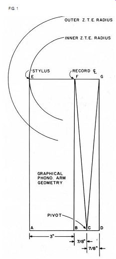
Most discussions of pivoted arms involve accurate measurement of angles in degrees and minutes. I shall mention no angles at all; instead, I shall define some specific dimensions and use them in an easily drawn rectangular chart (Fig. 1). Draw the chart full scale on 1/16" poster board or the equivalent.
A stylus travels across a record in a shallow arc. Should the arm attached to the stylus be of infinite length, this arc would approach a straight line.
Since we want to build a real arm, not a theoretical one, we must select something under 3 feet for this length.
The straight line is the ideal. Our arc should cross this line at two points of zero tracking error ZTE.
Outside these points, the tracking error is in one direction; between them it is in the opposite direction. The inner groove error is negligible. This is superior to the usual procedure of establishing only one ZTE circle at the innermost groove and letting the error increase all in one direction toward the outer groove.
A typical LP record has the inner groove at 2 3/ 8" radius, the outer groove at 5 5/8" radius. My two ZTE points are at 3" and 4 3 /4" radii.
The stylus of Fig. 1 is at point E in line with line AE. Point F is the record center. Therefore EF = AB = 3". FG equals the distance between our two ZTE radii, or 4 3/4" - 3" = 1 3 /4". Point C is our arm's pivot point. Since lines BC and CD are equal to each other and line BD and FG are also equal, then lines CF and CG must be equal forming an isosceles triangle FGC.
With the pivot at C, as stylus E traverses the record you will note that line EG will always cross the record center. True EG will deviate slightly in either direction as it traverses, but with a 16" or longer arm the deviation is small indeed.
Moving across Fig.1's record radii from E on the inner ZTE radius to the outer ZTE radius, point G assumes the center of turntable position perfectly for another ZTE position.
You may well ask, where is the arm on all of these lines? This decision is up to the builder. The arm may be straight, S-shaped, or any shape to connect pivot C to stylus E, with one qualification: the vertical movement of the arm must always swing on pivots on a line parallel to line AD.
This point was missed by four arm builders known to me-in other words it is an easily overlooked but important point. Do not goof here or your cartridge will roll on its AE axis with any vertical movement, thus destroying the Westrex 45/45 tracking.
Another natural question is, how long is line AE? An reasonable length the builder wises to select, with no need to change the rest of our chart at all. AE is a freely chosen variable.
When installing your completed arm, use a plastic drafting triangle lined up with axis AE and EG. mark point F on the triangle and locate the arm with this mark exactly over the center of the turntable. This may sound a bit tricky, but don't worry about it: it's a snap. While the triangle is thus located, traverse the arm and note how small the error is.
Line EG will stay almost over the center of the turntable spindle. Be careful with the stylus during assembly and alignment; perhaps you should place a guard or other protective device over it.
By using this simple graphical layout method, you will be able to build a low-tracking-error arm. I feel this is a basic improvement in a heretofore neglected area of the total audio system.
BOB GOODMAN; Livingston, TX 77351
SLOWING PLOPS
TURN-ON/TURN-OFF transients are a common problem encountered in both home-built and commercial audio equipment as one result of the almost universal acceptance of op amp circuitry. Although turn-on/off boxes will work as they are intended ( see Walt Jung's article, "The Speaker Saver"-TAA, 3/77, p. 4--or Robert Borden's Audio Aid, ''A Turn On/Turn-Off/Warmup Transient Eliminator--TAA, 1/78, p. 45), they will not help when an additional unit is turned on or off.
The following solution is both simple and effective. Each offending piece of equipment may benefit from these changes.
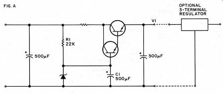
To eliminate turn-on transients in low level units, preamps, equalizers, etc., modify the power supply so it turns on slowly enough to be inaudible. Fig. A shows a slow turn-on supply: the time constant of R1 C1 controls V1 's rate of increase during turn-on.
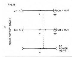
If you want better regulation, this circuit will turn on a three-terminal regulator just as slowly. Vary R,/C, to meet your needs: R, may be much larger and C, smaller. You can achieve quick turn-off by changing the power switch to a 3PDT as shown in Fig. B.
MARK. C. SHULTS; Madison, WI 53711
DIODE DIMENSIONS
FOR PEOPLE LOOKING to reduce noise, I suggest the use of higher rated diodes. This applies to signal, rectifiers, and zeners. I recommend subbing 1 amp for 1/4 amp, and 3 amp for 1 amp. For zeners, I use 1 watt for 1/4 watt, and 5 watt for 1 watt. You might consider this overkill, however, in some cases the improvement can be dramatic, not to mention the resulting increased stability.
[The Jung-White exploration of the PAT-5/WJ-1A (3/79) report similar findings. -Ed. ]
JOHN GRANFELDT Tualatin, OR 97062
---------------------
VERY FREE SUBSCRIPTIONS
Why pay out money for a subscription to this rather expensive journal when you can earn money writing for it instead? Offset the high cost of TAA by writing up those nice shortcuts, circuits, modifications, tips, techniques, and good ideas that your fellow readers would deeply appreciate hearing about. Just pen, type, or pencil your fresh ideas and send them along to our Audio Aids editor (Room AA) at Audio Amateur Magazine, P. O. Box 176, Peterborough, NH 03458.
We'll send you a nice signed acknowledgement card with profuse thanks on the day we receive it, then eventually we set to work editing, polishing and generally taking care of it.
When we publish it (at last) we'll send real, steadily inflating, U.S. money to you which may even offset the cost of subscribing. We'll eagerly be waiting for your response. Send in those ideas of yours. You'll be surprised at how pleased you'll be to see your name in print and the warm feeling that comes when you sham with others-and the even warmer feeling of having real money come to you through the mail. All right, typewriter covers off, pencil and pad at the ready, think, BEGIN.
------------------------
Also see:
A Family of Power Amplifier Power Supplies -- A versatile circuit for regulated DC in quantity, by James E. Boak
A High Accuracy Inverse RIAA Network -- New light and hardware for the phono curve's basic shape, by Stanley P. Lipshitz and Walt Jung
Test Report: Listening tests of the PAT-5/WJ-1A, by Laurence L. Greenhill, M.D.