DEPARTMENTS
- Intro
- AUDIO AIDS
- KIT REPORTS--The Heath AD-1308 Spectrum Analyzer
- JUST LOOKING
- LETTERS
Introduction to 3/1985:
Martin Colloms is a graduate engineer who writes extensively for the British audio press and is also widely known among loud speaker enthusiasts for his book High Performance Loudspeakers (Wiley, $29.95). In this issue, he surveys the state of our present knowledge of amplifier sound and calls for new techniques to measure the hitherto hidden factors that determine performance quality. J. Roberts shares his newest phono preamp --a stripped-down, high-performance 'Volkswagen' approach to the most challenging amplification task in audio's realm. A full kit for the project is available.
Dick Marsh offers his views on the reasons for using low feed back in power amplifiers.
And G. Galo has done a thorough, well-crafted upgrade of the classic and vintage AR turntable, guiding his fellow amateurs on a detailed tour of the project. Finally, A. Watling, in his dry, understated style, re minds us of the very real hazards of amateur craftsmanship (p. 39) with the added spice of his in imitable cartoons.
We have only one Audio Aid this time (below), but Paul Kelly's detailed instructions on circuit board fabrication are superb. Bill Sommerwerck winds up the issue (below) with an excellent report on Heath's AD-1308 half-octave audio analyzer, which receives much better than a passing grade.
Next time, Dick Marsh will be on hand with POOGE-3, Walt Jung and John Curl will offer a new measuring gadget for capacitors, and Erno Borbely will begin his two-part series on a new pre-amplifier design.
Just Looking
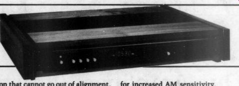
New from Crown International is the FM Three stereo tuner. It incorporates the Schotz noise-reduction (SNR) circuit, which pulls in more stereo FM stations and clarifies previously unlistenable channels. The tuner also features a “scan level ” control, which allows […] stops scanning locks onto a channel. Other features include six AM and six FM presets, signal Sp LEDs and a multipath indicator. The FM Three uses a digital detector section that cannot go out of alignment, drift with age or add distortion by mistuning. The unit also has a toroidal transformer to reduce hum and noise and an extra radio-frequency (RF) section for increased AM sensitivity.
For more information about the FM Three, write to Crown, 1718 W. Mishawaka Rd., Elkhart, IN 46517.
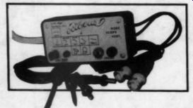
The Octopus electronics troubleshooter from Jensen Tools provides a fast, efficient method of troubling electronic assemblies to the component level, both in and out of a circuit. Used in conjunction with any dual-trace oscilloscope having X-Y function or with a single-trace scope that accepts external horizontal sweep output, the Octopus generates approx. +-3 peak-to-peak at 60Hz. When applied to the component under test, it will display the component's current/voltage response on the oscilloscope. By comparing a suspect component's trace to a good component's trace, the bad component can be quickly identified.
Also available from Jensen is the JTK-99 service technician's kit. It is designed for on-site or in-shop service and repair work. The kit contains all the tools necessary for servicing AM/FM, CB and ham radios; TV sets; hi-fi equipment; sound and communications systems; and electrical/electronic equipment of all types. Tools are conveniently positioned in four case styles.
For more information about either product or a free catalog of other test equipment and hard-to-find tools, write to Jensen Tools Inc., 7815 S. 46th Street, Phoenix, AZ 85040.
Labs has recently introduced a line of digital potentiometers called the DP-500 series Digipots. Digipots use side-by-side thumbwheel switches and are designed to generate a true potentiometer circuit with two input terminals and a wiper. They are ideal for voltage and current divider circuits.
Resistance values of from 10 to 50 M-OHM are available in numerous standard values as well as any specific value re quested. Standard tolerances of 0.05, 0.1 and 1 percent are available. Digipots come in 1 to 6 decades, and the power across the input terminals is 2W per decade minimum. Units are available for panel mounting or in a case.
Other features include updating instruments for truly digital control; no need for dials and multiturn pots; precise repeatability of setting; and an in-line digital front-panel readout.
To find out more about Digipots, con tact IET Labs, 534 Main Street, Westbury, NY 11590.
The David Hafler has introduced a car amplifier designed to meet the challenges of digital recording. De signed with the dynamic range and power requirements of the mobile com pact disk (CD) in mind, Hafler's car amplifier is rated at 100W/ channel with both channels driven into 4Q loads with less than 0.01 percent total harmonic distortion from 20Hz to 20kHz. It has a complementary symmetrical class A/B push-pull circuit and is direct coupled throughout with the exception of a DC blocking capacitor at the input.
The output devices are MOSFETs, while the power supply is a high-frequency MOSFET switching type, capable of delivering 40A of current to the amp drive circuitry.
The new Hafler car amp measures 10 by 8 by 2 inches and was specifically designed to fit into tight quarters, such as- the seat or mounted to the fire wall.
For details, contact 5910 Crescent Blvd., Pennsauken, NJ 01809.
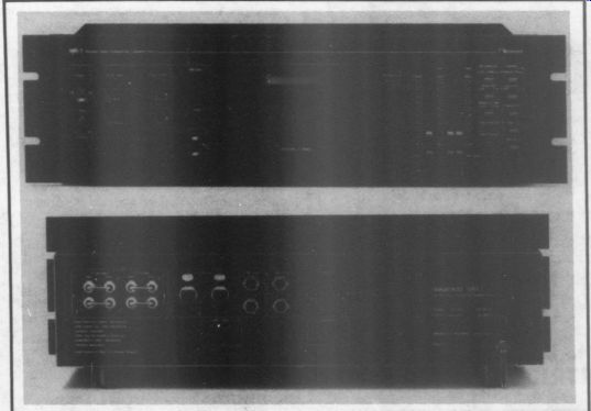
The Nakamichi MR-1 discrete three head professional cassette deck is the company's first entry into the professional recording and broadcast market.
Features include front-panel 0.25-inch line-input jacks in a balanced configuration to simplify temporary connection of signal sources with the MR-1. Balanced XLR input and output jacks on the rear provide permanent connection.
Standard 0.25-inch rear-panel jacks provide unbalanced connection to the MR-1.
The balanced inputs meet professional standards vis a vis input impedance (600 ohm) and rated input level (+4dBm) with 16dB of headroom to the maximum input level ( + 20dBm). Minimum input level is rated at -6dBm. The un-balanced inputs are designed to bridge virtually any source. A 100 k-ohm input impedance ensures negligible loading, and high-gain circuitry produces nominal recording level with an input of only -20dBV (0.1V). Nominal input level is 10dB higher (0.316V).
The balanced line outputs are de signed for termination in a standard 600 ohm load and have a source impedance for 10 0-ohm (balanced). Nominal output level is identical with nominal input level. The unbalanced line outputs have a 2,20 0-ohm source impedance and are de signed to work into a nominal load of 25k ohm. Nominal output level matches the unbalanced nominal input level (0.316V) with an output saturation point of 18dB higher (2.51V).
The MR-1 has self-contained Dolby B and C noise-reduction (NR) circuitry and provisions for use with external NR processors. The external NR loop is accessed via standard phono jacks that are jumpered when an external processor is not used. A subsonic filter prevents modulation caused by turntable rumble, record warp and other low-frequency resonances when recording from conventional phonograph records. The filter rolls off at 12dB/octave below 18Hz. A 19kHz multiplex filter provides more than 30dB rejection of the FM-stereo pilot.
More details are available from Nakamichi USA, 19701 South Vermont Ave., Torrance, CA 90502.
AUDIO AIDS
CIRCUIT BOARD ART FROM SCHEMATICS
I HAVE OFTEN ENCOUNTERED a schematic for a device that I wanted to terms. This 1 reversal is not The following method will allow you to generate a circuit board pattern and a stuffing guide from almost any schematic diagram with parts values. I have used this method successfully for a number of devices, including Dick Marsh's superlative pre-preamp from TAA 1/82 (p. 7).
Start by making an expanded hand drawing of the schematic, two if it is a stereo device. Add the parts values to the schematic and assign numbers to each component (R1,R2, C1, C2, and so on), using consecutive numbering from one channel to the other. Next, make a full size stuffing guide on graph paper with ten squares to the inch (proper spacing for IC pins), using the actual components to ensure proper spacing. Use a soft-lead pencil in making the stuffing guide and have an art gum eraser handy to save wear and tear on the paper.
As you locate each part on the stuffing guide, draw in a solder pad and the required connecting trace to the next component, then cross out that component on the expanded schematic. Using a red ball ERE, dies Nuts between the solder pads to represent the component and enter its assigned part number.
Do this for all the components, labeling pin 1 on all ICs and E,B,C on all transistors, as well as the polarity of all diodes and capacitors. As you draw each part on the stuffing guide, also list it and its value in the parts list (to be used during construction of the device).
After the stuffing guide is complete, draw a 3/16-inch ground plane around the circuit, allowing enough space for mounting holes at the corners. It is a good idea to add a ground line between channels on a stereo device. Until you have had a little practice with this procedure, you will find that you cannot run a trace to all the components. This means that you must use jumpers, but keep them to a minimum. When a jumper is required, simply draw in a solder pad, run a line across the trace in question with the red pen, draw another solder pad and label the red line 'jumper’ on the stuffing guide.
If you want to produce a real work of art, you can use stick-on donut pads, dual in-line symbols and drafting tape available from Mouser Electronics (2401 Highway 287 North, Mansfield, TX 76063).
Check the stuffing guide for accuracy and adequate spacing between traces and components. When working with components such as large capacitors and transistors with heatsinks, it is a good idea to leave these parts in place on the diagram until you have completed the circuitry in that area just to be sure you have left enough clearance between parts. A ¥¢-inch-wide circuit trace is sufficient for most applications, but I prefer to make the traces as heavy as the spacing requirements allow. This helps to reduce resistance within the circuit and also speeds etching of the board.
Now turn over the stuffing guide (drawing side down) and tape it to the light box described in the sidebar below.
When you turn on the light, you will be able to see the solder pads and circuit traces from the other side and in the proper 180-degree reversed orientation.
Using a fine-point black pen or felt marker, draw in the solder pads and circuit traces or use the stick-on donut pads and drafting tape.
You now have the three requisites for building the device-a numbered parts list (taken from the schematic diagram), a stuffing guide and the board pattern.
You will also be assured that the parts will ‘go together' properly with no spacing or location conflicts when you begin construction of the device.
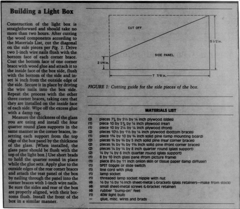
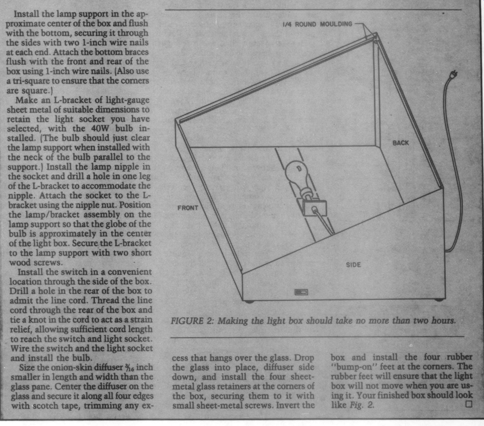
----------Fig.1-2
If you intend to build only one device, the simplest course is as follows. Make a photocopy of the artwork and trim it to size. Prepare the etched circuit blank and cover the foil side of the blank with a low-crepe masking tape. Cover the masking tape with double-faced po tape, available at most department stores. Strip the backing from the one tape and carefully apply the artwork to the blank.
Since you will not be able to adjust the position of the artwork after it comes in contact with the carpet tape, you should apply the artwork by first placing the blank in a vise, taped side up, with the top of the blank slightly above the jawas of the vise. Attach two short pieces of scotch tape to one end of the artwork and align the taped edge of the artwork with the edge of the blank at a right angle (forming an “L” with the artwork and blank). Attach the tape to the edge and underside of the blank with your free hand. Then, using a ruler or thin piece of metal, bring the artwork slowly into contact with the carpet tape while pulling gently on the free edge of the artwork to prevent wrinkling. Using the ruler ensures good contact between the artwork and the carpet tape. If you have any air bubbles that do not come in contact with the tape, simply prick the bubbles with a needle to evacuate the air, and the artwork will contact the tape.
Do not apply the double-faced tape directly to the blank, as the adhesive coating might separate from the back ing and adhere to the blank when you attempt to remove the tape later.
Using a fine-point punch, center punch all the component holes and the board mounting holes at the corners.
Cut out the mounting pads and circuit traces with a stencil or hobby knife and remove them from the blank, using the point of the knife and tweezers, as necessary. You must use adequate pressure to ensure that you cut through the artwork, double-faced tape and masking tape. The foil on the blank should now be exposed in the area of the traces and mounting pads. Carefully remove the artwork overlay and the double-faced tape from the blank. You will find that they come off quite easily. Spray the exposed areas of the blank with a colored spray lacquer (I prefer black) and slew §the board to dry for several hours. It is best to apply several light coats of lacquer, about 15 minutes apart, rather than one heavy coat. Inspect the blank between coats for adequate coverage and spray each coat from a different angle. After the lacquer has dried, strip off the tape mask, and the board is ready to etch.
Drill 1/16-inch holes in the blank at the mounting points and insert toothpicks in the mounting holes. Clip the toothpicks so that they hold the blank about 1/8 inch below the surface of the etching bath. If any corrections or trace repairs are necessary prior to etching, you can make them by applying finger nail polish and removing the excess with a stencil knife after the polish has dried.
When the etching is complete, remove the lacquer from the circuit traces with fingernail polish remover and cotton balls. It is a good idea to wear rubber gloves during this operation, as it can get rather messy. Do not drill the board until you have removed the lacquer. Other wise, the lacquer residue will clog the holes and require re-drilling. Tin-plate the board, and you are ready to begin construction.
Paul T. Kelly; Fort Wayne, IN 46815
Editor's Note: Although Mr. Kelly's “cut-tape ” method will work well, an alternate plan of making circuit board patterns will allow two additional means of making boards more easily.
Instead of taping and placing donuts directly on the reverse side of the ten square-per-inch graph paper, cover the reverse side with 3 to 5-mil clear acetate and construct the pattern with donuts, tape and IC patterns (buy 16-pin patterns and cut them for 14, 8 and 6-pin versions). Be sure to mark the comers of the board as well.
When the pattern is complete, buy sensitized board from your supplier. (In addition to the supplier Mr. Kelly mentions, Roy Trumbull, 833 Balra Drive, El Cerrito, CA 94530, is a good source.) You may use this pattern directly to expose the board, or with some systems, you can convert it to a negative version by a simple process.
After exposure, you may etch the board, clean it with a Scotchbrite pad and tin-plate it before assembly. You may also wish to send your mechanical pattern to a board maker. They charge minimum prices of 38¢ to 45¢ per square inch plus 1¢ or so per drilled hole.
Two such makers are International Enterprises ( 6452 Hazel Circle, Simi Valley, CA 93063) and Atlas Circuits ( PO Box 892, Lincolnton, NC 28092).
Turnaround is quick and cost is relatively low. (The Marsh boards would be $11.25 each plus 1¢ per hole.) Quantity discounts are available if you wish to make several boards.
Kit Reports
THE HEATH AD-1308 SPECTRUM ANALYZER
Reviewed by William Sommerwerck
Let's FACE IT: your average octave-band spectrum analyzer is a toy. Outside of enchanting you with a pretty display while the music plays, it is nearly use less. Hundreds of thousands of listeners have adjusted their octave-band equalizers for “flat' “' response with these things, yet the net system response is not flat. The limited resolution of octave-band analyzers cannot reveal the peaks and dips that their seductively flat rows of LEDs hide.
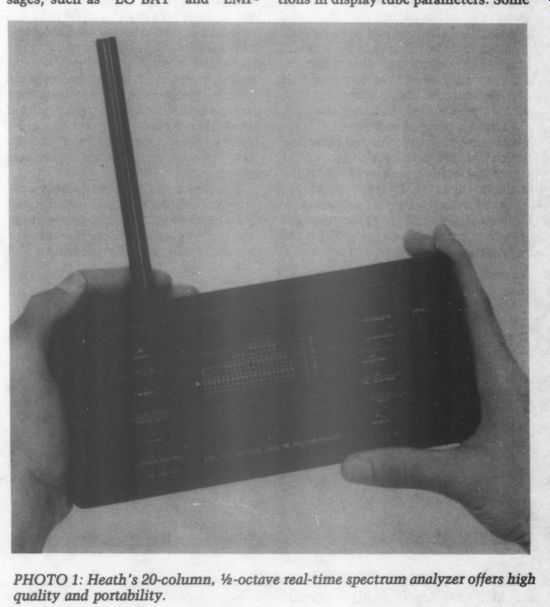
The Heath AD-1308 (Photo 1), de signed by Mark Rapaich, is an attempt to provide a much more useful instrument at a price ($280 plus shipping) that makes it virtually an impulse purchase for the serious (or even semi-serious) audiophile. Traditionally, Heath products have cost more than “comparable ” assembled equipment. Yet even counting assembly time at $10 an hour, this analyzer has more features and costs less than competing assembled units, including the Ivie 10A and the Canadian Audioanalyse. The former is pocket sized, but has no memory and is only octave band. It costs $650. The latter has several memories, but is still only octave band and costs $1,200.
Physically Speaking The 1308 appears bulky, but the cabinet edges are nicely tapered, and using Ni Cad cells puts the center of gravity at just the right point. (Alkaline cells weigh more and might make the 1308 uncomfortably bottom-heavy when you hold the unit for extended periods.) The case is made of ABS plastic, the same nearly indestructible stuff of which better telephones are made.
The switches are laid out so that you can comfortably reach them with your thumbs. Switches on the left include power (with an associated LED), memory (which stores or recalls a display, depending on where the switch directly below it is set), 1 or 3dB display resolution, % or 1 octave-band display, and display response (average, peak or hold).
The right side has the attenuator (which sets the reference level of the display in 10dB steps from 50 to 120dB), SPL (sound-pressure level) weighting (A, C or flat), SPL response (slow, fast or peak), input (mike or external), and memory (1, 2, 3 or difference).
The unit has a 12-by-25-dot vacuum fluorescent display, with each dot individually addressable. The designer took advantage of this to display messages, such as 'LO BAT’ and “EMPTY, ” to warn of a malfunction or incorrect operation. In cool weather (below about 65 degrees), the display is weak and flickers erratically until the unit has warmed up. In cold weather, warm-up can take five minutes or more. This is caused by an out-of-spec IC in early units. If your unit has this problem, con tact Heath's technical assistance department for a replacement chip.
Occasionally, one column's display appears as a fainter “ghost ” in another, unoccupied column. The designer says this effect is a function of slight variations in display tube parameters. Some
PHOTO 1: Heath's 20-column, 1/3-octave real-time spectrum analyzer offers high quality and portability.
PHOTO 2: The 1309 pink/white noise measurements with a real-time or swept-filter spectrum analyzer.
tubes show several ghosts, while others show none. The cost of drive circuitry to suppress it in every unit would have been prohibitive.
Circuit Description
You do not have to be an Intel stock holder to figure out that the 1308 is microprocessor controlled. The process or is an 8-bit device that includes custom ROM, but other than that, it is unidentified. It does just about every thing except the filtering, which is still handled by conventional analog circuits.
The designer says that sampled-data filters, such as those from Reticon, would cost about three times as much.
Each half-octave bandpass filter feeds a half-wave peak detector and capacitor, which charges to the peak value of the signal and holds it long enough for the analog-to-digital (A/D) converter to read it, as the detector outputs are scanned.
Unfortunately, the detector responds only to the positive signal peak; if the negative peak is higher, it goes unnoticed, two op amps are needed for full-wave rectification. Using two op amps would raise the price, however, and the board could not accommodate two devices anyway.
Although the 1308 also displays aver age signal levels for each band, it has no averaging detectors. Instead, the proc-
€ssor computes average values from the peak samples. Of course, this is incorrect, as the peak-to-average ratio for musical signals (the ‘crest factor') is not constant, being rather high for piano and trumpet and much lower for flute and organ. Is the 1308 capable of ac curate measurements? Surprisingly, the answer is yes.
First, any given half-octave contains far fewer frequencies than the composite signal. To obtain a high crest factor or create a signal where the positive peak level is much different from the negative, you must combine many frequency components. The act of decomposing the signal into bands reduces the crest factor for each band. The crest factor can never be lower than that of a simple sine wave (3dB), so lowering all the crest factors makes them more nearly equal.
Similarly, any differences in the negative and positive peaks will be reduced.
Second, we tend to use peak measurements for music (if we are not using the computed average values, we do not have to worry about their accuracy), and average measurements for frequency response, where the test signals (either sine waves or noise) have constant crest factors. What appears to be a 'design flaw' is, in practical terms, of no real importance.
A separate SPL display is provided.
The microphone's output is calibrated (via the choice of a gain-determining resistor) to give an accurate reading of the composite signal's loudness. The signal feeding the SPL display-but not the analyzer-may be displayed flat or with A or C weighting. Oddly, the curves are not shown in Heath's literature. Maybe the writer figured if you knew what they were for, you also knew what they looked like.
Unlike the half-octave bands, the SPL display uses a full-wave rectifier. It feeds a peak detector and two averaging filters with the response times specified by ANSI for fast and slow measurements.
Subjectively, the average display for the half-octave bands seems to respond at about the same rate as slow, with peak moving at the same rate as fast.
Two peripheral units are available from Heath to complement the 1308.
The 1309 white/pink noise generator (Photo 2) is digital. Feedback around a shift register generates a pseudorandom pattern of ones and zeroes. It is called pseudo because the pattern is the same every time you turn on the unit. The pattern is random enough, however, that the signal contains a smooth, broadly distributed range of frequencies. This noise is basically white. A separate “pinking ” filter supplies -3dB/octave correction for the pink-noise output.
The 1309 costs $50 plus shipping.
The 1308-1 rack-mount power supply (Photo 3) is in standard rack-mount for mat for easy insertion in an equipment rack. It has the power supplies needed to run the 1308 and recharge its batteries. There are jacks on the back for left and right line-level inputs, and a series of switches allows the display to show L, R, L+R and L-R.
The 1308-1 is not required for external powering or recharging. A 9-pin D connector on the back of the 1308 pro vides connections for these functions, as well as the line input and a preamplified mike output. The 1308-1 is convenient and not very expensive ($120 plus ship ping). It also has storage space for the 1309 and other junk, as well as a clip for the mike.
All three units are available at a special combined price of $400 when you buy them at the same time. In effect, if you buy the rack-mount unit, Heath throws in the generator as a bonus. This is a pretty good deal, so I recommend getting the package.
Using the 1308 You operate the 1308 much the same as any other analyzer. Functions such as setting the input level, choosing display response and resolution, and picking an SPL weighting curve are self-explanatory. But the designer has taken advantage of the microprocessor-based design to add several features not previously found in low-cost instruments.
Let's take a simple one. The response switch for the analyzer is marked aver age, peak and hold. The latter is not a true hold, but rather a peak accumulate, wherein the display shows the highest peak value for a band, until a larger one comes along. It also switches the SPL display to retain the maximum level.
This is not new: many other analyzers have this feature. What is new is the two-second delay after switching to hold. This prevents any noise produced when you move the switch from influencing the display, or it gives you enough time to move away from the analyzer so that your body will not af fect the readings.
The most useful new feature is the five memories-and the special difference mode they make possible. This feature lifts the 1308 out of the “toy ” category. It is possible to store the response curve of any signal source (usually the 1309 pink-noise generator) in the reference memory, then switch to difference mode, with the stored response automatically subtracted from the input signal. In effect, this allows you to use a less-than-accurate source to make an accurate measurement.
You can store the resulting difference display in a separate difference memory and recall it at any time for more leisurely examination. Three other memories allow you to store any regular screen display by setting the memory switch to 1, 2 or 3; setting the memory mode to store; and pressing the memory button.
(This provides the true “hold ” function; you need only press the button at the right moment.) You can recall any memory, including reference, by setting the mode to recall and pressing the memory button. All memories are retained with the power off. They are lost only if the batteries weaken or are removed.
Although the manual goes through the step-by-step procedure of using the difference mode, the process is not very logical, and it took me a while to figure it out. Briefly, here is what you must do:
Moving the memory switch to difference immediately places the analyzer in difference mode. No further action is needed.
Pressing memory while the unit is set at difference and recall causes the display to read REF. A second later, the reference response is displayed. Pressing the button again restores the main display. A third press shows DIFF, then a second later the difference memory. A fourth press restores the main display. In other words, the memory button toggles between the reference and difference displays when the unit is in difference/recall mode.
To store a difference or reference display, first press the memory button while you are in difference/recall mode to select the reference or difference mode, as shown on the display. Move the switch to store and press the memory button.
Measurements With sine waves at the specified center frequencies, the display response was + 1dB; 63, 180, 355 and 500Hz were up 1dB, with 2, 4, 8 and 11.5kHz down 1dB. Although some pattern is evident, the cause is not clear. Shifting the frequencies revealed that the errors were not due to any difference between the applied frequency and the filters' actual center frequencies.
With a single frequency at the center ...
--------------
Specs
AD-1308 Microphone self-noise level Flatness of direct input Filter center frequency accuracy External input impedance External input sensitivity, 90dB range External power source requirements Battery voltage Stand-by memory current Low battery indication Dimensions
*This is technically incorrect, at least for the analyzer. See comments in the section on measurements.
AD-1309 Frequency response (white noise) (pink noise) Output level RMS (both) Output level peak (both) Power requirement Dimensions Weight (with battery) Price ADA-1308-1 Frequency response Signal-to-noise ratio L-R common-mode rejection* Input impedance Charger output current Supply output voltage Supply output current Overall dimensions 33-126dB SPL*
+ 1dB, A weighted
<36dB SPL, A weighted (pink noise) ANSI §1.4-1971 (1976 rev) ANSI §1.4-1971 (1976 rev)
+ 2dB on analyzer display (pink noise, anechoic environment)
+1dB
+8%
> 10k
0dB (350mV RMS, = 10%) 10.5V max, +10%, @ 425mA 10V max, 6V min, @ 425mA 150pA max 6V, 5% 9.25 by 4.5 by 4 inches 23.5by 11.4 by 10.2 cm 2.5 pounds (1.3kg)
$280 plus shipping
+ 3dB from 20Hz to 20kHz
+ 1dB from 20Hz to 20kHz
>350mV
>1.5V 9V battery (NEDA 1604) @ 18mA max 2%s¢ by 4% by 4Y inches 6.5 by 10.5 by 10.3 cm 11 oz. (300g)
$50 plus shipping
+ 2dB, 10Hz to 50kHz 50dB, referred to 200mV 40dB, 20Hz to 10kHz 22k 100mA, * 10% max 9.75 to 10.5V DC 750mA max 19 by 5.25 by 8.5 inches 48.3 by 13.7 by 21.6 cm 5.25 pounds (2.4kg)
$120 plus shipping
This spec is overly optimistic!
With the 1% resistors supplied, the worst case gain variation between the inverting and noninverting inputs of the L -R op amp would be 4%, giving a CMRR 12dB worse, or 28dB. Of course, you can easily hand-select the resistors. See the section on Assembly Hints in the article.
All three units are available at a special combined price of $400 when pur chased at the same time. Assembled units are NOT available.
---------------------
... of one band, the output in the adjacent band was down a healthy 12dB. The de signer has clearly opted for a relatively high Q, at the expense of flatness. This is shown by another measurement: the output of the 1kHz band was down 6dB at 820 and 1,150Hz, which is just about equal to the rated half-octave band width. When you are down 6dB at band edge, you cannot be very flat within the band. This seems to be a reasonable trade-off, as the filters are simple bi quads (two-pole) and so are limited to a 6dB/octave roll-off. In such a case, reduced interaction between bands is probably more desirable than flatness When I fed the 1309's pink noise to the analyzer without compensation, the response was not particularly flat, with a variation of about + 1, - 2dB. The ex act error is difficult to determine, as the display is not stable, even in average mode. This is mostly due to fluctuations in the generator's low-frequency output.
Because the display resolution is limited to 1dB, slight changes in input level will make the apparent response error larger or smaller, as these variations interact with the display's 1dB quantization.
With the difference mode engaged, the pink noise met its spec of + 1dB. The 'true’ response was even better than this because all the variation was due to generator fluctuations below 250Hz.
These fluctuations might cause problems when you are using the difference mode with the pink-noise generator. It is important to store the reference display when the response is relatively flat.
You can test your choice by looking at the noise source in difference mode.
When the fluctuations are (mentally) averaged out, the response should be flat. I mislaid my calibrated micro phones, so I could not verify the flatness.
With the analyzer's mike poked at my Acoustats, the overall response was pretty consistent with the way I think the speaker ought to measure, but there seemed to be a 4dB bump in response at the 5.6 and 8kHz bands, whether the source was noise or music.
If this apparent error was real, it must have been caused by a post-production defect. Supposedly, each mike capsule is calibrated, with the corrections incorporated in a PROM supplied with the capsule. The processor checks the PROM each time you turn on the 1308.
If the PROM is installed, the processor reads the corrections and stores them elsewhere. If the PROM is removed, no corrections are applied, allowing you to connect another microphone to the mike socket. The unit warns you of the PROM’s removal or failure with a “MIC ERR ” display.
No specification is given for battery life. I purchased six GE NiCad C cells and found that a full charge will run the 1308 continuously for at least 3.5 hours.
Used intermittently, this should be enough for one or two days' work.
Alkaline cells should power the 1308 about ten times as long. Battery ex change is inconvenient, as you must remove several screws and carefully separate the case halves. If you plan to purchase the rack-mount power supply, disposable cells are not a good buy.
The common-mode rejection ratio (CMRR) for the L-R input on the 1308-1 was better than 55dB at 2.8kHz and below, and better than 43dB below 20kHz. This beats the spec handily. I hand-selected the resistors in the L-R circuit (see the Assembly Hints section below), but most of you should be able to do the same.
Those who already own the 1308 might have noticed that individual bands sometimes show levels equal to or greater than the overall SPL. This is, of course, impossible. Is the 1308 out of adjustment? Well, it has to be. A pink noise input has equal energy per half octave. That means the overall level, as shown on the SPL display, will be at least 20 times as great (13dB), as 20 half octave bands are displayed. A third octave analyzer with, say, 32 bands would show a discrepancy of 15dB.
If the analyzer were calibrated so that the frequency display showed “absolute ” SPLs for each band, it would “sit ” about 13dB below the SPL display. This would not be too bad for a 3dB/division scale, as the 1308 then displays a 33dB range. But for 1dB/division, it can pre sent only an 11dB range. Most of the spectrum would then be off screen.
Therefore, as with most analyzers of this type, the spectrum display has been moved up about 13dB so that you can read it and the SPL at the same time without having to change the attenuator setting. Just remember, the spectrum readings are relative, not absolute.
Assembly Hints The 1308 is not especially complex, but because it has hundreds of parts, I would not recommend it to an inexperienced kit builder. (Electrical engineers who have never assembled a kit before are excluded from this group, of course.) The following tips might save you some aggravation.
The set screws with hex slots seem to be made of a softer metal than the Allen wrench supplied. Go gently, lest the wrench slip and enlarge the slot to the point where you cannot turn the screw.
This applies particularly to the plastic socket at the base of the microphone wand. “Tap ” the socket first, then insert it in the tube and replace the screw.
Or just forget the screw, and super-glue the socket in place.
The instructions on page 32 of the manual do not emphasize that it does matter which way J201-J207 are inserted. These jacks are not longitudinally symmetrical, so if you insert them the wrong way, the boards will not mate.
The number “1” on top of each jack should align with the corresponding digit on the circuit board.
The various pin-like plugs carry an in visible layer of varnish. As a result, my unit did not work at first. You can clean the plugs with alcohol or by repeatedly mating them with the sockets-prefer ably before assembly.
The front panel label does not line up very well with the holes on the case, so take time to decide how you want to align it. Press it in place carefully: once stuck, it cannot be moved.
In the 1308-1 rack-mount power sup ply, R125, R126, R129 and R131 determine the common-mode (L +R) rejection of the difference (L -R) mode. It has ten 50k resistors. Measure them with a digital ohmmeter and pick four with the same value. If you cannot find four of identical value, choose them so that the ratio of R131/R125 is as nearly equal as possible to R126/R129.
Although this might be obvious, leave all the 1308-1's hardware loose until the unit is fully assembled, then tighten everything. Otherwise, you might find yourself loosening one thing to make room for something else.
Analyzer Applications
Now that your analyzer system is assembled (about 30 to 40 hours' work for all three units), what can you do with it? Letting it sit in your equipment rack and do no more than display the spec tral content of your program material is less than ideal. After all, you can buy color organs for a lot less money.
Using the analyzer to set up your octave-band equalizer is of questionable value, not because of any deficiencies in the 1308/ 1309, but rather because octave-band equalizers are not really suited for detailed room equalization. By the way, the manual's suggestion that the 1308 be switched to octave-band analysis for such use is misguided. The analyzer should have better frequency resolution than the equalizer so that you can better see the character of the corrections being applied.
A better use is in setting tape-recorder bias. The analyzer has enough frequency resolution to give you a fair idea of the machine's “real ” response. The 1dB resolution is a limitation. You might have to “wiggle” the bias to obtain +1 and - 1dB responses, then pick an intermediate position. On the other hand, the use of pink noise is more accurate than single frequencies, as it includes the effects of high-frequency self-bias.
Another application might be helping you find ey speaker location that produces the smoothest, most extended bass response. The difference mode is especially useful for comparing the response at various locations with that at the present position. Are you aware of the ( Roy) “Allison principle ”? By symmetry, the room's effect on bass response is the same even if the positions of the speaker and the listener are reversed. Therefore, to find the best speaker location, place the speaker in the listening chair and move around the room with the analyzer.
You could use the peak accumulate mode to compare two recordings (for in stance, an LP and a CD or a disk and a cassette) for peak output in each band.
You could place one measurement in the reference memory so that the other would read out directly as the difference.
Do not overlook the 1308's excellent sound-level meter, with average, peak and peak accumulate modes, as well as true A and C weighting. A comparable assembled meter would cost around $150. I have found it useful for measuring loudspeaker sensitivity and peak output level In short, the 1308 satisfies the need for an analyzer that is more than a toy, but that sells for a toy price. It is a genuinely useful product, so if you have even the least interest in owning an analyzer, by all means get this one.
Of course, a third-octave analyzer would be even more useful, but they are all too expensive. Mark Rapaich, the designer of the 1308, has also designed a third-octave analyzer that includes features such as third-order, phase compensated filters. Heath decided to manuf. the 1308 instead because the company wanted to keep the kit price under $250. (I guess Heath settled for $280 because the 1308 turned out so well.) Once you have bought your 1308, write to Heath ( Benton Harbor, MI 49022) and tell them you want and need a third-octave analyzer and you know they are sitting on a wonderful design that would make oodles of money. It couldn't hurt!
Manufacturer's comments:
Thank you for the opportunity to comment on Mr. Sommerwerck's review of the AD-1308 system. While I agree in general with his description of the technical details of the unit, I would like to clarify a few items.
The main reason for choosing a peak detector circuit in the filters was to eliminate the need for 20 adjustments and to provide a “real” peak-reading capability.
Most real-time analyzers are average responding, a display that works well with sine waves and to some extent noise, but that hides a wealth of information when used with music and some noise. We chose a half-wave peak detector because of the space requirements of an accurate full-wave circuit, with the added cost being a very minor factor. I would also like to point out that all the competitive real-time analyzers I tested during the development of the AD-1308 used half-wave circuits.
The variations in the response of the pink-noise generator at low frequencies are due to the fact that these measurements require very long integration times, which make the display slow to respond on music or other signals. We made this choice to provide a faster up 20 00 the SSA with the result that low-frequency levels bounce on noise. Using the difference mode will help minimize this problem visually.
The noise generator does meet its frequency response spec of + 1dB and is a very accurate source of white and pink noise when measured by ANSI standards.
Using compression techniques and parallel generators to minimize the peak-to average levels results in a noise generator that does not meet international standards for random noise.
After talking with Mr. Sommerwerck, I think that his suspicion of a defective is correct. A few microphones were damaged by rough handling during the pre-production test run. I thought that we had found and removed all of these, but apparently not. If you have an early AD-1308 and the bag in which the microphone was packed does not have a small hole punched in it, your microphone might have been damaged.
Contact the technical correspondence department at Heath if you are in doubt.
Mr. Sommerwerck's explanation of a level shift between the 1/3-octave display and the SPL display is not correct. The reference level for both displays is the same. If the SPL display is used in the peak mode with a wide-spectrum sound source, the display will indicate 10 to 15dB above the energy level in any 1/3-octave band, as it should under those measurement conditions. The spectrum display levels are not relative as he states.
His comments about the 1/3-octave analyzer are not really correct either. We do have a preliminary design of the filter set for a 1/3-octave analyzer, but such a product is a long way from a workable design. The cost and size of such a unit would be much more than the obvious few extra filters that seem to be required.
I doubt that few hobbyists could afford such a product, as much as they might like one.
In many years of using several competitive real-time analyzers, I was frustrated by many of their design limitations. When I was able to incorporate solutions to some of those limitations in my design, I was pleased to see that Mr. Sommerwerck tended to agree with my ideas.
MARK RAPAICH; Design Engineer, Heath Company
Letters
CORRECTION: LOW-Z REGULATOR
I HAVE ONE correction and a simplification pertaining to my article in TAA 2/84, ‘A High-Voltage, Low-Z Regulator' (p. 25).
I apologize for taking so long to supply the correction, but if it was not for an unfortunate reader who built the circuit as shown, I would still be unaware of my mistake.
The problem is with the pin-outs for IC1a (Fig. 5, p. 28). They are correct as shown for the NE5532 (industry standard, eight-pin package for dual compensated op amps), which is not recommended for this application. In stead, either the NE5534 (single op amp, eight-pin package) or its dual version, the NE5533 (14-pin package), should be used. Both are uncompensated, and the resulting extra open-loop gain can reduce regulator output impedance.
Table 1 shows the proper pin-outs for each regulator type when used as IC1a.
TABLE 1
PROPER PIN NUMBERS
Pin NE5532 Function (Do not use) NE5533 NE5534 (+) power 8 7 (=) power a 4 4 (+) input 5 6 3 (=) input 6 7 2 output 7 10 6
The simplification consists of replacing the current limiter (Q1-Q6, R1-R9, L1-L3, D9 and Z1 in Fig. 4, p. 27) with an approximately 2000, 10W resistor in series with a 0.125A fuse. The resulting regulator will still have short-circuit protection, but unlike the solid-state current limiter version, the regulator will not bounce back upon removal of a short. (I have not yet figured out how to extend short-circuit protection to the fuse.) The basic regulator appears in Fig. 5 on page 28. Break the connection be tween the unregulated B+ supply and the Q1 collector/D6 cathode, and insert the series resistor/fuse combination.
The B + unregulated supply can be as high as 350V. For higher B + ratings, you may use a zener for D6 (refer to the text).
I suggest using a zener value of about 250V. You can generate the op + /op ground/op - supply by using an other wise uncommitted (floating) trans former winding capable of generating voltages in the range of 6 to 24V RMS, along with a couple of power diodes and capacitors. An example of such a circuit using the 6V winding is shown in Fig. 4 on page 27. Good luck!
Christopher PAUL
Bayport, NY 11705
CORRECTION: NOISE GENERATOR
I HAVE just BECOME aware of a few minor errors in my article 'A Digital Noise Generator' (TAA 1/85, p. 17). In the schematic diagram on page 19, the polarity of diodes D3 and D4 is reversed, but the polarity in the stuffing guide on page 20 is correct. Also, for optimal operation, the value of R21 should be 47k, and the value of R12 should be 4.3k. These values are not critical, however, and readers who have already constructed the unit should not experience any problems from this source.
Ben POEHLAND; Malvern, PA 19355
CORRECTION: CURCIO PREAMP
J.J. Curcio Has informed us that IC1 in his tube preamp article (TAA 2/85, p. 7) should be a Motorola MOC3040 device instead of the 4030 unit listed in the Parts List (p. 9) and the schematic (Fig. 3, p. 10). We apologize for any inconvenience this might have caused. -Ed.
PREAMP UPDATE:
HAFLER DH-110
In TAA 2/85, Bill Cruce, teamed with Jim Boak and Pat Amer, characterized the sound of ten preamplifiers as they heard them perform through their sound systems. Early in the review (p. 20), they referred to the Hafler DH-110, explaining that although they did not listen to this preamp in the current round of listing tests, they basically agreed with Mr. Amer's earlier (negative) assessment of the unit (TAA 3/83, p. 44).
Upon rereading the issue, I got the un comfortable feeling that by repeating on ly this negative comment, we were not doing justice to the DH-110, which is the best-selling preamp kit in the world today. To add insult to injury, we repeated the negative view in the photo caption on the same page.
In fairness to the Hafler unit, we would like to point out a more positive account of the DH-110's capabilities in Steve Birchall's review (TAA 1/83, p. 51.)
-Ed.
MERRILL MODS MAKE A DIFFERENCE
I HAVE NOT READ any comments Or reviews of the Merrill modifications for AR turntables, so I thought I would share my experiences with your readers.
When the motor in my 15-year-old AR XA turntable finally developed noisy and loose bearings, I began to look around for a replacement. It was a tossup between getting an original replacement from AR and sending to Underground Sound ( 2125 Central Ave., Memphis, TN 38104) for the Merrill mod. I finally opted for Merrill because of the address and price availability. I was also curious about what the extra torque motor would do in terms of start-up time. The original motor takes one to two full platter revolutions before it gets up to speed.
of my written request, and it was accompanied by four pages of writ ten instructions to prevent installation problems. I only had to drill two holes, and total down time was less than 30 What 1 was not prepared for was the startling sonic improvement. The bass extension, which I have always felt was somewhat lacking in this turntable, went down at least another half octave.
Total bass solidity and tautness improved dramatically. Many records now have an almost frightening impact, as I still expect to hear a vague and anemic bottom end. The improvement extends well up into the midrange, producing a more forward and less smeared sound. I am not sure that I have ever improved my entire system so much for such a small investment. A somewhat laid back system has become very “up front' “' in sound, and my listening experience has been rejuvenated.
I should add that other modifications to my AR turntable have included the addition of an Oracle mat, a modified Rabco SL8-E tonearm with a Dynavector 17D cartridge, and a slightly re tuned suspension to accommodate the mat and heavier arm. An old Radio Shack record clamp also adds to the sound purity.
I would encourage anyone considering this particular Merrill modification to proceed. I have no connection whatsoever with the company, but feel that their diminutive ads understate the capabilities of their modifications.
ANDY CATANZARO; Wauwatosa, WI 53222
Editorial Objections
[…] I object to Critic editorial in TAA 1/85. I agree with much of Mr. Dell's argument, and I de fend his right to say it. But as a longtime subscriber to TAA (since Issue 1, Winter 1970) and other audio publications, as a digital and audio designer, as a writer and as the publisher of a similar “under ground ” computer magazine, I find Mr. Dell's tone unbecoming, offensive, patronizing and self-righteous-especially in light of TAA's own biases and failings.
Can TAA criticize other publications for weaknesses where TAAA itself fails miserably? I have not based a single purchase on TAA's comments-because it reserves comment until products are long gone and later tells us how to “fix ” from Old Colony, must worry little about losing advertisers, since for evidence he swallows whole the comments of his British cronies. Although he holds up British magazines as ex Sa, I reject British product reviews points of view as unsuitable to American tastes. The British and Americans do not to pick the same nits, and I will take pseudo-objective American test reports over British opinion any day.
I am weary of Mr. Dell's British bias, reflected in TAA's failed crusade for the snobbish 10nF and 4k7, and of its British affectations in neither redrawing schematics nor editing articles for an American audience. The results-all intellectual pretense and stuffy writing- have never in TAA's 15-year history produced an article as insightful, considered and well-written as Edward Tatnall Canby's regular monthly column in Audio.
Tangential, you say? Isn't the issue how major American publications re view audio products? That part I can ad dress simply. Sure, the American majors review poorly, sometimes slyly and under the guise of 'test reports’ rather than reviews. But at least they do it! Where are TAA's reviews each month? Where was TAA when compact disks (CDs) arrived and grew up? (I learned about the one-DAC delay problem in CDs from the major American audio publications. How come Mr. Dell area reading it?) Of course, it is easier to tell someone how to fix something after they have already done 99 percent of the difficult design work for you. Consider that neither TAA nor its British cousins has pioneered in describing, reviewing or presenting new technology, but rather prattled on relentlessly about theory, sniped at new products and only be grudgingly accepted new developments.
The issue, then, is far more wide ranging than merely reviews, and that is my complaint with Mr. Dell's editorial.
For example, I am still waiting to read about PCM (pulse-code modulation), delta-mod and FM recording on videotape in TAA. I have been using Sony's Beta hi-fi system with great pleasure, recording live concerts and then editing the results onto dbx reels.
Will Mr. Dell eventually tell me how to make Beta hi-fi “right ”? And how about dbx, which is not exactly current news? I would be interested in learning more about tracking problems, head bump and frequency response. I can measure the slight differences that are magnified by dbx. Will TAA ever tell us how to deal with TEAC's miserable tape heads, the weakest part of those workhorses? When will TAA discover that the Burr Brown OPA-111 op amp has been around for more than a year and looks far better than those comfortable old NE531, LF351 or AD544 devices? How about some of that instead of another power amplifier revamp, noise generator, Dynaco rework, signal generator, “classic ” circuit or multipart article on Ambisonics where all the t has been discontinued by the time it is published? Every project in TAA 1/85 already been done by the majors, except for the 11usec delay unit, although the delay problem itself has been reported.
Do you see my point? I am pleased to receive TAA each month, but TAA and Mr. Dell's biases are just as unhappy as that of the major publications. Closeted with a small circle of friends, develop ing cultivated prejudices, he seems, alas, as haughtily rigid as the major audio publications are slyly defensive. I just hope he will wait another ten years before he tries to bite the big boys' ankles again.
So please keep it down, Mr. Dell. TAA is great-in its place. But as a lifelong audio amateur who also subscribes to Stereo Review, High Fidelity and Audio, I can say that I am satisfied with their reviews, as I have learned their biases and blind spots. You point out their blindness while ignoring your own neglect. The audio industry that you say needs “revitalization ” has done pretty well (new tape formulas, integrated circuit technology, direct-to-disk, laser disks, PCM and delta-mod, Beta/VHS stereo hi-fi, digital synthesis, and so on) in the 15 years that TAA has been tinkering with the same old projects.
Maybe it is TAA, left a bit behind in the technological whirlwind, that needs some revitalization.
Dennis B. Kitsz
Roxbury, VT 05669
Mr. Dell replies:
Mr. Kitsz faults us for not doing what we never intended to do. TAA has never promised to do general consumer product reviews. We review kits and attempt to characterize their sound quality. Mr. Kitsz then raises the well-worn objection, “Unless the critic does the task better, what right has he to criticize! ” This logic removes not only Mr. Kitsz's grounds for criticism of TAA, but also any basis for almost all criticism.
Our bias is not pro-British; it is pro-clarity. British technical language is generally, more apt. Nanofarads and the notation “2k2” style of those who are not just British: the majority of European establishment uses these practical aids toward clear expression. Mr. Kitsz's summary of British reviewing style a whether his judgments are fair or represent even cursory knowledge of their content.
I will accept Mr. Kitsz's assertion that he is a longtime subscriber to TAA and many other publications. If I take his letter as evidence of whether he reads them or not, the evidence is not very convincing. He could have read about PCM in a two-part article back in 1975, Issues 3 and 4. And he refers to TAA twice as a monthly.
More seriously, Mr. Kitsz apparently sees US audio review shortcomings as merely “sly ” behavior, which the knowledgeable can decipher. That sly behavior is about as moral as a carnival shell game. US audio reviewing in the three majors too often fails to give any real basis for consumer choices or for a genuine discussion of equipment quality. Apparently in Mr. Kitsz's world, British reports of equipment faults are irrelevant snobbery, while consistent silence in the US audio press about such faults is only a quaint, pros habit.
From an ethical viewpoint, the best one could say about these evaluations is that they are a brand of moral nihilism, an easy-going, open-minded tolerance of any form of behavior-except British, of course.
JUNK FOOD FOR THE MASSES
I AM ONE OF THOSE who wants to see a bad review of audio equipment when it is warranted. I subscribe to Stereo Review only for the Rodrigues cartoons and because our local junior high school has an annual magazine subscription fund raiser. Most of Julian Hirsch's reviews are essentially worthless and have a ridiculous format for presenting useful information (no graphs, no waveform photos, trite “it sounds better than many units costing two to three times as much ” statements).
Even more suspicious is the form the record and CD reviews have taken. I grant that a performance assessment is a matter of personal opinion and taste, but these reviews show no apparent ob a . :
objectivity and certainly very little criticism of the sound or recording technique.
of Stereo Review has 17 classical recording reviews (not counting “Best of the Month ” and other special reviews), with the following assessments of record very, very good, excellent (three times), fine (three times), variable, good (twice), big scale, top drawer, splendid and vivid.
Now, I know that if I went out and bought' 17 records, I would be lucky to find one or two excellent or even very good sounding ones. Talk about feeding junk food to the masses!
V.H. Estricx; Fullerton, CA 92635
A REASONABLE REVIEWING POLICY
Before BEING OVERLY critical of the American press, let's first consider the models your editorial in TAA 1/85 presented for comparison-the British and computer publications.
The British, although critical of some products, largely restrict their highest praise, particularly in high-end items, to British products. Although it is entertaining to read the critical reports, I doubt that it is much more difficult for the British press to find Japanese and American products to jab at than it is for Stereo Review to find items to praise.
As for the computer magazines, their relatively narrow market forces review of a higher percentage of available products, and the faults are pretty obvious.
Computer users as a group know a lot more about their products than do stereo users and would come down much heavier on a computer publication that conned, either through commission or On the other hand, most stereo users just want to listen to music and are satisfied with any system that works reliably. The commercial press serves those people reasonably well-choosing to review only relatively reliable, decent-sounding equipment. And the commercial US press certainly seems more catholic in its praise than does the British press.
Where the US press fails seems to be in the area of damnation-no slams, witty, righteous or otherwise. The reason for this seems to be twofold. The first is fear of losing advertising revenues, which is probably mythical.
Where else would Brand X Audio advertise--Good Housekeeping! The second reason is fear of a lawsuit in this ever litigious nation. Consider the abominable expenses Consumer Reports incurred for printing its opinion of the Bose 901, an opinion with which most people of intact hearing would concur after mini this suit by all publications should have been a boycott of all Bose advertising and equipment reviews, until Bose came to understand that it does not have the power to control what the press can and cannot say.) What would be a reasonable reviewing policy? Priorities would include the following:
Good buys for the dollar and exemplary products.
Highly hyped products that are or worse.
“State-of-the-art ” products.
Brief commentaries, a la Hi-Fi Stereo Buyer's Guide ( “Adequate for play room use... ”'), on products not worthy of full review due to sonic or reliability problems. (How Julian Hirsch, et could have saved me cassette deck pains with such reviews!)
Answers to reader inquiries, as in Hi Fi Answers.
Why not let editors state their bam t in specific systems? Again, the reader would come to know the magazine better.
And what would be the results of such a policy?
Increased circulation for the first commercial magazine to make the change. Loss of a few advertisers would be balanced by higher rates for the wider audience. Advertising demographics might also improve.
Pressure on manufacturers to produce better goods and increased sales of praised items (witness Stereophile's effect on the FMI-80).
Pressure on the underground press to engage in editing, a skill handled well in the commercial magazines (ETC and Heyser in Audio notwithstanding), but plagued with inconsistency and pretention in the undergrounds.
A better-educated audio public. As readers see a divergence of opinion rather than the pablum stuck to today's glossy pages, they might come to listen for themselves.
A precedent for reviews in other publications such as those devoted to cars and appliances.
D.J. Grimmer
Bloomington, MN 55420
FREE ADVERTISING
Your editorial in TAA 1/85 deserves comment. As an audiophile, amateur builder and audio magazine buyer for many years, I do not care to read “bad reviews, ” as much as they may be interesting. Rather, I prefer reviews that have in-depth analysis of the strengths and weaknesses of the device under test (DUT). This type of review is almost always absent in the glossy US and Canadian audio magazines. Indeed, their reviews are hardly relevant to any audio buyer, let alone a discerning audiophile.
The average audio buyer is fooled into thinking that impressive test figures (which only confirm what the manufacturer advertises) are meaningful in arriving at better sound. If these figures said what is implied--i.e., that this DUT would produce better sound than one with lesser numbers-then many $200 to $300 solid-state preamps would sound better (more realistic) than an Audio Research SP10! Of course, these test figures do not say that. They say nothing and do not indicate whether one DUT is more lucid, natural and realistic sounding than another. The mystery is why these equipment reviewers do not use more valid test procedures; certainly, they ex ist. Peter Moncrieff in the International Audio Review (IAR) has developed some sophisticated and sensitive testing methods that correlate with what he hears in listening tests. In combining valid scientific tests with experienced, critical listening, he can discuss the DUT in ways a discerning audiophile can appreciate and understand. The reader can then make a decision with considerable confidence.
Besides the IAR, the British Hi-Fi News & Record Review has thorough, informative reviews on which audiophiles can evaluate equipment. They also do not hesitate to make comparative judgments. Except for a few writers in Audio and some speaker reviews in the Canadian magazine Sound, everything else is simply advertising. You can walk into any audio store and get that for free.
WiLLARD RAMSAY, Newcastle, New Brunswick E1V 2P1
RESTRICTIVE REVIEWS
I coup Nor agree more with your editorial about the lack of critical product reviews in major American audio publications (TAA 1/85, p. 6). The “'reviews ” are mostly a reiteration of manufacturers' advertising brochures, with very little at tempt to point out why one product is better than another. I cannot believe the editors think their readers are so naive.
This type of review policy does not help the audiophile at all; it merely provides
are really having a wonderful time laughing up their sleeves at both the gullible reader and nervous manufacturer.
W. Price Hyannis, MA 02601
TECHNICAL REVIEWS CAN FLY
I would like to provide an alternate perspective to your editorial in the 1/85 issue. I agree with your detractors that 'no one wants to read bad reviews’--at least the way these magazines would pre sent them. Who wants to read a list of manufacturer's specifications followed by the reviewer's list, in which some or all of the measured parameters are less than the manufacturer's claim? Each review would probably end with something like, “All in all, the XYZ is a fine product that sells for a reasonable price. ” On the other hand, a review that un covered a product's deficiencies and then proceeded to analyze these deficiencies in terms of circuit topology, parts quality or some other aspect of the product's design would be very interesting, at least in my opinion. Over the years, much of my technical education in this area has come from such sources.
I can hypothesize some possible explanations for why the 'Big Three’ do not do more very technical reviews. First, they cost more, as someone has to sit, think and analyze, rather than just collect data production-line style. Second, you have to have that person to sit, think and analyze. I have several reservations about the in-depth technical qualifications of most of the reviewers currently writing for the 'Big Three.’ There are obvious exceptions, of course-Pisha, Heyser, Long and even Feldman, if we limit him to tuner reviews. Third, the editors would probably say that the average reader is not technically informed enough to use in depth technical analysis. If readers see only the 'Big Three,’ however, they never will be.
Over the years (about 15), Audio has been consistently head and shoulders above the other two magazines, but it is still quite homogenized compared to Hi Fi News and Record Review. 1 have been subscribing to the latter for the past few years, and I am delighted with it. Its candor is refreshing, except where British made products are concerned. Thanks to US manufacturers such as Audio Research and Krell, this parochial attitude has changed somewhat in the past couple of years. Even with this criticism, I consider Hi-Fi News to be the best journal | available; even the record reviews are more technically (in a musical sense) oriented and candid.
Comparing domestic magazines with European ones is like comparing apples and oranges-or at least tangerines and oranges. But the point is that critical reviews (equipment or music) can be interesting and informative, and people will read them. For years, much of the equipment reviewed in Hi-Fi News was not available in the US, but I enjoyed reading and learning about it anyway.
Keep up the good work.
Cuarees E. Urricu; Kalamazoo, MI 49009
MOSFET TESTS
A READER CALLED recently to say that his tests of the power MOSFETs supplied by Old Colony showed them to be defective.
We dug out Hitachi's manual on these devices and got out our trusty old volt ohmmeter. Lo and behold, the devices flunked the test.
But we did not despair. We called our T8 Systems, a company that sells a fine preamp, power amp and crossovers world wide. Dave not only checked out Hitachi's MOSFETs, but examined the spec book as well. His report follows. -Ed.
The simplest test for power MOSFETs is a measure of resistance between the gate and either the source or drain. The resistance should be extremely high as measured in either direction (polarity), unless the device is defective.
The Hitachi Application Notes include further ohmmeter tests on page 14. The manual has two serious errors, however, one of omission and one of commission.
First, it does not specify the use of an electronic ohmmeter with a 'low ohms’ capability. Second, the test as described is actually for P-channel devices, not N channel as written.
With 'low ohms,’ less than 0.6V is applied to the device under test, not enough to forward bias diodes. All non-electronic ohmmeters and VTVMs are “high ohms,” although some meters have a switch for choosing either. One other potential source of confusion is that most ohmmeters do not specify which lead has positive voltage. Two out of my three have positive voltage present on the black (negative) input, and I have marked them for this reason.
In follower applications, the input […] (with a curve tracer, for example), you should put a 10K resistor in series with the base to neutralize this problem.
it more critical. Hitachi also warms not to test breakdown voltage, as this might lead to destruction of the device.
DISSIPATION DISCUSSION
I recently noticed that one of the resistors in my Borbely 60W amp (TAA 2/82, p. 7; OC kit #KP-3) was Old Colony is using the same supply in its kit, R25 is dissipating 0.5W.
Pau Booms Rice, Washington 99167
Mr. Borbely replies:
The voltage across R25 in the 60W amp is approximately 75V with a regulated + 40V supply. This will result in a dissipation of 3.4mA times 75V, or 0.255W. A resistor rated at 0.5W should be able to handle this without problems.
Even the suggested supply of + 50V no load should not cause any problems, as the dissipation is a maximum of 4.3mA times 95V, or 0.41W with no load. I agree that in this case, a 1W resistor would be preferable. I suggest replacing the resistor with a 0.5W or 1W metal oxide one. Sorry if this has caused any inconveniences.
RISKY RECOMMENDATIONS
I HAVE BEEN A TAA subscriber for quite a few years and enjoy the magazine. It continues to be packed with useful tips and extensive information on audio design.
I must, however, take exception to two recommendations published in the Letters section of TAA 5/84 (p. 57). Ina letter titled 'Sticky Situations,’ Peter Best recommends that you ‘apply a microscopic quantity of WD-40 to the hubs of (a) difficult tape. As you must know, you should never do this. You risk getting the oil on the tape, then on 56 The Audio Amateur 3/85 the capstan and pinch roller, and eventually on all your other tapes. The risk far outweighs the benefit. If you must save a tape, simply replace the shell with a new cassette housing available a Radio Shack (No. 44-626) for 1.19.
In the same letter, Mr. Best suggests that you add a 'thin application of solder flux’ to a solder joint that is difficult to melt. Again, this is a “no-no. ” Doing so automatically voids any manufacturer's warranty and will come back to haunt you. The contact might cause trouble as the flux continues to interact with the metal. (You can never get it all off.) Instead, clean the joint and the tip of the gun as well as possible. If you make good contact, even the most stubborn solder joint will melt. If it does not, perhaps you need a bigger gun with a higher wattage.
MICHAEL MARKS; W. Roxbury, MA 02132
The Editor replies:
While Mr. Marks's caveat about oil on cassette hubs is well taken, microscopic does mean microscopic, and if any readers have doubts about the surgical skills required, they should heed his warning.
On the matter of flux, however, Mr. Marks is only partially informed.
Neither acid-core nor acid-flux solder should ever be used in electronic gear.
The solder we use in our devices has a resin core of flux, which is quite useful and will not harm electronic joints. Ex cess flux can be a problem, but is easily removed by using a flux cleaner such as Rawn Company's Rosin Flux Remover (No. 5150). Rawn is located in Spooner, WI 54801.
COMMENTS & CORRECTIONS
THANK YOU FOR PUBLISHING my letter in TAA 5/84 (p. 56) and also for Daniel Dufresne's kind remarks at the end of his letter on page 52.
I would like to correct a few points in his letter. First, the fourth edition of the excellent Radio Designer's Handbook was published in 1953. Its early title, Radiotron, was changed when it was published in Great Britain, possibly because Radiotron was the trademark of RCA.
Second, in his third paragraph, Mr.
Dufresne explains that the heater (or filament) can emit electrons. These are caused by contamination of the insulating heater/filament coating by the material used on the cathode. We at the M-O Valve Co. Ltd. exercised great care to eliminate this contamination. Unfor contaminated, it can also conduct in a nonlinear fashion to the cathode. The overall effect, even if the supply voltage is a sine wave, gives rise to parasitic noise.
Mr. Dufresne correctly states that a positive bias to the supply will help. This voltage should be about twice the peak heater/filament voltage. With a 6.3V tube, this equals 6.3 x 1.4, or 8.82V. You may use a higher voltage, however. I recommend 15 to 20V, obtained by connecting two divider resistors across the 250V supply (Fig. 1). Suitable resistor values are 220k and 15k, with the heater connected to the junction. The variable resistor (R3) is effective in balancing (hum bucking) most of the hum.
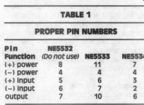
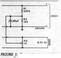
FIGURE 1: Connecting two resistors across the 250V supply can help eliminate parasitic noise.
Finally, two minor errors appeared in my letter. Line 5 (p. 56) should read “...Danish VMS 20, ” not VM520. On page 57, line 6 should read “...crystal controlled ” instead of quality-controlled.
G. Woodville Aylesbury, England HP17 0LY
PAINT UPDATE
IN TAA 5/84 (p. 43), Paul T. Kelly writes about ways to paint an aluminum cabinet. In standard manufacturing processes, special paints are sometimes used directly. In lieu of this, the correct way is a three-step process. First, soak a rag in vinegar (white vinegar is best) and rub it over the entire surface, removing any excess with another rag. This will eliminate the aluminum oxide, which inhibits normal paint from adhering. Second, prime the piece with zinc chromate (available from any paint store
in can or spray form). Once the primer is dry, paint the cabinet with either lacquer or enamel, as desired.
WiLiam R. Horrman; Reno, NV 89502
LOUDNESS CONTROL CALL ANSWERED
I Am writing in response to Dan Wilczek's request for a loudness circuit (TAA 2/85, p. 58). A number of tube units, particularly those by H.H. Scott, feature a switchable, passive loudness control. Probably the most accessible version is the Dynaco PAS type. The manual is available from SCC ( Box 551, Dublin, OH 43017) for $4.50. Radio Shack used to stock (see note below) a 100k “stepped ” (41 detents) dual audio pot ( Alps) suitable for the above (Part No. 271-1732A, $1.79). It has a 40 percent loudness tap.
T. WILBUR; McLean, VA 22101
Many larger Radio Shack stores used to stock the Alps dual audio pot, but several dealers have informed us that it has been discontinued. Some dealers might still have remaining pots in stock, however. -Ed.
SCOPE DOES DOUBLE DUTY
I am interested to know that the “component test ” feature may be used as a transistor and diode curve tracer. I have been using a similar device quite successfully for years. This allows you to identify leads and determine polarity (PNP, NPN) on unmarked units. You may also, of course, determine diode polarity and zener voltage up to the available peak voltage of about 13V.
To set up for these tests, use polarized leads to test jacks. I use black on the left and red on the right, although another unit might not be phased the same and will result in an inverted display. In that case, simply reverse the leads. I like to set vertical and horizontal deflection about equal at 4 to 6 divisions.
Next, take a known NPN silicon transistor, and with the leads connected as in Fig. 1, you will get the displays shown. For PNP, these will be inverted.
A shorted junction will show a straight vertical line, while an open junction will show a straight horizontal line. Note that the voltage swing will not reach the knee on the E-C junction of some units, indicating an open, but if other junctions are okay, chances are it is, too. It is easy to see how you can identify the leads and polarity quickly. If patterns are identical on two units, they should be a good match.
I also use this procedure for checking circuit units. The patterns will be distorted in most cases, but shorted and open junctions will generally be evident.
I am very pleased with this instrument. Calibration is precise, and about the only time I use a frequency counter or voltmeter is to check whether calibration is holding. So far, it has been right on the money.
Don Scott Houston, TX 77087
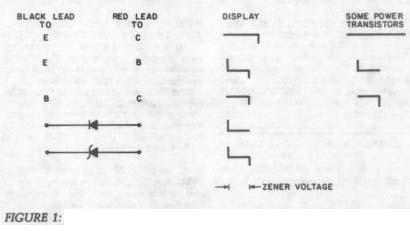
FIGURE 1: Using a silicon transistor, with leads connected as shown, you will get these displays.
----
Also see:
DEPARTMENTS (2/1985)