By Kenneth Beers
I RECENTLY COMPLETED the Jung/Childress POOGE-4 modifications on my Magnavox CDB-560 CD player, using the POOGE-4 articles and the recommended parts (updated according to the Old Colony kit). I performed all modifications on the original Magnavox circuit board, without ‘kludge ’ boards or additional wiring.
Numerous articles and letters in past issues of TAA outline readers' individual approaches to problems and modifications, and I thought that others might wish to try my method.
These mods take some planning, but they can definitely be performed as stated. I have divided my suggestions into three parts.
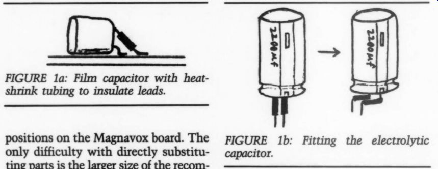
FIGURE 1a: Film capacitor with heat shrink tubing to insulate leads. FIGURE
1b: Fitting the electrolytic capacitor.
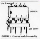
FIGURE 2: Complete module assembly.
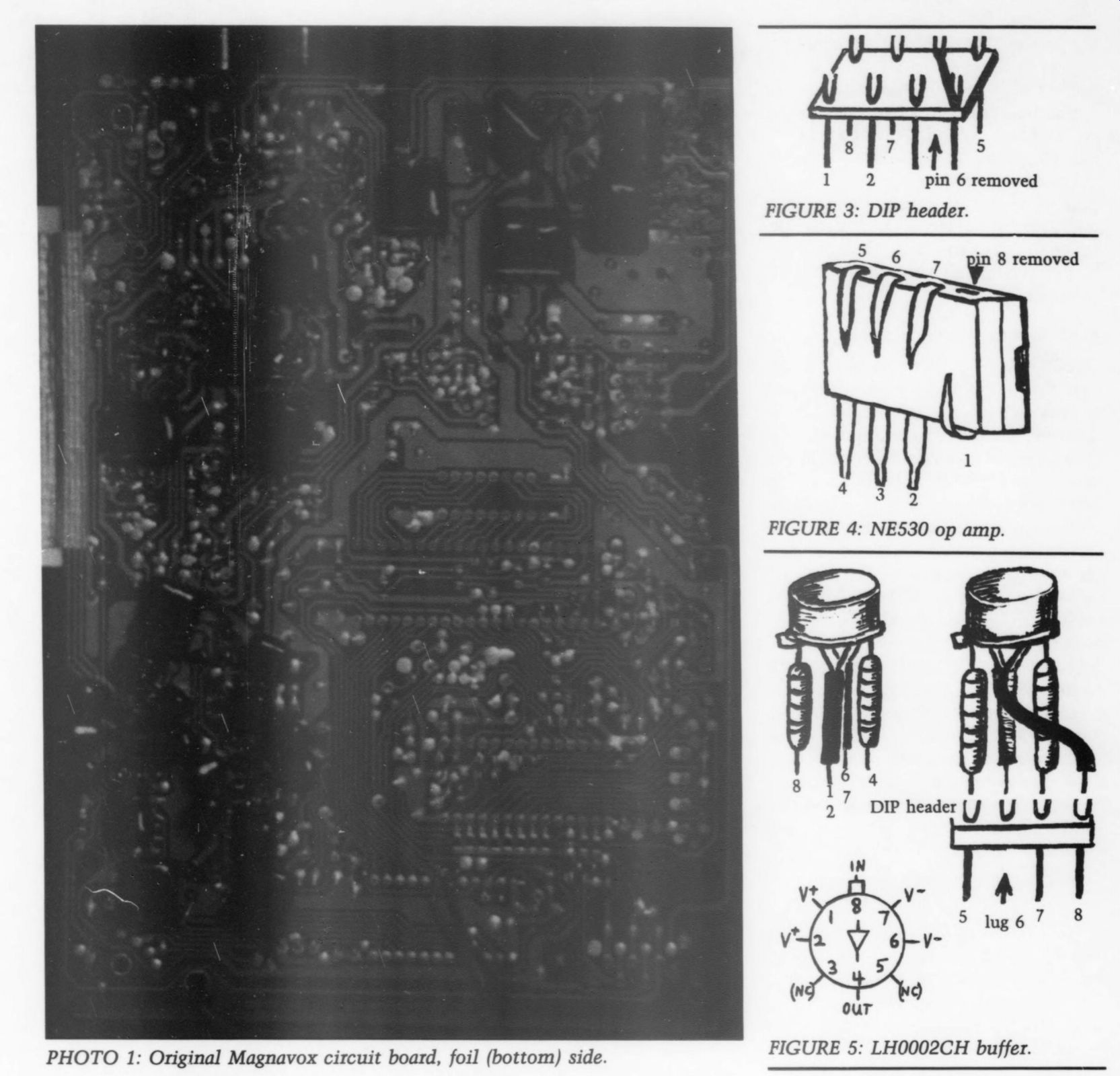
PHOTO 1: Original Magnavox circuit board, foil (bottom) side.
Electrolytics
The replacement metal film resistors and polystyrene capacitors prescribed in the articles will all fit into the original positions on the Magnavox board. The only difficulty with directly substituting parts is the larger size of the recommended 330uF/25V Panasonic HF series bypass electrolytics. I solved this problem by substituting Panasonic HFS series electrolytics (same value and rating). These compact capacitors are only slightly higher in impedance, and fit neatly onto the Magnavox board.
Next, I soldered the Panasonic P series polypropylene film capacitors used for the prescribed bypasses for the electrolytics in place on the foil side of
the board. These capacitors are thin enough so they do not interfere when you re-install the board in the player.
The two large 2,200uF/35V electrolytic capacitors, to be installed on the circuit board near the heatsink, must be off set somewhat from their mounting holes. To do this, insulate the upper % inch of both leads with heat-shrink tubing, bend them to extend beyond the capacitor body's edge, and then fit the device into the available space (Fig. 1b).
Two 330uF HFS types (part 2359, 2364) to be installed near the op amp sockets may need to be offset slightly from their mounting holes to avoid contact with the sockets and installed amplifier modules.
Two 330uF HFS types (part 2325, 2344) near the front right of the circuit board, must be installed lying flat, to avoid interfering with the plastic bracket supporting the small microprocessor board above the main board.
Check the polarity when installing all the electrolytics, and be sure the capacitor leads do not contact the up per copper shielding plane of the circuit board.
------- 1 pin 6 removed
FIGURE 3: DIP header. in 8 removed; FIGURE 4
FIGURE 5: LH0002CH buffer.
------------
DAC
The Panasonic V-series 1uF film cap replacements, for the DAC bit filter 'chip' capacitors, can be installed directly on the foil pads that you expose after removing the original surface mounted ‘chip ’ capacitors from the board. The process is tedious and takes some planning, but it can be done. I in stalled the capacitors flat against the board and insulated the longer leads with heat-shrink tubing (Fig. 1a).
The Panasonic V-series capacitors are not small enough to fit under the re installed board without interference.
You must plan and carefully cut a 6cm by 6cm hole in the plastic bottom of your player. Then, you can glue a flat piece of plastic to the bottom of the player to cover the hole, and allow the necessary 2mm of additional clearance.
Before cutting, thoroughly wrap and cover the left side/mechanism of the player with cloth towels so no plastic dust or filings will get into the laser/ motor/ turntable mechanism. Carefully plan the hole's location, directly under the DAC chip when the board is in place. The hole's front edge should be about even with the short, vertical supporting rib running left to right across the bottom of the chassis.
Drill a pilot hole, then gently cut the hole with a small saw blade, and file the edges. You can more easily cut the hole with a Dremel Moto-Tool and cutting/ filing bits.
I cut a piece of black plastic from the bottom of a Radio Shack ‘hobby box,' and glued it in place with model cement to cover the hole. Finally, thoroughly vacuum all plastic dust from the chassis.
Module Assembly
The POOGE-4 articles outline the de sign of amplifier modules to replace the original Magnavox op amps. These modules are constructed (using Signetics NE530 op amps, National Semi conductor LH0002CH buffers and 1% metal film resistors) on plug-in boards.
I built my amplifier modules on 8-pin DIP headers and installed them in sock ets, located in the original op amp positions. I used the NE530 op amps and LHO002CH (8-pin metal can) buffers prescribed, metal film resistors (UW, 1%), and gold-plated headers and sockets (Fig. 2). I also suggest you use a TO-5 slip-on type, finned heatsink on the LH0002CH case.
As you can imagine, constructing these modules takes planning and careful work, but the results are worth the effort. You will need two modules, assembled as follows:
Step A-preparation of the DIP header (Fig. 3).
1. Clip and remove pin 6 from the underside of the header, leaving the up per solder lug portion in place.
2. Pre-tin all solder lugs.
3. Solder a short piece of bare wire between lugs 4 and 6.
Step B-preparation of the NE530 op amp (Fig. 4).
1. Clip off pin 8 (not used) at the body of the chip.
2. Carefully bend pins 1, 5, 6 and 7 around toward the back surface of the case.
3. Straighten pins 2, 3 and 4 until horizontal to the case; shorten these pins by clipping to 4mm length.
4. Pre-tin all seven pins.
---------------------
FIGURE 6: Primary module assembly.
---------------
Step C-preparation of the LHO002CH Buffer (Fig. 5).
1. Carefully clip pins 3 and 5 (not used) from the device close to the case (check data sheet for pin numbering).
2. Solder pins 1 and 2 (positive supply leads) together close to the case, leaving pin 2 full length. Insulate with heat-shrink tubing.
3. Repeat previous step for pins 6 and 7 (negative supply leads), leaving pin 6 full length.
4. Pre-tin the ends of the previously insulated leads.
5. Clip pin 8 (input, at tab on the case) and pin 4 (output) to 3mm length and pre-tin.
6. Clip the leads of one 100 ohm and one 1 k-O (%W, 1% metal film) resistor to 3mm lengths on each end and pre-tin all four leads.
7. Carefully solder the prepared 1 k-O resistor to pin 8 (tab) of the buffer, over lapping the 3mm portions of each lead.
The resistor should extend vertically below the buffer.
8. Solder the 100 ohm resistor to pin 4 of the buffer (opposite tab) as above.
The buffer should now appear to have four ‘legs. ’
9. Bend and arrange the 'legs' (as shown in Fig. 5) into a linear pattern that will contact lugs 5-8 of an 8-pin DIP header (Step E).
Step D- Primary assembly of the amplifier modules.
1. Solder pins 2, 3 and 4 of the NES530 op amp to lugs 2, 3 and 4 of the DIP header so the chip body is parallel to the surface of the header and about 3mm away from the surface (Fig. 6).
2. Solder a piece of bare wire to pin 6 of the op amp, long enough to run diagonally behind the chip to lug 1 of the header. Slip a short piece of heat shrink tubing over the wire and solder the other end to lug 1. Push this lead flush against the back surface of the chip.
3. Cut the leads of a 499k, ¼ W, 1% metal film resistor to 2mm and 6mm lengths.
4. Slip a 4mm length of heat-shrink over the longer lead and pre-tin each nd.
5. Align the resistor horizontally be hind the op amp case (with the shorter ead toward pin 1). Bend the longer lead around to contact the joint of pin 3/lug 3, and bend the shorter lead and pin 1 of the op amp to overlap each other.
6. Solder the longer, insulated lead o pin 3/lug 3 of the assembly; be careful the joint does not contact pin 4/lug 4.
7. Solder the short resistor lead to pin 1 of the op amp.
8. Solder a 10mm length of bare wire o pin 7 of the op amp, slip a 7mm piece of heat-shrink over the wire and solder the other end to lug 8 of the header.
9. Clip both leads of a 4.99 k-O, %W, 1% metal film resistor to 3mm lengths and pre-tin the ends. Solder this resistor between lug 1 and lug 4 of the header.
(Position the resistor horizontally along the outside edge of the header, in front of lugs 14.)
10. Clip the leads of a 499k, 4W 19% metal film resistor to 4mm and 10mm lengths and pre-tin the ends.
------------------ PARTS LIST
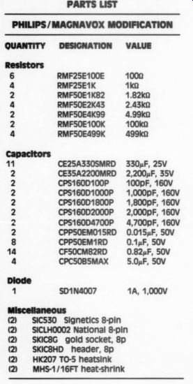
QUANTITY DESIGNATION VALUE
RMF25E100E RMF25E1K RMF50E1K82 RMF50E2K43 RMF50E4K99 RMFS0E100K RMF50E499K 1000 1ke 1.82k0 2.43k0 4.99k0 100k0 499k0
BHBONMNNNNNN CE25A330SMRD CE35A2200MRD CPS160D100P CPS160D1000P CPS160D1800P CPS160D2000P CPS160D4700P CPPSOEMO15RD CPPSOEM1RD CF50CM82RD CPC50B5MAX
330uF, 25V 2,200uF, 35V 100pF, 160V 1,000pF, 160V 1,800pF, 160V 2,000pF, 160V 4,700pF, 160V
0.015 uF, 50V
0.1uF, 50v
0.82uF, 50v 5.0uF, 50V
SD1N4007 1A, 1,000V
Miscellaneous
(2) SIC530 Signetics 8-pin
(2) SICLHO002 National 8-pin
(2) SKIC8G gold socket, 8p SKICBHD header, 8p HK207 TO-5 heatsink
2 MHS-1/16FT heat-shrink
---------------------------
11. Solder the shorter lead to lug 1 of the header (3 leads total should now be soldered to lug 1).
12. Align this resistor parallel to and above the 4.99 k-O resistor (installed in Step 9), against the outside face of the op amp case.
13. Curl the resistor's longer lead up and around the back of the op amp case to overlap pin 5 of the op amp (bend the leads to meet each other), and solder the two leads together behind the op amp case.
Step E-solder the prepared buffer assembly to the header assembly.
1. Bend the buffer assembly ‘legs ’ so they align with lugs 5-8 of the header (see Fig. 5).
2. Solder the 1k resistor ‘leg ’ (tab) to lug 5 of the header.
3. Solder the 100 ohm resistor ‘leg ’ to lug 7 of the header.
4. Solder the negative supply ‘leg ’ (pins 6 and 7) of the buffer to lug 6 of the header. Lug 6 should have a bare wire soldered to lug 4; no pin extends below the header.
5. Bend the insulated positive supply 'leg' (pins 1 and 2) of the buffer across in front of the 100 ohm resistor ‘leg ’ and solder the end to lug 8. (Two leads should now be soldered to lug 8.) This completes the amplifier module assemblies. Install the modules in gold plated sockets, located where the original op amps were removed from the Magnavox board.
Construction Hints
I built my original amplifier modules with AW resistors, but unless the resistor leads are trimmed fairly short, they extend beyond the buffer leads and may not meet the DIP header lugs exactly as shown in Fig. 5. Smaller 4W resistors could make the construction less tricky, but AW devices will work fine.
Regarding the original Old Colony POOGE- 4 parts kit, I noticed a discrepancy between the number of bypass capacitors supplied and what is recommended in the POOGE-4 article. That kit supplied only three 0.1uF caps, to shunt the three new 330uF HF caps in the DAC supply lines; however, to perform all the bypasses, you need eight 0.1uF devices-one for the main +5V supply, four for the op amp supply lines, as well as the three for the DAC lines. I used a total of 12, as shown in
Photo 1, to shunt several other power supply electrolytics.
In ‘POOGE-4,' Part 1 (TAA 1/88, p. 12), the paragraph describing power supply line connections to the DAC is confusing. The authors describe the exact changes to make to the capacitor bypasses, but do not clearly explain what you must do with the decoupling resistors. Make the specific changes, as follows:
Replace the 4.7 ohm resistor (part 3330) in the +5V DAC supply line with a wire jumper.
* Replace the 10ohm resistor (3332) in the -15V line with a wire jumper.
* Replace the 10 ohm resistor in the -6V line with a 1IN4002 rectifier diode, installed with the cathode (banded end) toward the power supply. The diode drops the -6V supply closer to the -5V specified for the DAC chip.
Old Colony's new kit, the KY-1: Beers' Budget CD Mod, is now available for $95. All parts are included; circuit boards are not required.
-------------------
Also see: