Recent technical advances in the field of two-way radio have resulted in vastly improved equipment design. Modern two way radios are much smaller and consume less primary power than their predecessors. For example, a mobile two-way radio now takes up less space than a small overnight case and consumes less battery power than the headlights of the automobile.
Moreover, it is quite easy to install and remove for servicing.
Since only one two-way radio is no better than a disconnected telephone, a second radio is required on the same operating frequency to establish communications. Usually there is a main two-way radio centrally located in the desired area of coverage. It is a stationary type and is aptly referred to as the "base station," since it is generally the one from which most communications originate.
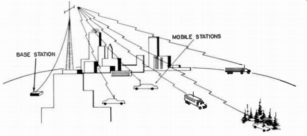
Fig. 1-1. Relationship between base and mobile stations.
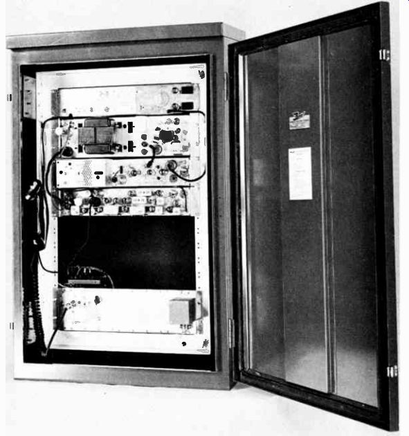
Fig. 1-2. Typical 60-watt base station.
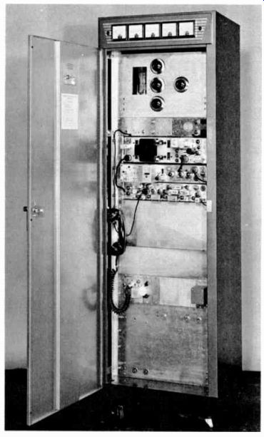
Fig. 1-3. Typical 250-watt base station.
A two-way system may consist of any number of base or mobile units. Most are comprised of one base, and several mobile stations. Fig. 1-1 shows that the mobile units are free to move about the centrally located base station without losing radio contact. The farther apart the base and mobile stations are, the weaker the received radio signal becomes. Moreover, weak signals are sometimes blocked completely by intervening buildings, terrain, etc., thus resulting in complete loss of communications.
Figs. 1-2 and 1-3 show typical 60- and 250-watt base stations, respectively. In contrast, a mobile two-way radio appears in Fig. 1-4. Notice how conveniently this small mobile unit fits into the trunk. It can also be removed from the trunk and used for portable operation (Fig. 1-5). Both the base and the mobile units are capable of receiving as well as transmitting a signal.
Fig. 1-5. The two-way radio of Fig. 1-4 can also be used as a portable
station.
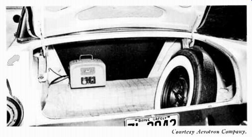
Fig. 1-4. A trunk-mounted two-way radio.
HOW FM TWO-WAY RADIO OPERATES
Two-way radio is comparable to a telephone system except there are no interconnecting wires. In fact, two-way radio is often called radiotelephone. A telephone mouthpiece and a microphone are practically the same, and in many cases, electrically they are directly interchangeable. The microphone converts the voice into small electrical impulses, which are amplified and used to vary (modulate) the frequency of a carrier signal generated by the transmitter oscillator. It is the amplified latter signal that carries the electrical equivalent of the voice through the air to the receiving station. Here the trans mitted wave is picked up by an antenna and fed into the receiver, where it is amplified and the voice signal recovered from it much as in a conventional radio. Ultimately the message is heard through the speaker.
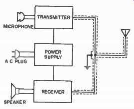
Fig. 1-6. Block diagram of a two-way radio system.
Fig. 1-6 shows the three basic sections to the complete two-way radio. These are a transmitter, receiver, and power supply. The only basic difference between a base and mobile station is that a base station operates from the standard 110-volt AC line, whereas the power supply of a mobile station relies on energy from the automobile battery. In either case, the radio power supply is designed to supply the necessary operating voltages. The transmitter and receiver sections of the base and mobile units are directly interchangeable. The only section not interchangeable is the power supply. In present-day two-way radio equipment, a single power supply provides the proper operating voltages for both the transmitter and receiver.
The transmitter to which this voltage is supplied amplifies the voice signal from the microphone and provides it with a radio-frequency (RF) carrier signal capable of being radiated from the antenna. The receiver, on the other hand, selects and amplifies the correct RF carrier (out of the countless number existing in space). Then it separates and amplifies the audio (voice) signal originally produced by the microphone. Finally, the receiver converts the audio signal, by mechanical means, back into sound waves that can be heard and understood.
Notice that both the transmitter and receiver use the same antenna (Fig. 1-6). A relay arrangement automatically switches the antenna from the receiver to the transmitter circuitry whenever the push-to-talk button on the microphone is de pressed. This will be covered later in another section.
REMOTE CONTROL AND POWER CABLING
Two-way radio equipment is generally mounted as near the antenna as possible, especially in the case of base stations.
Usually this places the radio equipment some distance from the control point, so that some form of remote control is required.
There are two basic reasons for remoting base-station equipment. First of all, seldom is there adequate space for a cumber some radio cabinet in the room where the operator sits.
Secondly, by locating the base equipment close to the antenna, a shorter length of transmission line is required. This is important because the RF signal loss incurred in the line increases with the length of the line. Therefore, the shorter the over-all distance between the transmitter and antenna, the lower the line losses, and thus the more radio-frequency energy radiated from the antenna.
Remote-Control Amplifier
When the radio equipment is to be remote controlled, an amplifier must be employed to boost the strength of the audio signals going to the transmitter and coming from the receiver.
This amplification is necessary because the electrical signal produced by the microphone is weak to begin with, and in most remote systems there is enough loss in the lines between the microphone and the transmitter to effectively "dissipate" a weak signal. An insufficient microphone signal will result in poor reproduction of the voice at the receiving station, and if too weak, could permit noise to be amplified and transmitted along with what little audio voltage did get through. The received message then would be so weak and scratchy that communications would be very poor. To overcome this condition, the microphone is directly connected to a remote-control amplifier (Fig. 1-7) , which boosts the microphone voltage more than enough to offset any losses incurred in the control lines feeding the transmitter. With more than sufficient audio signal being applied to the transmitter, the voice heard at the receiving station will be loud and clear.
In addition to amplifying the signals from the microphone, the remote-control unit also amplifies the audio signals en route from the receiver to the speaker (located at the control point) , and is even used in conjunction with similar units as an intercom system. In many models, "alert" tones (to indicate that a message will follow) can be generated and transmitted over the air by pushing a single button. The remote-control unit also has provision for activating the transmitter to put messages on the air. The transmitter is normally in a standby condition, allowing incoming signals to be received. When it is activated to make a transmission, the receiver is automatically disabled.
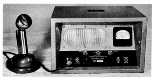
Fig. 1-7. A typical remote-control amplifier.

Fig. 1-8. Base-station intercabling.
Fig. 1-8 shows an intercabling diagram of a remote base station system. Only two wires are used to perform the functions just described. This is made possible by applying the amplified microphone signal (AC) to the same wires that carry DC from the remote amplifier to the remote-control chassis to operate the transmitter relays. A schematic of a remote-control amplifier is shown in Fig. 1-9. When the micro phone "push-to-talk" button is depressed, relay M1 is energized and switches the amplifier circuit from the "receive" to the "transmit" mode.
The microphone signal is coupled from the mike plug, through mike gain control R1, to the first audio amplifier (V1A). Here the signal is amplified and passed along (M1 con tact 6 is shown in the "receive" position) , to be further amplified by V1B and V2. The now strong audio signal is coupled to the L2 secondary winding of transformer T1. From here the signal is fed, via M1 contacts 7 and 9, to the L4 portion of the T2 primary, and then appears at the L5 and L6 secondaries of this transformer. L5 and L6 are directly connected to the control lines at an appropriate terminal board.
At the time relay M1 was energized and all its contacts (shown by dotted lines) were transferred, DC voltage was then taken off the cathode of V4A through contacts 2 and 3 and applied to the control lines at L5 and L6 of T2. This voltage is impressed on the lines connected to the transmitter. In the transmitter, a relay is energized by this DC voltage. Its contacts actually control the operation of the remote transmitter.
When the microphone "push-to-talk" button is released, relay M1 drops out and the amplifier circuit returns to the normal "standby," or receive position. At this time, any in coming audio signal on lines 1 and 2 (from the base receiver or another remote unit) is transferred to the amplifier circuit through the L4 and L5 secondaries to the primary of T2.
From here the audio signal is fed to the volume control by way of M1 contact 8. The signal developed across this control is amplified in V1B and V2, and then coupled into T1. The M1 contacts are now in the receive (R) position as shown, so the amplified audio is heard through the speaker.
The power-supply section is straightforward. Full-wave rectifier V3 supplies more than enough voltage to power the amplifier, and a very efficient filtering system keeps AC ripple practically non-existent. If ripple were to be introduced into this unit, it could cause hum in the transmitted signal.
Tubes V4A and V4B adjust the DC control voltage to the desired value, according to the transmitter used.
Base-Station Relay Control
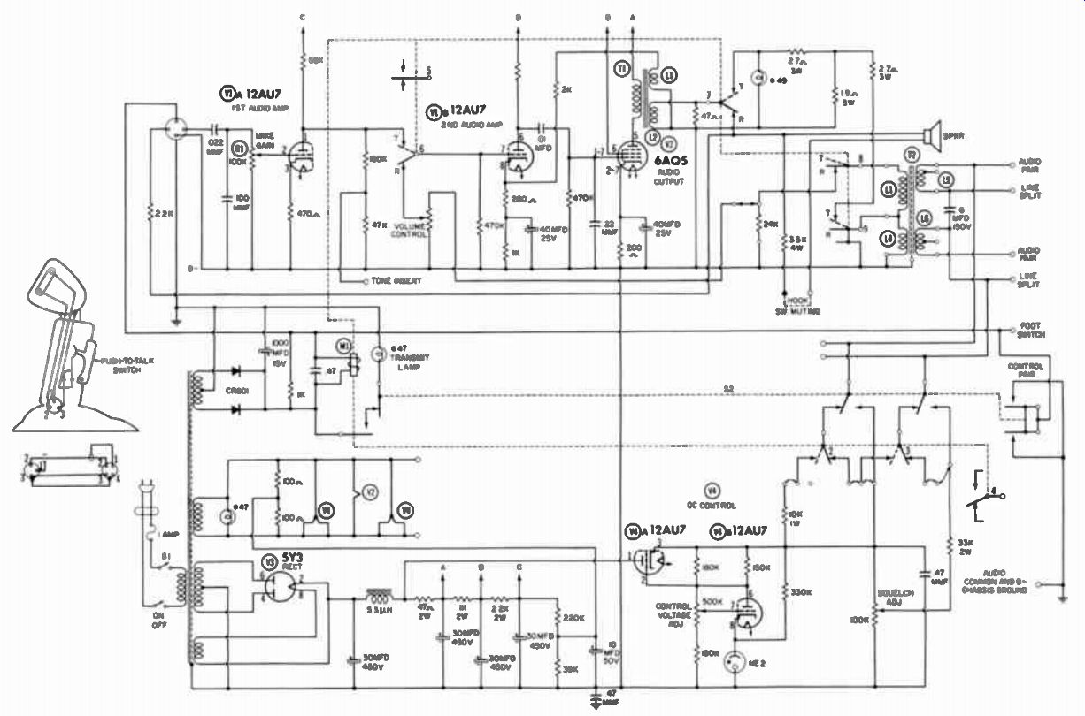
Fig. 1-9. Schematic of a GE remote-control amplifier.
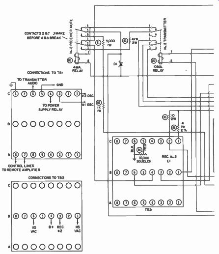
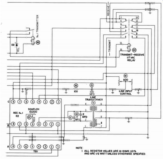
Fig. 1-10. Schematic of a remote-control chassis.
NOTE 1: ALL RESISTOR VALUES ARE IN OHMS at 10% AND ARE 1/2 WATT UNLESS OTHERWISE SPECIFIED
By using a system of relays, the transmitter and receiver of a base station can be controlled directly from the remote control amplifier. When the DC voltage from this amplifier is impressed across a relay in the "remote-control chassis," the relay is activated and transmitter operation is initiated. The remote amplifier and the transmitter are now directly connected, and the amplified microphone signal is as strong as, or stronger than, if the microphone output were fed directly into the transmitter. When the DC voltage is removed from the line ("push-to-talk" button released) , the control relay returns to its normal resting condition. This disconnects the transmitter input and connects the audio output of the receiver to the control lines. The audio signal is then fed into the remote control amplifier, where it is boosted in strength and then converted into sound energy to enable the dispatcher to hear the incoming message.
The heart of the base station is the remote-control chassis itself; it controls the transmitter, receiver, and power supply.
For the sake of illustration, the transmitter output and the receiver input were shown as being connected together in the block diagram of Fig. 1-8. In reality, a relay connects the antenna to either the transmitter or receiver circuit, de pending on the operation desired. In other words, when the microphone button is depressed, the relay is automatically energized and switches the antenna into the transmitter circuitry. Conversely, releasing the mike button returns the relay to its normal resting position, whereby the antenna is connected to the receiver circuit.
In Fig. 1-10 the lines coming from the remote amplifier are connected to terminals 7 and 8 of TB1-A. Transformer T1 has one end of each primary winding connected to terminals 7 and 8; therefore, the incoming voltage through these windings appears at TB1-A1 and 2. From terminal Al the voltage (negative) causes current to flow through diode D1, relays M3 and M2, and then back to TB1-A2, which is positive. This current flow is sufficient to energize only relay M3 but not M2 (unless the No. 2 frequency is selected at the remote amplifier). It takes only 45 volts DC to produce enough current to activate 4-ma relay M3, while M2 (the 10-ma relay) requires 100 volts DC or more. However, when there is sufficient current to energize M2, M3 is also energized. Where only M3 is activated, contacts 5 and 6 complete the 117-volt AC circuit through transmit-receive relay M4. M2 contacts 1 and 2 are in series between ground and the transmitter No. 1 oscillator cathode. When M4 is then energized, the relay in the base-station power supply transfers its contacts and the transmitter is put on the air on frequency No. 1.
Notice the shielded wire connected to terminal 9 of the T1 secondary winding. The incoming audio-modulation signal is fed to this winding and is sent into the transmitter through the M4 contacts, line input control R9, C3, R8, and TB1-C6. The audio return path is through common ground. In this remote chassis, the line input control is of the pad type. As the control is adjusted in either direction, the amount of audio across it is changed correspondingly. However, the impedance of the circuit is not upset by this adjustment, as it would be if an ordinary potentiometer were used. Any such impedance change would cause distorted audio to be delivered to the transmitter, and the result would be indistinct modulation.
If the radio operator (at the remote amplifier) desires to transmit on frequency 2, he merely flips the frequency switch on the amplifier case itself. (This switch determines whether 45 or 100 volts DC is impressed on the control lines.) Now, when he depresses the push-to-talk microphone switch, relays M2 and M3 (in the remote-control chassis) will both be energized. Relay M3, of course, will pick up M4 and in turn place the transmitter on the air. Relay M2, however, now transfers its contacts 2 from 1 to 3. This removes the ground from the No. 1 oscillator in the transmitter, and connects the cathode of oscillator No. 2 to ground. Thus, the operating frequency of the transmitter is changed, and the operator is talking on a different channel.
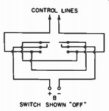
Fig. 1-11. Polarity-reversing switch connections.
In base stations equipped to receive two channels at the same time, Channel 1 almost always takes precedence over Channel 2; therefore, sometimes it is necessary to quiet Channel 2 in order to hear Channel 1. This is done by depressing the Channel 2 Mute switch located on the remote amplifier.
The switch reverses the polarity of the voltage on the control lines. This feature is not included on the model in Fig. 1-10; however, Fig. 1-11 shows a simulated circuit for voltage polarity reversal. With the polarity of the control voltage re versed on the control lines, the voltage at TB1-A1 will now be positive and TB1-A2 negative. This means that D1 will block the positive voltage on TB1-A1, and relay M1 will be energized. As the M1 contacts are switching, contacts 2 and 3 make before 4 and 5 (pickup circuit) break. This establishes a constant voltage path from TB2-B4 through M1 via contacts 2 and 3 of MI. and 4 and 5 of M2. The return path from M1 is through D2 (this prevents relay M3 from being activated) and M2. M2 will not be activated because it requires 10 ma of current to do so, and only 4 ma is flowing. When M1 contacts 1 and 2 open, the B+ path to receiver No. 2 is broken. This, of course, "kills" the second receiver, leaving only receiver No. 1 operating. Since the holding path from M1 (receiver No. 2 mute) is through M2 (transmitter No. 2), after M2 has been energized, receiver No. 2 is again active.
This completes the discussion on the remote-control amplifier and remote chassis. You can see that any necessary transmitter or receiver operation can be conveniently performed from the remote amplifier. Not covered in this discussion is the added feature of "tone alert," which is simply a one-tube low frequency oscillator incorporated in the remote amplifier.
Through an appropriate switching arrangement, this tone (approximately 100 hz) is fed into the control lines just like the microphone audio. This alert is generally used to call attention to a forthcoming message to be transmitted.
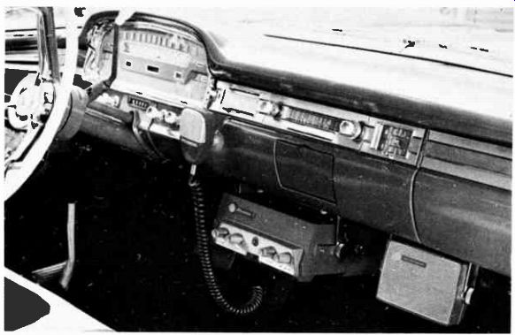
Fig. 1-12. A transistorized GE dash-mounted two-way radio.
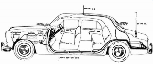
Fig. 1-13. Cutaway view of automobile, showing trunk-mount installation.
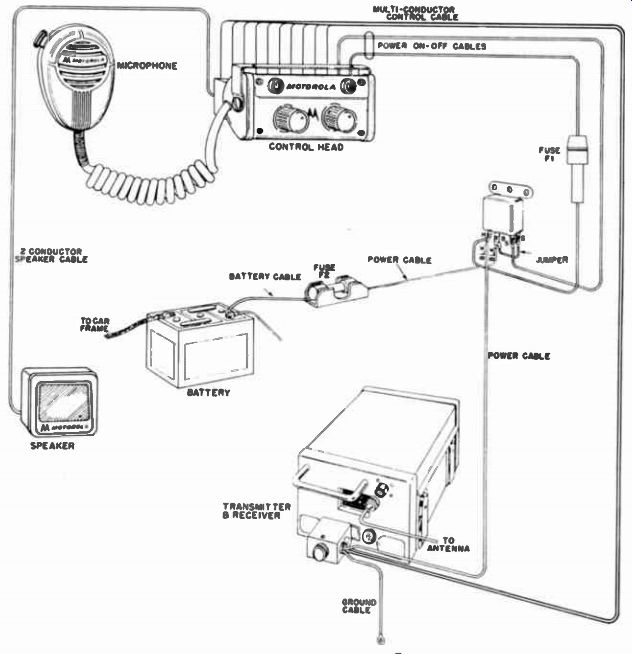
Fig. 1-14. Detailed inter-cabling arrangement for a typical mobile two
way radio installation.
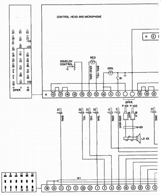
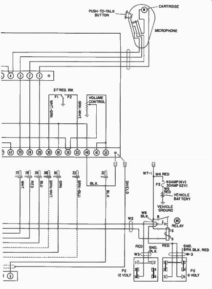
Fig. 1-15. Schematic of a Motorola control head.
Mobile-Station Control
Basically, there is no difference between the operation of a base and a mobile station. Some mobile radios are designed to be mounted in the trunk, as shown previously, while others are mounted under the dashboard of the car (Fig. 1-12). The front-mount (dash-mount) type has the controls right on its cover. Fig. 1-13 is a cutaway view of an automobile, showing a trunk-mounted two-way mobile-radio installation; and Fig. 1-14 shows a more detailed view of the system. Notice the arrangement of the control head and radio. Since the radio and the operator are only a few feet apart, there is very little loss in the cabling and therefore no need for a remote amplifier.
A typical schematic of a mobile control head is shown in Fig. 1-15. When Si (on-off switch) is turned on, the circuit is completed from one side of the car battery to the other side (ground) through power relay M1. The resulting current flow through M1 energizes it, causing its contacts to transfer and thereby completing the circuit from the battery to the power supply. The purpose of the power relay is to handle the heavy current flow (as high as 30 to 40 amps during transmitting) in the power cable. If this current were to be passed through the on-off switch itself, the switch would soon burn out. So, in order to present a small control head (instead of using a - large switch to turn on the radio directly), this method is employed. Now, on-off switch S1 need pass less than 1 amp of current, for that is all the relay pulls.
A green lamp on the control-head panel indicates when the power is on, and a red one indicates when the transmitter is on the air. Notice the two-frequency switch, squelch, and volume controls. Every control necessary for 100% two-way operation is included in this one control box. All wiring from the control head to the radio is through a cable approximately 15 feet long terminated in a plug (P1) connected to the front of the radio itself, as shown in Fig. 1-14.
Also see: