A new era in broadcasting was ushered in with the FCC approval of fm stereophonic broadcasting in April, 1961. This system provides high-fidelity stereophonic sound while preserving compatible monophonic reception for existing single-channel receivers. Provision is also made to preserve SCA (store-casting) service simultaneously with stereo programming.
Stereo-casting provides a fair approximation of listening in person. In nature, the spacing between our ears enables us to localize directions from which sound emanates. Part of this effect is the result of a few milliseconds delay of a sound wavefront from ear to ear. Higher frequencies have wave lengths near or less than the ear-to-ear spacing, resulting in phase differences. The combination provides depth and is missing in monophonic transmission, in which all microphones are mixed into a single channel.
The stereo system provides this depth by means of separate left and right channels that are reproduced by corresponding left and right speakers. The "center" is provided by effect only, as when a single sound source is of equal intensity and in phase on both channels. This is like mono phonic reproduction by two or more speakers.
The number one requirement is compatibility. This means that:
1. A standard receiver can reproduce a monophonic output from a stereocast, without loss of original program information.
2. A stereo receiver can reproduce a monophonic program without loss of original program information.
The two separate audio channels are encoded into a composite signal at the fm transmitter, as fully explained in Section 10. In this Section, only the studio terminal of the complete stereo system will be discussed, along with existing and proposed quadraphonic systems.
The most obvious difference is that two separate channels, left and right, are involved for a single stereo program. For live pickup, one or more microphones are employed for the left channel and one or more for the right channel. Reel-to-reel or cartridge tapes for stereo employ two-
track tape and two heads. Stereo disc recordings are reproduced by means of the conventional stereo pickup head feeding a stereo preamplifier which has left and right-channel outputs.
7-1. THE STEREO CONSOLE
Fig. 7-1 illustrates the CCA Ultimate stereo 10-channel control console.
Fig. 7-2 is a highly simplified block diagram of the console. The designation by symbols of the buses near the center of the diagram is as follows:
PL: Program left
PR: Program right
AL: Audition left
AR: Audition right
C: Center (Feeds combined left and right channels)
Input circuits include six microphones switchable to two faders, two turn tables, ten high-level lines switchable to four faders, one external monitor input, three remote lines, and three cartridge lines. A description of each of the channels follows.
Courtesy CCA Electronics Corp.
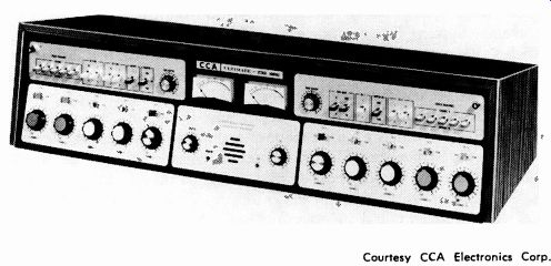
Fig. 7-1. CCA Ultimate stereo control console.
Channels 1 & 2 (Stereo Auxiliaries)
Channels 1 and 2 are high-level stereo channels that have five high-level stereo inputs available which can be switched to either of the two stereo channels. It is impossible for the same input to be connected to both faders simultaneously, and thus segueing between the two channels with the five high-level inputs can be accomplished. Each stereo fader is of Altec manufacture with removable covers for cleaning; each contains a cue position.
The output of each channel is switched to either the stereo audition or program lines.
Channels 3 & 4 (Microphone Channels)
Channels 3 and 4 each have available three inputs which in turn are used to drive monophonic preamplifiers that can be used to feed either the left or right amplifier or both in parallel. This selection can be achieved by means of a front-panel switch.
These inputs are nominally 200 ohms and are designed to accept input levels of -50 dBm. The three inputs are fed to the input selector switch, which in turn selects an appropriate input to drive the preamplifier. The output of the preamplifier is controlled by a fader which is so identified on the front panel of the console. The output of this fader, by the appropriate switch position identified as center-channel switching, can be directed to either the left, right, or center channel. From the output of this channel-selection switch, the signal is then fed to the audition-program switch. This switch is located just above the individual channel gain control.
Channels 5 & 6
Channels 5 and 6 are high-level stereo channels recommended to be used as turntable inputs for both the conventional left and right turntables. In order to achieve the optimum in signal-to-noise ratio, it is suggested that equalized preamplifiers for the turntables be installed in the turntable housings.
Channel 7
Channel 7 is a high-level stereo channel that has three switchable inputs and is suggested as a channel for stereo cartridges. It contains a cue position, and its output may be switched to either the audition line or the program line.
Channel 8
Channel 8 is available to be used as a remote high-level monophonic channel. It contains facilities for selecting one of three inputs and feeding the output of the fader to either the left, right, or center channel. This channel also contains facilities for talk-back.
Channel 8 in the console has essentially the same characteristics as channels 3 and 4 except for the fact that it does not have a preamplifier. It accepts a high-level input and feeds a transformer. This transformer isolates the source from the console. The output of the transformer is fed to a front-panel fader, then to the left-center-right switch, and then finally to the audition-program switch.
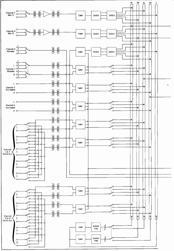
Fig. 7-2. Simplified block diagram, CCd Ultimate stereo control console.
Channels 9 & 10
Channels 9 and 10 are similar in construction and philosophy to channels 1 and 2. They are high-level stereo channels with facilities to select any one of five high-level stereo inputs for either of the two channels. It is impossible for both channels to be fed with the same input simultaneously. This philosophy provides a foolproof method of switching between two channels without causing an attendant drop in the audio level of the program.
Isolated High-Level Inputs
Transformers are used in every high-level input. This prevents problems associated with ground loops.
Program Channel
Assuming that the audition-program channel switch is in the program position, the output of the channel is connected to the program line. In the case of the monophonic inputs, when the switch is in the center-channel position, both the left and right program lines are fed in parallel. In the left position, only the left channel is fed, and in the right position only the right channel is fed. In the stereo mode, both the left and right booster amplifiers are fed.
The outputs of the booster amplifiers are then used to feed the front-panel master faders, both left and right, which in turn feed the line amplifiers. The outputs of the line amplifiers are available to feed either line 1 or line 2; in the center position, the console is self-terminated. Thus it is possible to disconnect the console from its terminating lines and still evaluate its performance by having it self-terminated.
Audition Channel
With the audition-program switch in the audition position, the outputs of the individual channels are fed to the audition booster amplifiers. The outputs of these booster amplifiers are used to feed an external set of terminals or, through the appropriate monitor selector switch, the monitor amplifiers. The audition channel does not have any individual master controls.
The output level is controlled by the individual dual channel masters. With normal settings of the individual channel controls, -10 dBm will appear at the audition output terminals.
Cue Channel
Other than channels 3 and 4 (microphones) , every fader in the console (8 faders) contains a switch position that connects the input signal to the cue bus. The cue bus normally feeds the cue amplifier through the contacts of the talk-back relays. Thus, the cue bus cannot inadvertently feed a speaker when the microphone is live.
The cue speaker is driven from the cue amplifier through the talk-back relay contacts and the control-room mute relay contacts. Under the condition of talk-back, the cue-amplifier input and output circuits are reversed, and it is used to amplify the output from the front-panel speaker which, in the talk-back position, serves as an audio source rather than a termination. The cue amplifier has capabilities of achieving 8 watts output, and its module is identical to that of the monitor amplifier.
A front-panel jack is used for monitoring with earphones. The cue amplifier is related to the left channel only.
Stereo Monitoring
The monitoring system has facilities for monitoring, on a stereo basis, the main channel, the audition channel, and external off-air programs. By the use of a front-panel selector switch, the monitor amplifier can be fed from the program line, the audition channel, or an external audio input.
It contains a stereo fader for both the left and right channels, and its output is connected to three sets of speaker systems through the speaker-mute relay panel. It also has facilities for driving the front-panel monitor phone. It is designed basically to feed low-impedance devices; thus the monitor phone should have an impedance of approximately 8 ohms, and the speaker impedance should be approximately 24 ohms ( three speakers in parallel across the 8-ohm monitor output: one each in studio A, studio B, and the control room). It is capable of producing 8 watts output to both the left and right channels under normal drive conditions.
Auditioning Without Monitor Amplifier
The console contains booster amplifiers in its audition lines. Thus, it is possible to audition a number of program sources and obtain an output level great enough that the monitor amplifier is not required. This addition of booster amplifiers in the audition channel adds considerable versatility.
Center Channel Control and Switching
The output of the center channel can be switched to either the audition or program channel, and the levels available to both the left and right channels are controllable. Controllable center channels are available not only from the low-level microphone channels but also from a high-level channel.
Channels 3, 4, and 8 contain facilities for feeding the outputs of the pre amplifiers and the independent high-level inputs to either the left, right, or center channel, as the result of the appropriate selection of the individual channel selector switch above these channels. When the switch is placed in the center-channel position, the output of the switch is connected to two individual potentiometers that are mounted on the tray behind the front panel. These controls are pre-adjusted to achieve equal output level on both lines. They drive individual Altec 1578A booster amplifiers. The outputs of these booster amplifiers are used to feed an audition-program switch for the center channel. By turning the switch to the audition position, both the left and right audition channels are driven; when it is placed in the program position, the left and right line amplifiers are driven.
Switchable Output Lines
The console has front-panel facilities to switch the output to a second pair of stereo lines. This can serve as an emergency output in the event that the terminal equipment driven by the normal output becomes defective and the alternative output could be used to drive the proper termination for the console.
Microphone Preamplifier
The console contains two microphone preamplifiers. From Fig. 7-3, it can be seen that the preamplifier consists of two individual modules.
They are an rf filter and an Opamp Lab 350P preamplifier. Both of these modules are located on the shelf behind the control panel.
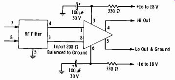
Fig. 7-3. Preamplifier for microphones.
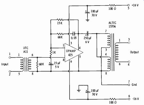
Fig. 7-4. Circuit of line amplifier.
The purpose of the rf filter is to minimize rf overloading of the pre amplifier. This feature is particularly important when the installation is close to the transmitter, where a large rf field may exist.
The Opamp Lab 350P operational amplifier has a fixed gain of 50 dB.
The input impedance is fixed at about 200 ohms and is electrically balanced to ground. The amplifier is capable of a +12-dBm output before clipping occurs, which means the input signal may be as large as-38 dBm.
Equivalent input noise is less than-120 dBm in the band of 30 Hz to 15 kHz. Being an operational amplifier with a bipolar power supply, the amplifier is insensitive to power-supply noise.
Program Line Amplifier
The line amplifier (Fig. 7-4) is built around an Opamp 425, which has an open-loop gain of 20,000. The UTC All and Altec 15356 transformers provide impedance matching and a balanced line in and out. The gain of the unit may be adjusted by changing the 15K feedback resistor. Since it is a bipolar operational amplifier, the unit is insensitive to power-supply noise. With an input level of-30 dBm, the amplifier can achieve a distortion-free output of +14 dBm.
Both a left and a right line amplifier are used. These units are of a plug-in variety and are located on the rear base of the cabinet.
7-2. STEREO MICROPHONE INPUTS
Fig. 7-5 illustrates the microphone input circuitry of the stereo console described above. Note the arrangement of the microphone switch which selects the microphone from studio A, control room (CR) , or studio B.
The switches are shown in the A position. Note also that a set of contacts on each switch runs to the program-audition switch so that this switch must be moved from the center position to select either program or audition before the speaker-muting and on-air light circuitry is activated.
For stereo broadcasting, it is extremely important that the left and right program sources be in phase with each other for correct aural perspective.
When inputs are connected to a stereo console, color coding of the micro phone pins and microphone cables must be observed so that they are connected to corresponding terminals on the terminal board of the console.
All microphone manufacturers give the polarity of their particular models for correct phasing. For example, Fig. 7-6A shows this information for the E-V Model 666 microphone. Positive pressure on the generating element results in positive voltage on the red cable lead (pin 1) relative to the black cable lead (pin 2) . For the Shure Model SM 58 (Fig. 7-6B) , positive pressure produces positive voltage at pin 2 (blue) with respect to pin 3 (red).
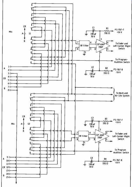
Fig. 7-5. Microphone input circuitry. (A) E-V Model 666. (B) Shure Model SM
58.
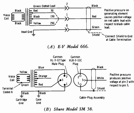
Fig. 7-6. Examples of microphone wiring.
The above example illustrates the amount of thought that the stereo technician must give to the installation and usage of microphones. Review Fig. 6-50 of Section 6. The studio wall microphone outlets are wired in a consistent manner into the rack or console preamplifiers. In Fig. 6-50, pins 1 and 2 are the signal leads, and pin 3 serves as the ground carry-through.
This means that if you employ different makes and models of microphones, you must adapt the microphone cable for proper phasing of all micro phones.
The color coding of shielded two-wire cable is black-white-shield or black-red-shield. The color coding of shielded three-wire cable is usually black-red-green-shield. Let us now review how to handle different types of microphones for the installation of Fig. 6-50, with either two-wire or three-wire shielded microphone cable (plug end for wall outlet) .
For the EV Model 666 (Fig. 7-6A) and shielded two-wire cable with black and white wires, connect black to pin 1, white to pin 2, and shield to pin 3. This carries out the usual power-line color coding in which black is always "hot" with respect to white. For two-wire shielded cable with red and black wires, connect red to pin 1, black to pin 2, and shield to pin 3.
For three-wire shielded cable with black, red, and green wires, connect red to pin 1, black to pin 2, green and shield to pin 3.
For the Shure Model SM 58 (Fig. 7-6B) and shielded two-wire cable with black and white wires, connect black to pin 1 at the wall-outlet plug end of the cable and to pin 2 at the microphone end of the cable. Connect white to pin 2 at the wall-outlet plug end and to pin 3 at the microphone end of the cable. Connect the shield to pin 3 at the wall-outlet plug end and to pin 1 at the microphone end of the cable. For two-wire shielded cable with black and red wires, connect red to pin 1 at the wall-outlet end of the cable and to pin 2 at the microphone end of the cable. Connect black to pin 2 at the wall-output plug end of the cable and to pin 3 at the micro phone end of the cable. Connect the shield to pin 3 at the wall-output plug end and to pin 1 at the microphone end of the cable.
Note that when different-type microphones may employ the same type (usually XL) of connectors for both ends of a cable, the cables must be identified to maintain proper phasing. The same attention must be given to microphone extension cables.
NOTE: In many instances, the microphone head receptacle (when used) may be rewired at the microphone end for the system configuration. In other instances, all microphone cables are wired the same, and short identifiable adapter cords are inserted for a particular microphone. Micro phones with heads that have a cord running from internal wiring can, of course, have the cord-plug wiring modified to suit any system configuration.
Upon initial installation of a control console, the wiring from the studio microphone outlet receptacles into the preamplifiers must be made consistent. For example, in Fig. 7-5, if the studio A microphone is wired so that the positive terminal is connected to terminal 1, the positive terminal of all other outlets must go to terminal 9 of the second switch, etc.
7-3. WHY QUADRAPHONIC?
We have just two ears, and the question inevitably arises in the new comer's mind as to the necessity for four-channel sound reproduction. In monophonic broadcasting, even though two microphones might be used spaced apart the same distance as the average set of human ears, there is no information in the signal as to directional properties of the two micro phones. Regardless of the number of microphones employed in the pickup, the information is the same in all reproducers regardless of the number of speakers used. Certainly you can get "surround sound" in monophonic re production by using four speakers-left front, right front, left rear, and right rear. But there still is no directional information in the single-channel sound from the four speakers.
In stereo broadcasting, two channels designated "left" and "right" are employed. Two separate bits of information are available to the stereo receiver so that these two channels are reproduced through two sets of speakers, imparting directional sound perspective to the produced signal.
When you attend a live sound performance, it is true that your two ears do pick up certain magnitudes of direct sound from left and right. But almost 75 percent of the sound you actually hear is reflected from the side and rear walls, the ceiling, and even objects and people. Again, even though a number of microphones are split into two groups for "left" and "right" signal information, and even though these microphones are arranged to pick up reflected (ambient) sound, only two bits of information are present for the stereo receiver to interpret. The direct and ambient sound are channeled into just two groups (left and right), and there is no separate information to distinguish direct from ambient sound.
The problem (and even the solution) is very much like that of color television. Even though a monochrome camera looks at the colors in the original scene, there is only brightness information in the signal, which carries no color information for use by a color receiver. The color information must be separately encoded (onto a subcarrier) and interleaved into the tv-channel bandwidth employed for regular monochrome broadcasting, so that the color receiver can use this information to reproduce the original scene, while not interfering with reproduction of a color signal by a mono chrome receiver in black and white.
Thus in quadraphonic broadcasting we are concerned with four separate channels of information, left and right front and left and right rear. All of this extra information must be contained within the regular channel band width of the station. It must be compatible in that regular monophonic or stereophonic receivers can reproduce the total signal without loss of any important information.
At the time of this writing, there are two basic systems of quad sound, the matrix system and the discrete system. The basic action of these two systems will be compared in the next section.
7-4. BASIC COMPARISON OF MATRIX AND DISCRETE QUAD SYSTEMS
Simply stated, the discrete system is the transmission of four separate, isolated sound channels to four speakers. The matrix system takes the four separate channels and reduces them to two by an encoding process at the studio end. At the receiver end, a decoder is employed to convert the two channels back into four for application to four separate speakers.
The matrix system actually requires no encoding equipment at the studio end if previously matrixed discs or tapes are used. (Four-channel tapes require an encoder.) The additional matrix (encoder) is required only if the station produces its own live quad sound, quad discs, or tapes.
Otherwise the matrixed signal from the quad source is simply handled in the conventional two stereo channels. However, the quad decoder is required for monitoring and, of course, at the receiver end. The only additional cost, therefore, to the broadcaster is that involved in obtaining the quad discs themselves and the decoder required for proper monitoring of the quad signal, plus the additional speakers.
The matrix system does not require FCC approval since there is no change in standards involved (no modifications of transmitters or band widths are needed). The discrete system requires some form of carrier multiplexing and, at the time of this writing, has not been authorized by the FCC except on an experimental basis. The Dorren Quadraplex (discrete quad) has been demonstrated experimentally by KIOI-FM ( San Francisco) using a subcarrier at 76 kHz. Current FCC rules require that the last 25 kHz of the 100 kHz allotted to each station be free of signals to serve as a guard band. The rules further state that the radiated signal must be down at least 25 dB between 120 and 240 kHz from the assigned carrier. Measurements at KIOI-FM have shown their experimental signal down 42 dB at 100 kHz even when using the 76-kHz subcarrier, and the FCC has been petitioned for approval of this discrete quad system.
Discrete quad can be termed a 4-4-4 system; four individual channels are separately conveyed to a recorder and/or transmission system and re produced on four correlated speakers. Matrixed quad can be termed a 4-2-4 system; four original sound channels are reduced to two channels to a recorder and/or transmission system (in this case a conventional stereo transmitter) and then decoded into four separate speakers.
There is another system in common use "hidden" in the stereo signal; this system does not involve the transmission end at all. It can be termed a 2-2-4 system which involves only a decoder at the stereo receiver end for adding two additional speakers to the existing stereo pair.
It was stated previously that in stereo broadcasting microphones may be placed in positions that receive not only direct sounds from left and right front, but also reflected sounds from the walls and ceiling. The 2-2-4 decoder system uses this principle in a unique way to achieve additional sound perspective, admittedly of a pseudo nature, where realism as such need not necessarily be required or desirable.
The decoder employs the principle that front signals may be essentially in phase, left and right signals independently phased in left and right components, and rear signals of random phase specifying reflected sound components. Such decoders are usually designed so that they are not limited to the 2-2-4 application, but are used with the matrixed quad broadcasting signal when available from a station within range of the receiver ( 4-2-4 application) .
7-5. THE MATRIX SYSTEM
A matrix is simply a cross-connected voltage divider, involving phase splitters to obtain 90° and 180° phase relationships where necessary in the voltage division. It must be understood at the outset that the matrixing for quad sound is done at the studio to reduce four discrete channels to two channels for transmission. Normal stereo matrixing is then carried out at the fm stereo transmitter as covered in Section 10.
At least four matrixing techniques have been developed, but most of them are sufficiently compatible that a given decoder can be used for the four separate speaker feeds. There are certain basic requirements that must be satisfied that are quite adequately listed by P. Scheiberl as follows:
1. Basic four-channel performance:
A. The ability to record sounds occurring at any point in 360°, and to reproduce each sound from the correct location in playback.
B. Non-degradation of signal quality, including noise, frequency distortion, and nonlinear distortion as consistent with highest standards in the state of the art.
2. Compatibility:
A. Four-channel compatibility: Non-obsolescence of playback equipment, using standard components and construction wherever possible.
B. Stereo compatibility: The ability to reproduce the four-channel program on all standard two-channel stereo equipment, with all sounds in the four-channel program heard in their proper left-right positions.
C. Monaural compatibility: Monaural playback possible on all standard equipment, without losing or altering the relative level of any sound in the four-channel program.
3. Economy:
A. Adaptability to standard practices for software manufacture.
B. Full playing time within a given format, as compared with the equivalent stereo recording.
C. Usable with all major recording media and, preferably, broadcast.
A rather confusing situation exists in that two basically dissimilar matrix systems employ the letters "SQ" and "QS" as their system designations.
We will describe the CBS-Sony SQ system, then the Sansui QS system, below. (Sansui has mentioned that they might change their designation to "SS.")
(A) Encoder. (B) Decoder.
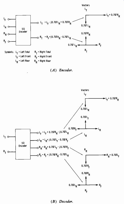
Fig. 7-7. The basic SQ matrix system.
The SQ Matrix System
The basic SQ matrix system employed by Columbia Records for cutting quad discs is shown in Fig. 7-7. Fig. 7-7A represents the encoding matrix which supplies the required phase shift within two degrees over the audio band of 20 to 20,000 Hz. The-j and +j terms in the matrix equations signify how the signal components to the two rear channels are shifted in phase by opposite angles of 90° to result in a 180° phase relationship.
Fig. 7-7B shows the basic decoder matrix, which is complementary to the encoder matrix of Fig. 7-7A.
1P. Scheiber, "Four Channels and Compatibility," Journal of the Audio Engineering Society, April 1971.
The separation between left and right front speakers and left and right rear speakers is approximately as good as ordinary stereo disc separation.
However, it may be observed from the matrix equations and the vector diagrams of Fig. 7-7 that some crossover of information occurs between the front and rear channels. With the conventional (basic) decoder matrix of Fig. 7-7B, the front-back separation is only about 3 dB. A special matrix blend decoder has been developed which trades off some of the separation in the left-right channels (both front and rear) to gain better front-back separation. Columbia Records says that many variations of cross-coupling ratios are practical using the same type of passive circuitry. Their most efficient blend decoder (in terms of front-back channel separation) at the time of this writing has the following specified characteristics:
Left-front-right-front channel separation: 14 dB Left-front-right-rear channel separation: 8 dB Center-front-center rear separation: 7 dB Either the basic matrix or the blend matrix decoder operates with passive circuitry composed of fixed phase-shift and combining networks. In contrast, the SQ Logic Decoder is an active device employed in conjunction with a basic matrix circuit. Input logic circuitry monitors the incoming signals before they reach the matrix network but does not otherwise affect the decoding matrix. This matrix feeds the four individual channel amplifiers which, in the Logic system, are voltage-controlled variable-gain devices. Analysis of the various amplitude and phase relationships of the input signals by the logic network results in a derivation of certain command functions such that appropriate individual control voltages are fed to each of the variable-gain amplifiers. The automatic gain variation in each amplifier changes dynamically as a function of the disc modulation.
The manufacturers claim this technique makes it possible to isolate a signal in any channel with an arbitrary or selectable degree of cross talk to the other channels.
A factor in the SQ system which critics of the entire matrixed technique consider a drawback is the lack of a "rear center" channel, as illustrated in Fig. 7-8. This shows the vector sum for a sound source in the center of the rear area that would produce equal signal amplitudes in LR and RR when LF and RF theoretically receive no signal. In this case, the output of the encoder is essentially zero. Obviously, this cancellation depends on many variables such as frequency, phase differences, and precision of levels reaching the two rear-channel pickups. Critics of the SQ system, including some matrix manufacturers, claim that this equal-energy distribution often occurs in mix-down of multiple-channel tape recordings into two or four tracks, and that lack of directionality and loss of sound localization results. It is known that CBS instructs the recording engineers to avoid placing soloists or any important bit of information in the rear center of the pickup area.
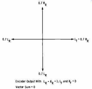
Fig. 7-8. Lack of "rear center" channel.
Another interesting situation exists when all channels receive identical signals. The resultant encoder output is depicted in Fig. 7-9, which shows that most of the sound energy would be concentrated in the left front channel.
RIAJ Standards on Matrix System Disc Recording
Before proceeding with a discussion of the QS system, it will be helpful to present extracts from "Standard of the Engineering Committee, RIAJ (Record Industry Association of Japan) on Regular Matrix System Disc Recording." These extracts follow.
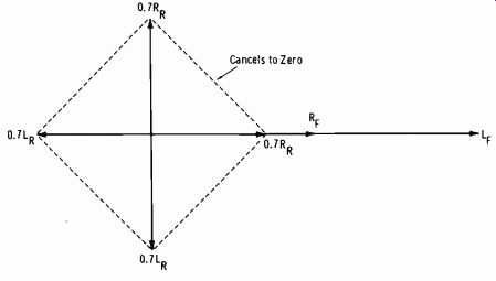
Fig. 7-9. Encoder output when LF = RF = LR = RTt.
1. SCOPE OF APPLICABILITY
This standard shall apply to commercially marketed regular matrix system disc recordings. JIS regulations set forth under S. 8502 (Disc Recording) shall apply to all aspects of such recordings not covered by this standard.
2. RECORDING SYSTEM
The sound groove of the regular matrix system disc recording shall be modulated by two signals, left and right, in two directions at 90° to each other and at 45° to the record surface. These two signals shall be converted from multiple original signals in accordance with the regulations given under subsection 2.1. The left signal shall be recorded in the wall of the groove which is closer to the center axis of the record, and the right signal in the opposite wall.
If the two signals are in phase with each other and identical in quantity, they shall be recorded in such a manner that they can be reproduced by the movement of a reproducing stylus tip in directions parallel to the record surface and lateral to the sound groove.
2.1. Conversion of Signals
The two signals that modulate the sound groove shall consist of one left signal and one right signal converted from multiple original signals. The conversion of original signals into these two signals shall basically be achieved in the manner described below.
2.1.1. Front and Back Signals
A signal originated at the front center shall be converted into a left signal and a right signal which are mutually in phase and of identical quantity.
A signal originated at the back center shall be converted into a left signal and a right signal which are out of phase with each other by 180° but of identical quantity.
2.1.2. Left and Right Signals
A signal originated on the left-hand (right-hand) side of the front and back centers shall be converted so that the left (right) signal is of greater quantity than the right (left) signal.
2.1.3. Center Signal
A signal originated at the center of the original sound field shall be converted so that the left and right signals are of identical quantity but so that the former has a phase lead of 90° relative to the latter.
2.2. Relationship of Direction of Sound Groove Modulation to Sound Source Direction
The relationship of the direction of the modulation of the sound groove to the direction of the corresponding sound source in the original sound field shall, in principle, be such that the angular direction of the former is half the angular direction of the latter (Fig. 7-10) .
(A) Direction of sound (B) Direction of sound groove source (S) . modulation (S') .
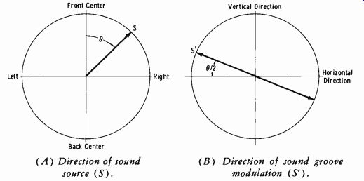
Fig. 7-10. Directions of sound source and sound groove modulation.
ELABORATION
FOREWORD
The Engineering Committee of the Record Industry Association of Japan has compared and examined the various matrix system disc recordings being marketed by various manufacturers to date. Results of such studies have ascertained that all of them, with the exception of the SQ matrix system, are based fundamentally on one and the same system, that they are encoded similarly, and that they possess satisfactory compatibility with one another. Hence the same committee hereby standardizes them as "regular matrix system disc recordings." NOTE: At the time of this writing, Electro-Voice is providing a modification to its own decoder for use with the CBS-Sony SQ matrix system.
1. SCOPE AND APPLICABILITY
This standard governs only those aspects which are peculiar to the regular matrix system disc recording. All other aspects, such as its physical dimensions and quality, shall be regulated by JIS. S. 8502 (Disc Recording).
The regular matrix system disc recording which this standard regulates encompasses all matrix system disc recordings that are cut by converting the information of sound source directions into linear modulations of a spiral sound groove.
2. RECORDING SYSTEM
So as to ensure compatibility with two-channel stereo playback, this standard is formulated in compliance with the stereophonic recording system stipulated under JIS. S. 8502.
Note: As the sound source moves closer to the center á the sound field, the locus approaches an ellipse.
When it is at the dead center, the locus assumes a perfect circle.
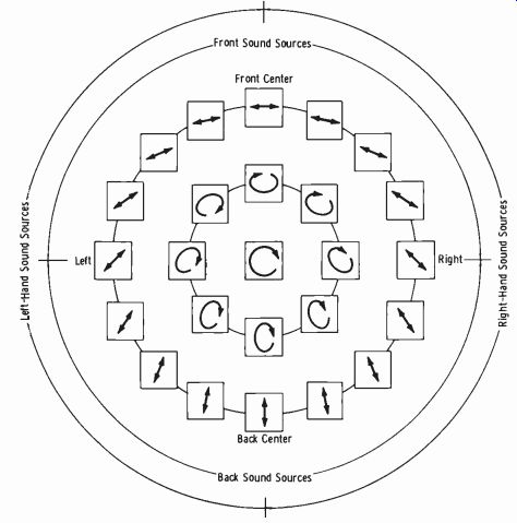
Fig. 7-11. Direction of sound groove modulation.
Thus the regular matrix system disc recording manufactured to this standard, when and if reproduced by regular two-channel stereo playback equipment, does not impair the relative sound image and sound volume balance between the left and right channels.
3. RELATIONSHIP OF DIRECTION OF SOUND GROOVE MODULATION TO SOUND SOURCE DIRECTION
The relationship of the direction of a sound source in the original sound field to the direction of the modulation of the sound groove on the regular matrix system disc recording is set forth in Fig. 7-11.
The term "direction of a sound source in the original sound field" is used to describe the direction of a sound source intended at the time of recording, whereas the term "direction of the modulation of the sound groove" is used to describe the locus of the vibration of a cutting stylus tip.
To reproduce the regular matrix system disc recording in more than two channels, it is thus possible to place three or more loudspeakers freely, depending upon the matrixing parameter of the decoder used (including a speaker matrix type) .
Basic Principles of QS Encoding-Decoding System
The ability to encode the original 360° without any loss and mis-localization of sound sources was achieved by the adaptation of-±90° phase shifters and by setting disc-cutting vector angles (0) between four channels at 22.5° in an ordinary disc groove. Fig. 7-12 presents a basic block diagram of the Sansui QS system.
Unlike conventional four-channel matrixing circuitry, this encoder phase-shifts the left and right rear channels ±90° instead of using an ordinary 180° phase inverting method to achieve a reverse phase relation ship between these channels. This puts the four encoded channels in an ideal phase relationship, as shown in Fig. 7-13A. Signals are not cancelled in the encoder, and any information from any direction in the original sound field can be encoded.
The above-mentioned phase-shift technique allows a unique action at the decoder. The rear channels are phase shifted in a manner opposite to that in the encoder; namely, the left rear is shifted by-90° and right rear by +90°. Thus the reverse-phase relationship between the rear channels is reconverted to an in-phase one, as depicted by Fig. 7-13B.
The function can be explained in terms of vector angles in the disc groove. The encoder outputs will be:
L= (LF+jLR) cos0+ (RF+ jRR) sin0
R = (RF- jRR) cos 0+ (LF- jLR) sin 0
The above equations show that there is no loss of information in the en coding process by adapting j-phase (±90°) shifters in the manner used here.
Now assume a signal of amplitude 1 enters all channels simultaneously in this system:
L= (cos 0+ sin 0) + j (cos 0 + sin0) = 1.30+j1.30 R= (cos 0+sin())- j (cos 0 + sin0) = 1.30-j1.30
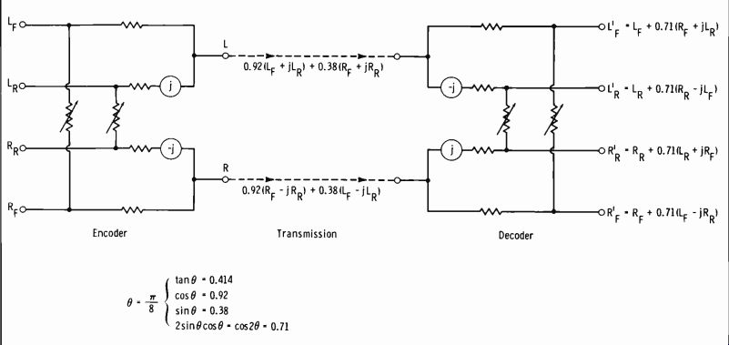
Fig. 7-12.
(A) Encoder output. (B) Decoder output.
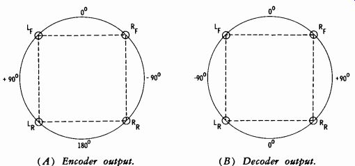
Fig. 7-13. Phase relationship between channels.
Thus the encoded output signals of LT and RT are identical in level but have a phase difference of 90°. After decoding, identical levels exist in all channels, with the two rear channels phase shifted by j.
Next assume a signal of amplitude 1 enters LR and RR, with zero signal in LF and RF:
L=j (cos 6+ sin e) = j1.30
R=-j(cos0+ sin e) _-j1.30
Thus the encoded outputs in this instance are signals 180° out of phase.
When reconverted in the decoder, they are equal in-phase signals, localizing the sound at rear center.
Blending Coefficient for the Encoder-Decoder
In determining the value of the interchannel blending coefficient ( for a matrix encoder), careful consideration must be given to the types of pro gram sources available. Even conventional two-channel stereo sources are available in variety, including:
1. Those utilizing only two (left and right) monophonic channels in dependently (no intermediate phantoms).
2. Those with sound images localized at three monophonic channels, i.e., left, center, and right.
3. Multiple-track sources with sound images localized at multiple points on a line between left and right channels.
4. Sound-field recordings without any distinctive sound images, such as those of a church organ.
Four-channel program sources can also be classified in a similar manner, and this fact must be carefully weighed in determining the blending coefficient. The blending quantity among four channels of information in the encoding process must in no way restrict the flexibility.
In a four-channel stereo system, the information contained in each channel must be treated equally. This can be accomplished only when the vector angles among the four channels are identical, i.e., when they are all Tr/8 (20 = r/4). In this condition:
A. The cross talks among adjacent channels are equally 3 dB. Thus, the four channels are reproduced uniformly to obtain a square sound field (Fig. 7-14).
B. Equal volume balance is attained among the four channels, so that distinct sound images can be positioned in any direction inside the square sound field (Fig. 7-15 ).
C. The encoder and decoder can be allowed to blend an identical quantity of information into adjacent channels.
D. Programs encoded by an encoder in which 0 = 22.5° can be decoded by a decoder with a different vector angular value without losing much of their four-channel effect.
E. Conversely, a decoder in which 0 = 22.5° is able to reproduce programs encoded by an encoder with a different vector angular value without losing much of their four-channel effect.
To clarify the points made above, Figs. 7-15, 7-16A, and 7-16B show the sound pressure response in different channels to visualize how the sound images are formulated in reproduction. Fig. 7-15 illustrates eight visual patterns of the phase, cross-talk, and directional relationships among the channels. It is noted that the QS decoder allows distinct psychoacoustic images of direction to be formed in the same directions as those in the original sound field.
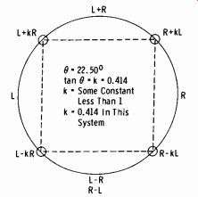
Fig. 7-14. Ideal four-channel reproduction of sound field.
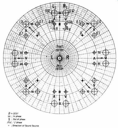
Fig. 7-15. Sound pressure response patterns and phase relationships among
channels in reproduced sound field.
(A) Left front input.
(B) Front center input.
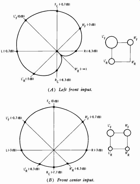
Fig. 7-16. Sound pressure response patterns.
Fig. 7-16A shows the sound pressure response of a sound source located in the left front channel and indicates the reproduced sound image is shaped as a symmetrical pattern accurately directed from the crossing of polar coordinates toward the point where the sound source is located. Fig. 7-16B shows the same situation with respect to a sound source located at the front center. While all four speaker systems emit sound in this case, the cross talk to the opposite center direction is -7.7 dB, enabling a distinctively well balanced psychoacoustic field to be created among the four channels with the accurate directionality toward the front center.
Let us now consider what would happen if vector angle O were not 22.5°. First, if it were smaller than 22.5° (Fig. 7-17A) , the separation between the left front and rear and between the right front and rear would be impaired. This would result in a vertically short oblong sound field, making it impossible to obtain equal separations among the four channels.
If the angle were larger than 22.5° (Fig. 7-17B) , the separation between the left and right front and between the left and right rear would deteriorate, impairing the volume balance among the channels.
Thus it can be seen that the value of vector angle O has a serious effect on the directional characteristics of the reproduced sound images and the shape of the reproduced sound field. This is relatively inconsequential in a 2-2-4 conversion, but if the vector angle were different in the encoder and decoder, it is obvious that the original sound field pattern would not be faithfully reproduced.
(A) Angle less than 22.5° . (B) Angle greater than 22.5°.
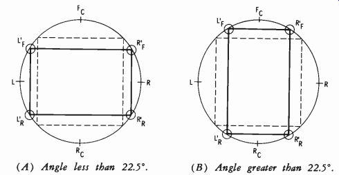
Fig. 7-17. Reproduced sound field simulation when angle theta is not 22.5°.
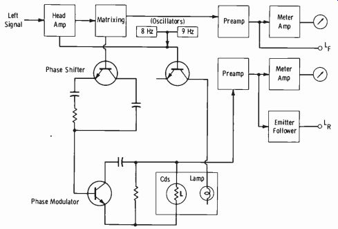
Fig. 7-18 Phase modulator circuit.
Phase Modulation
In a live (original) sound field, the indirect sound components converge upon the human ear from innumerable directions and with infinitely varying phase differences. Such a sound field, therefore, cannot be reproduced faithfully simply by adding one or two more speaker systems, although this will make possible a considerable improvement in the tonal quality over conventional two-channel stereo. Furthermore, the sound sources (direct sounds) themselves keep changing their positions and strengths every moment, so that the relative relationship between the direct and indirect becomes To reproduce the original sound field faithfully, it is therefore necessary to reproduce the direct and indirect sound components with continuously varying phases.
The Sansui QS 4-channel synthesizer decoder adopts a phase modulator circuit (Fig. 7-18) for this purpose. This circuit "phase modulates" the rear-channel signals, which then meet with the non-modulated direct sound components from the front speaker systems in the air to enhance the presence of the reproduced sound. Phase modulation in this case produces infinitesimal time and frequency differences between the indirect sound components and the non-modulated direct sound components. Not only is the presence of the reproduced sound greatly improved by this process, but the dynamic range of "pulsive" notes is substantially expanded. In designing the system, Sansui engineers repeated actual listening tests for a long period of time to determine the optimum frequency range and depth of phase modulation.
While various circuit designs are possible for such a phase modulator circuit, the Sansui QS 4-channel synthesizer decoder adopts a phase-shift frequency modulation system, whereby the resistance component is altered in circuits similar to the phase-shifter circuit. Modulating signals are a mixture of the middle- and high-frequency components of the audio input signal and the signals from an oscillator constructed of two generators, permitting the left and right channels to be modulated by different signals.
If a sine wave is applied (for the purpose of testing, etc.) , the resultant phase modulation would acquire a periodic nature. But in the case of an ordinary music source, the modulating signals are random signals for an optimum phase-modulation effect.
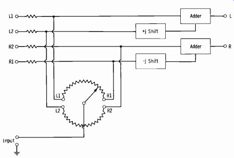
Fig. 7-19. Panning circuit.
Panning Technique The blending coefficient can be varied electrically by the use of panpots on the mixing console, as illustrated by Fig. 7-19. The two pairs of encoder inputs (L1 and R1, and L2 and R2) are each independently manipulated.
By this technique it is possible to shift the focus in any direction at the recording end; speaker systems can be positioned anywhere on the playback side. Thus this coding system permits the localization of sound images at any point in a full 360° both in recording and playback, not only in a four-channel setup but in any other multichannel setup.
7-6. THE DISCRETE FOUR-CHANNEL SYSTEM
The discrete system, as implied by the term, involves the transmission of information in four separate channels throughout the system. Proponents of this method take exception to the "psychoacoustic" matrix system, claiming that true quad sound cannot be a compromise from four distinct channels representing left and right front and left and right rear. The discrete system therefore requires some form of carrier multiplexing of a stereo fm transmitter to carry the two additional channels of information.
We will first study the discrete system in its initial closed-circuit form, starting with the quad disc and ending with the four separate speaker systems. We will then describe briefly the currently proposed techniques of broadcasting discrete quad sound through a modified fm stereo transmitter.
The RCA-Panasonic-JVC discrete system, currently termed the CD-4 system, will be described, since this is the most popular at the time of guide preparation. The term CD-4 is derived from Compatible Discrete 4-Channel, and this designation may or may not be retained by RCA for future production models.
Signal relationships of the four channels are as follows:
Channel 1: Left front
Channel 2: Left rear
Channel 3: Right front
Channel 4: Right rear
Matrixing is employed in the discrete system, but the function is different than that of the matrix system previously described. The recording matrix circuit accepts the four discrete signal sources and produces four discrete signal outputs as follows:
Channel 1 plus Channel 2. (LF + LR Channel 3 plus Channel 4. (RF + RR ) Channel 1 minus Channel 2. (LF- LR ) Channel 3 minus Channel 4. (RF- RR )
SUM CHANNELS DIFFERENCE CHANNELS
Very briefly, the subtracted channels frequency and phase modulate a 30-kHz carrier which is then mixed with the sum channels. This mixed signal is fed to a recording amplifier which drives a specially designed cut ting head for the quad disc. The quad disc actually contains the modulated carrier and its sidebands with a frequency response up to 45 kHz.
The CD-4 Recording System
Fig. 7-20A shows a basic block diagram of the method of recording a CD-4 disc. The sum of channel 1 plus channel 2 (LF + LA) is recorded in the left wall of the groove (Fig. 7-20B) , and the sum of channel 3 and channel 4 (RF + RR) is recorded in the right wall. The difference signals frequency and phase modulate a 30-kHz carrier which is also recorded on the disc, in the manner illustrated by Fig. 7-20B.
(A) Block diagram.
(B) Groove modulation.
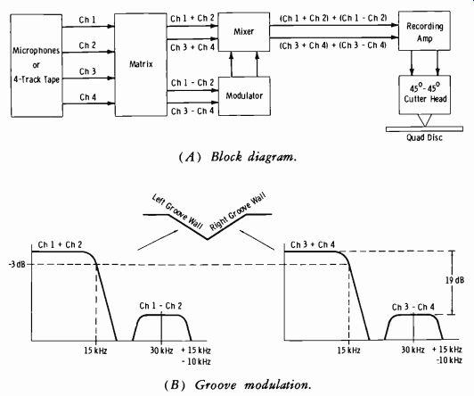
Fig. 7-20. CD-4 disc recording system.
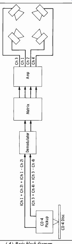
Fig. 7-21.
The CD-4 Reproducing System
Fig. 7-21A is a basic block diagram of the reproducing system. The pickup cartridge is a special high-compliance type with a stylus pressure of about 1.5 grams and a frequency response of 20 Hz to 45 kHz. Fig. 7-21B shows details of the demodulator block in Fig. 7-21A. The front-to-rear separation for this system is said to be about 25 dB, or very nearly equal to conventional stereo left-right separation.
When the CD-4 disc is played on a conventional stereo system, the stereo pickup is not sensitive to the 30-kHz carrier, and the sum signals are re produced in the two channels as for normal stereo recordings. When the quad disc is played monophonically, the sum of all four signals is reproduced. For either stereo or monophonic reproduction, the demodulator is switched out of the circuit.
Getting Discrete Quad on the Air
As mentioned previously, the broadcasting of discrete four-channel sound sources involves some form of carrier multiplexing technique which requires special FCC approval. At the time of this writing, only experimental broadcasting has been authorized, with no approval of any specific discrete system.
Fig. 7-22 shows the multiplexed carrier frequencies of three proposed discrete quad systems. McMartin's TDM ( time-division-multiplex) system places the subcarrier at the presently assigned SCA frequency of 67 kHz.
The space is time-shared by sampling at the rate of 19 kHz locked to the stereo pilot frequency. The total bandwidth of 16 kHz provides 8 kHz for the left-rear and right-rear channels. Amplitude modulation is used in this time-shared system.
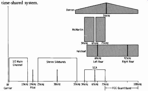
Fig. 7-22. Three proposed carrier multiplexing systems.
The Halstead system also provides 8-kHz channels for the left-rear and right-rear speakers. The left-rear subcarrier is at 69 kHz, and the right-rear subcarrier is at 92 kHz. Thus the upper sidebands of the 92-kHz subcarrier extend to the limit of the assigned guard band at 100 kHz. However, the fm subcarriers are at low level and produce only first-order sidebands, and the stereo modulation is reduced below the maximum deviation.
Proponents of the system claim that tests with a panoramic spectrum analyzer reveal that signals produced by this technique extend no further at the limit extreme than do modulation products of the conventional stereo transmitter using 100-percent modulation. The degradation in signal-to-noise ratio is approximately 1.5 dB for each 10-percent reduction of modulation in an fm system.
The Dorren system employs a 76-kHz subcarrier which supplies decoding information to direct the four discrete channels to their proper speakers. Full 50-15,000 Hz range for all speakers is claimed for this technique, with channel separation of 40 to 42 dB over this range. The signal-to-noise ratio is said to be 60 to 62 dB per channel. Very little information has been released at the time of this writing, probably due to patent processing.
7-7. TRANSMITTER REMOTE-CONTROL FACILITIES
It is becoming almost standard practice to operate the transmitter remotely from the studio control room. The control units are normally inter connected by telephone lines, although microwave links have been used.
Transmitter on-off, power adjustment, directional operation, and various monitoring circuits are provided.
(A) Studio unit. (B) Transmitter unit. Courtesy Schafer Electronics Corp.
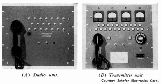
Fig. 7-23. Remote control system panels.
The control panel of a typical remote-control system is shown in Fig. 7-23. The transmitter control unit contains the calibration controls. These are adjusted so that the remote meter readings at the studio (frequency, modulation, etc.) are the same as those at the transmitter. Built-in tele phone communication eliminates the need for an extra phone line. This is an all-dc system which uses no vacuum tubes and operates on any two ordinary metallic telephone circuits. There are 24 metering circuits and 40 control circuits included in this particular studio control unit. The tele phone-type dial operates pulsing relays which connect the monitoring point desired.
The following controls are required:
Transmitter start on–off
Tower lights on–off
Final-stage tuning
Output-power control
The following metering circuits are normally provided:
Deviation of carrier from assigned frequency
Modulation percentage
Final-stage plate voltage
Final-stage plate current
Antenna current or currents
Antenna-current phase (for directional antennas)
Additional controls and metering points may be added.
Two telephone circuits are required, one for the control line from the studio to the transmitter and one for the metering-line return from the transmitter to the studio. A diagram of the RCA remote-control system operation is shown in Fig. 7-24. A description of this system follows.
When switch S is closed on the control unit, power supply A through voltage divider B and telephone dial C normally supplies 12 volts dc to the control line. Operation of the lower switch in unit B increases this voltage to 35 volts, and operation of the raise switch in unit B increases this voltage to 100 volts. Telephone dial C interrupts the line voltage with a number of impulses corresponding to the number dialed. Stepping system D with its power supply E controls the indicating lights showing the number dialed.
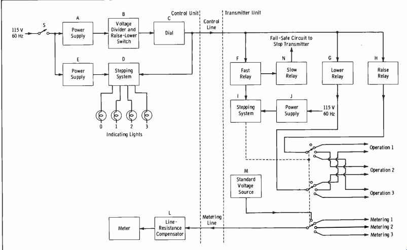
Fig. 7-24.
In the transmitter unit, relays F, G, and H are bridged across the control line. Relay F is energized when switch S is closed and follows the dial impulses. Relay F operates slow relay N which does not release during dial impulses. Relay N controls the transmitter power so that in the event the control-line voltage fails, the transmitter is taken off the air.
Relay G operates when the lower switch is operated, and relays G and H both are operated when the raise switch is operated. Relay F operates step ping system I, which controls the indicating lights showing the number dialed and also connects the raise and lower relays to any one of ten external operating units consisting of reversible motors or control relays.
Stepping system I also connects the metering line to any one of nine external metering elements which convert any desired ac or dc potential or current being measured to a value suitable for remote measurement.
The entire metering system is calibrated against a standard source of voltage on position 0. This accurately compensates for any variation in the line resistance with temperature changes.
A metering circuit is required from the control unit at the remote-control point to the transmitter unit. This circuit is to be a low-grade tele phone pair with a maximum total dc loop resistance of 4000 ohms. This circuit must furnish a dc path, and no simplex or grounds of any type are permissible.
Maximum voltage line-to-line: 0.5 volt Maximum current through circuit: 200 microamperes Line termination protection: 200-mA fuses and Thyrite protectors to ground Maximum voltage line-to-ground: 100 volts Maximum current with line shorted: Approx 10 mA A control circuit is required from the control unit at the remote control point to the transmitter unit. This circuit is to be a low-grade telephone circuit with a total dc loop resistance of 4000 ohms maximum. This circuit must furnish a dc path, and no simplex or grounds of any type are recommended. The circuit carries only pulsed dc (10 pulses per second).
Maximum voltage line-to-line: 100 volts
Maximum current through circuits: 15 mA
(A) Circuit for control of quantities such as plate tuning or antenna loading. (B) Details of latching-relay circuit.
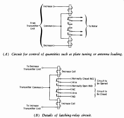
Fig. 7-25. Typical remote-control circuits.
Line termination protection: 250-mA fuses
Maximum current with line shorted: 82 mA
The transmitter unit provides the required number of calibrating potentiometers so that the remote meters at the studio read the same as those at the transmitter. Fig. 7-25 illustrates typical transmitter remote-control circuitry. Fig. 7-26 shows typical remote-metering circuitry. Table 7-1 shows typical AM station dial functions.
The maintenance procedures for components of a remote-control system such as resistors, capacitors, relays, etc., are covered in other Sections.
Procedures for the system as a working entity may be outlined as follows:
1. Always check and record the dc resistance of the telephone pairs employed. This serves as a reference for future use.
2. Check the dc resistance of the telephone pair to ground with a sensitive vtvm and record it for future reference.
3. Periodically, or whenever conditions warrant, run a noise-level measurement on the line. Electrical storms or other conditions along the pair routing may produce a low-resistance ground or cross talk, which can result in erratic operation of the remote-control or metering circuits.
4. Check and calibrate all metering circuits at least as often as required by current FCC regulations or special conditions that may be contained in the station remote-control authorization.
NOTE: A transmitter remote control involving microwave and telemetry is described in Section 8-6.
(A) Line-voltage metering. (B) Tower-light current metering.
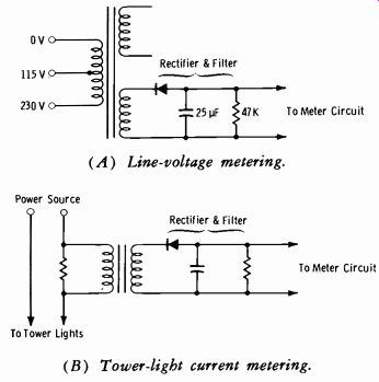
Fig. 7-26. Typical remote-metering circuits.

Table 7-1. Control-Unit Dial Functions
7-8. AUTOMATION SYSTEMS
Automation in am-fm broadcasting is here to stay, and to grow. A basic block diagram of automation as applied to technical operations is shown in Fig. 7-27. The type and extent of program control varies considerably as evident in following descriptions, but the overall function is similar to that illustrated.
The CCA Mini-Automation System
Fig. 7-28 shows four lever switches, each with a four-position capacity.
The event at which each program source occurs can quickly be arranged by setting the four switches to the desired positions. Normally, the cue detectors associated with the tape machines advance the system from one pre arranged program source to another. However, upon request, the built-in priority clock can be used to interrupt the sequence. Located above each of the switches is a status light which, when registered, indicates that this event is next in the sequence.
An inexpensive but reliable one-hour clock is provided. It has facilities for presetting two switches in one-minute increments. Each of these switches is normally supplied prewired to the first two audio sources, which can thus be used on a real-time priority basis rather than on a sequential basis. For example, one source could be a combination of station identification, time announce, and prerecorded news which would occur every half hour. The second source could be one or several multiple cartridge machines which could be set up to play every 10 minutes. Please note that the system will not normally interrupt its programming and switch to another source in the middle of a message. The cue detector will normally restore the program line, and if a priority has been called, this source will then supersede the sequential event.
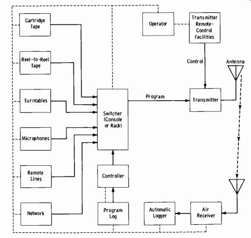
Fig. 7-27. Basic technical automation facility.
The system contains two plug-in 25-Hz cue detectors. These units are designed to detect the presence of a 25-Hz tone at a level as low as-30 dBm and will not overload or cause miscues at levels as high as +10 dBm.
In a normal automation system, the 25-Hz end-of-message tone is generally recorded on the left channel at a level of approximately-5 dBm. The 40 dB dynamic range of the CCA Q-Tectors permits them to function over a wide range of errors in the production and playback of 25-Hz cue information. Each detector has controls for achieving an adjustable overlap.
The unit contains a built-in 25-Hz generator with dual 25-Hz filters.
It is preset to operate for 2 seconds and can be controlled from either the front panel or a remote position. It is independent from the normal pro gram lines, and thus production work can be done while the system is providing programs.
The system also contains solid-state circuitry which can sense the absence of signal on the program line. This circuitry can be adjusted to operate after any predetermined period of silence from 2 to 20 seconds. Thus, if one of the machines should become inoperative, the silence sensor will detect the problem and sequence the system to the next scheduled event.
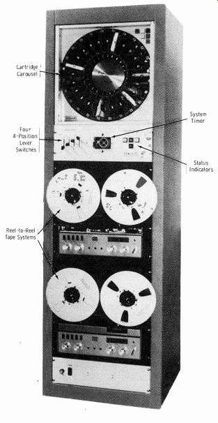
Fig. 7-28. CCA Mini-Automation system.
The unit contains a front-panel switch which when depressed serves as a priority. Thus, once this button is operated, the next source of the automation system would be that associated with the remote. The system may then be used to serve as a program source, and periodically news or some other priority may be inserted in the system. The silence sensor is disabled during use of the remote source to allow flexibility of program con tent.
A series of panels can be used in conjunction with the CCA automation systems to expand a single channel from one to three more audio sources.
The simplest version of the family of expansion panels is the Model EC3-C.
It is designed to expand single-play tape cartridge machines or multiple-cartridge machines such as the Carousel. The additional three sources and the original source of the audio channel can be controlled from the front panel of the EC3-C. Each sub-source has a switch associated with it. This switch programs the source or bypasses the sub-source. There is also a pro vision for an external override, which when set to override the system will skip all remaining sub-sources to be played and will restore operation to the basic automation system at the end of the selection being played. This permits priority override of the expansion system.
On the rear of each panel which contains a Q-Tector are controls for adjusting the time after the end of the cue tone at which the reel-to-reel tape machine will stop. This adjustable delay permits achieving a very tight format as well as any practical overlay. A switch for each internal cue detector is available on the rear for overriding any preset overlay.
The CAA RA-50-1 (random access unit) is designed to permit rapid, reliable control on a random basis of the 24 cartridges stored in the Carousel multiple-cartridge playback machine. This panel permits the broad caster rapidly to arrange the sequence in which the various cartridges will play without the necessity of removing the cartridges from their positions within the Carousel.
The random-access unit contains 50 levers, each of which refers to an individual event. Placing these levers in any one of 24 positions determines the cartridge which will operate when that event is sequentially selected.
Each lever also has a skip position which, in the CCA automated system, will bypass to the next cartridge source. A front panel light indicates the next event to be played in the Carousel. To the right of the panel are three switches which provide for advancing the events rapidly, converting to a consecutive mode of operation of the system, and resetting the programming to event No. 1.
The RCA Basic Automation System
(A) System I. (B) System V.
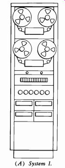
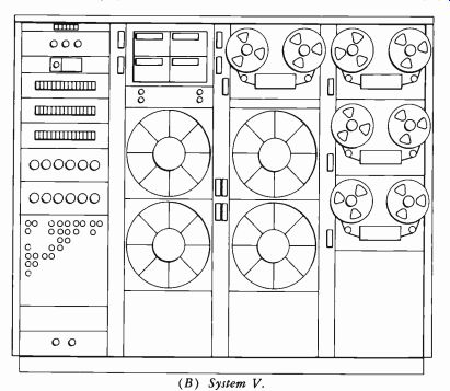
Fig. 7-29. RCA radio automation systems.
The RCA automation systems for radio cover a broad range of applications as fundamentally illustrated in Fig. 7-29. The System I shown in Fig. 7-29A consists of two reel playbacks, the programmer, a one-hour timer, and two cartridge units. For a simple program pattern, the operator could program four or five hours. The one-hour timer is a cycling device so that the same sequence of events can be set up to happen as many times as required. System V (Fig. 7-29B) provides 24-hour programming with complex patterns. Systems II, III, and IV are in between these extremes so that individual tailoring of a system to specific requirements can be accomplished.
Many automation systems use some form of memory storage-paper tape, magnetic tape, punched cards, coded log, or other-which is programmed in advance for a certain sequence of events resulting in the automatic control of tape machines, turntables, and other program sources.
There are advantages to memory storage, but as the complexity of the sequence of events increases, it sometimes becomes very rigid and difficult to change.
In the simplest concept, one program event starts the next, so a memory is not needed. What can be used instead is a method of routing events that permits quick and easy change of the program format, event, or sequences at any time. Live and automated operations are readily integrated. Uncertainty can be eliminated by continuous program status indication to the operator, who may be a nontechnical person with very little training. This is the operation of RCA's basic automation system. It borrows solid-state computer techniques to permit flexibility of programming with simple setup requirements.
A major unit of RCA automation is the BCA-15B programmer (Fig. 7-30). It is designed to switch between as many as 18 preselected audio sources, such as reel and cartridge tape machines, turntables, and micro phones, and continue to sequence them automatically in any preset pattern of events as long as required.
The sequence of events is programmed by means of thumbwheel switches (Fig. 7-31) , which select events from any of the up to 18 pro gram sources. Control is given in sequence by circuits in the unit, the end of one event (in the smallest systems) initiating the beginning of the next.
The event being played is shown by a tally light above the switch. The capacity is 15 events. Modifications to the program may be made at any time either by (A) resetting the thumbwheel switches, (B) starting an event using the front-panel push buttons, or (C) manually starting the audio source itself.
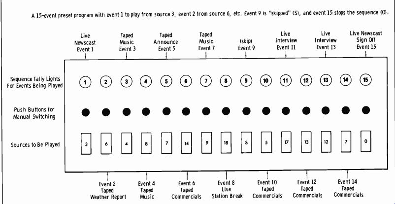
Fig. 7-30
Both A and B continue to repeat a 5-source sequence, but 20-position recycling switch in B uses only six thumbwheel positions.
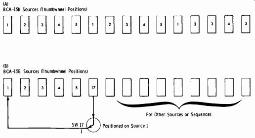
Fig. 7-31. Use of thumbwheel switches for automation programming.
Programmers may be cascaded to provide 30, 45, 60, or more events. Or, a second unit may be used to provide a subsequence to the first BCA-15 programmer, further expanding the programming capability of the combination. The recycling function increases the capability by repeating frequency, used program segments. By use of cycling and sub-sequencing techniques, anywhere from a few hours to a full day's programming may be set up on two BCA-15B programmers.
Another major unit of the automation system is the program clock.
This is actually a timer which synchronizes the program on an average time basis. The timer does not chop or fade program material; rather, for smoothest operation, it adds or deletes events from programmed musical fill at the end of a time segment to guarantee station identification within legal rime limits. It then starts a new event after the ID segment is completed. The clock does not work on real time, but rather pre-arms the system so that the station break occurs in accordance with FCC requirements.
A typical clock function is shown by Fig. 7-32. For simplicity, each of sequences A, B, and C is repeated using identical sources. Starting on the hour, sources 1 to 9 ( sequences A and B) play in consecutive order. After sequence B finishes, source 17 returns the program to source 6, through the program clock timers, and sequence B plays again. Sequence B will repeat until 15 minutes have elapsed; then the quarter-hour timer routes the pro gram to source 11 in sequence C. By the time sequence C is finished playing, the quarter-hour timer will have returned to source 6. Sequence B will continue to repeat until 30 minutes have elapsed and the half-hour timer changes position. This routes the program back to sequence A, and the A-B-C-B cycle that occurred during the first half hour repeats in the second half hour under control of the three-quarter and one-hour timers.
For stations requiring rigid timing, as when joining and separating from network lines, the station break can be clocked precisely. Here the equipment, activated by network signaling tones or a digital clock, fades the local programming at the precise time and restarts the automation system at the finish of the network activity.
The event being played and the next to play are read out continuously on the faces of the BCA-15 programmer, the clock timer, and the status indicators on each source. Thus the portion of the program in play and the entire program sequence are always visible to the operator for reference or change.
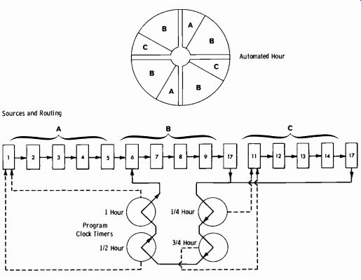
Fig. 7-32. Use of clock timers for breaks at quarter-hour intervals. Sources
and Routing. Automated Hour.
Even further identification is available in an accessory known as the source status readout system. This is a three-function illuminated display showing the status ("play," "next," and "pass") of each audio source, and it incorporates a pass switch to remove a source from the system for service, loading, cueing, or recording use. The play light shows that the source is operating on-air. When the pass indicator is lighted, the source is not avail able for use and is automatically skipped when called up by the program mer. The skip is achieved with no dropout or pause of the audio, just as it would be for a blown fuse, slack tape, or improperly seated cartridge. The pass light goes out when the source is properly loaded and ready to play.
If it does not do so, the operator is immediately warned of a malfunction.
The next indicator shows the next source programmed to play, and if the source is to be skipped automatically, the actual next source to play is indicated.
The studio override and manual control system allows a live microphone or other console-controlled source to be inserted into the automation programming sequence with considerable ease. These three insertion modes are provided:
1. The live source can be programmed into the BCA-15 programmer in the normal manner by dialing up the assigned source number. When this point in programming approaches, the operator will receive a "next" indication to which he must reply with a "ready" signal to indicate his presence in the studio. He then is supplied an "on-air" indication to start. At the end of the live segment, the operator presses a "pass" switch which returns control to the programmer. If it should happen that the studio is not manned when programmed, an automatic skip will occur, and the programmer will select the next event.
2. The announcer can interrupt the automation sequence and go live at tie end of the on-air event by operating a "next" switch in a control center located at the console or announcer's booth. At the conclusion of a live insert, the program will automatically continue from the point of interruption.
3. The announcer can instantaneously override the on-air automation program and interrupt the program sequence for news flashes, etc., by operation of a play control. The program will automatically continue from the start of the next programmed event at the end of the interruption.
An additional operator aid is the automatic cue accessory. With this, any audio source placed in pass status will automatically feed its audio into an audition bus monitored by a cue amplifier-speaker unit. This system allows audio sources to be cued up, or played off line, while the automation system is on the air. For stereo, a lever switch allows selection of channel A, B, or A and B.
The RCA automation equipment is fail-safe in that no source malfunction will shut down the entire system, and most failures will be skipped without interruption of audio. Failures such as tape breakage during play or failure of the operator to return the system to programmer control at the end of a live segment will be picked up after a few seconds (adjustable from 2 to 20 seconds) by a silence sensor, and the next event will start.
Of course, the operator can always override the programmer and play the system manually. The sensor is equipped with a balanced input and a bridging mixing network to combine stereo inputs while maintaining channel-to-charnel isolation. A remote alarm may be triggered by the silence sensor.
The Schafer 900 Series Automation Systems An early model of Schafer automation was shown in Fig. 5-1, Section 5.
This has been replaced by the 900-series systems, Models 901, 902, and 903. The Model 902 shown in Fig. 7-33 is the switch memory system.
When this system is to be used with a network, it also needs the time gate unit for joining and leaving network and other auxiliary functions. Each Carousel in the system employs an M-52-C Carousel memory unit. This is a switch matrix device with 52 positions to select the plays for each Carousel. The Model 903 system utilizes an MOS memory and digital techniques.
Programming the system is accomplished by use of the keyboard shown on the table. Each random-select Carousel is addressed directly by the key board. Both systems feature a solid-state digital clock. The 902 clock is synchronized with the power-line frequency. The 903 clock is crystal con trolled and has a battery backup.
Both systems use the Model 901 control panel as the interface. Thus both systems have individual 25-Hz gates, individual time delays on each trans port, with closed-loop control.
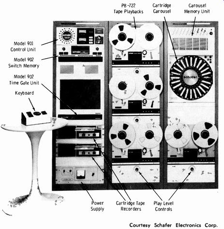
Fig. 7-33. Schafer Model 902 automation system.
The Model 901 control unit is outlined below:
Program Sources Basic
A. Up to 19 audio sources.
B. May be reel-to-reel, cartridge, or cassette.
C. A separate interface card is used for each audio source.
D. One cable assembly from the interface card to each audio source.
E. Solid-state audio switching used throughout.
F. Manual control of each deck is provided.
Reel-to-Reel Interface Card A. Has an active 25-Hz gate.
1. To provide automation advance pulse if deck was on the air.
2. To start adjustable cue delay after 25 Hz leaves.
3. To hold audio on air (if it was on air) until 25 Hz stops.
B. Audio input single ended.
1.-10 dB to +16 input level.
2. 10K to 150 ohms impedance level.
C. 25-Hz lockout.
1. Adjustable delay of 1 to 10 seconds from start of deck.
2. Set at factory for specific deck.
D. Cue Delay.
1. Adjustable delay of 1 to 10 seconds from end of 25 Hz.
2. Adjustable from front by opening front panel.
E. Fade Control.
1. Fade on 0.1 second minimum, 5 seconds maximum.
2. Fade off 0.1 second minimum, 5 seconds maximum.
3. Normal setting 0.5 second on, 2 seconds off.
Cartridge Interface Card A. Accept contact closure from 150-Hz detector in cartridge deck.
1. To provide automation advance pulse if deck was on the air.
2. To hold audio on the air (if it was on the air) until the contacts open.
B. Audio input single ended.
1.-10 dB to +16 dB input level.
2. 10K to 150 ohms impedance level.
C. Contact closure or 150-Hz lockout.
1. Adjustable delay of 1 to 10 seconds from start of deck.
2. Set at factory for specific deck.
D. Fade Control
1. Fade on 0.1 second minimum, 5 seconds maximum.
2. Fade off 0.1 second minimum, 5 seconds maximum.
3. Normal setting 0.5 second on, 2 seconds off.
Cassette Interface Card A. With cassettes having own automation advance and cue sensors, use specifications for cartridge interface card.
B. With cassettes not having separate sensors, use specifications for reel-to-reel interface card.
System Controls & Indicators
A. Start: The Start function causes the audio source selected under Next to be started and played on the air if the system was in a stop condition. If a source is already playing, no action will occur except to cancel a stop request. The start light will come on and stay on as long as a source is on the air.
B. Step Now: The Step Now (sometimes called "panic") function operates only in the run condition by causing the audio source selected under Next to start now and the audio source playing to be removed from the air.
C. Stop: The Stop function places a request for the system to stop running at the end of the present selection. This stop request can be canceled by pressing the start button.
D. Auto Pulse: An auto-pulse lamp gives indication that an automation advance signal was received from the audio source now playing.
E. Closed- Loop Control: The automation advance pulse (auto pulse) generates a start command for the audio source selected to play next.
If for some reason that source is unable to play ( power off to the deck, broken tape, programming error selects non-existing source, etc.) , another auto pulse is generated within 300 milliseconds. This sequence is repeated until a selected source is able to play; this source is then monitored as long as it is on the air.
F. Silence Sense: The line outputs are monitored for continuous presence of signals above-20 dB (adjustable-40 to-10 dB) . Falling below the set point initiates a time delay adjustable from 1 second to 10 seconds; if the time delay is not reset by a return of the audio level above the set point, an auto pulse is generated and advances the system to the next source. Silence sense inhibit capability is provided for studio or network sources.
Audio Monitoring A. Monitor Switch
1. Line
2. Cue
3. Clock Cue
4. Network Cue B. VU Meters
1. Channel A and channel B indication of line output.
2. Channel A and channel B indication of cue output.
C. Stereo Speakers for monitoring line or cue with level control.
D. Mono Check push button to give visual indication of monaural receiver reception level.
Audio Distribution A. Line Output
1. Balanced 600 ohms.
2. Level adjustable from- 10 to +8 dB.
3. 25-Hz filter in each line.
B. Cue Monitor Output
1. Single-ended 10K.
2. Level at 0 dB.
Verified Encoded Logging (Optional)
A. Time-Code Generator
1. Time is sampled from the digital clock and typed out in hour, minute, second, and a.m. or p.m. at the start of an audio source.
Audio source number is typed after the time.
3. Special symbols are typed around the audio device number if an rf monitor contact opens.
B. Clear-Text Log
1. After the time and device number are typed, a clear is read directly from the tape to produce a verified encoded log.
This message does not appear if the rf monitor contacts are open.
EXERCISES
Q7-1. What must be checked when a new and different type of microphone is employed in a stereo application?
Q7-2. Quad sound adds what information to conventional two-channel stereo?
Q7-3. Is an encoder required at the studio for matrixed quad sound?
Q7-4. What is the basic action of an encoder for quad sound?
Q7-5. What does "front center" mean in stereo or quad sound?
Q7-6. May a transmitter be operated by remote control without FCC authorization?
Q7-7. Can studio automation be used without FCC authorization?
Q7-8. Can matrixed quad sound be broadcast without FCC authorization?
Q7-9. Can discrete quad sound be broadcast without FCC authorization?