Transformer coupling, while not as popular as R-C coupling discussed in the previous Section, is sometimes used between AF voltage amplifiers. The chief disadvantage of transformer coupling is the high cost of a transformer which will provide the required frequency response.
CIRCUIT DESCRIPTION
Figs. 1 and 2 show two successive half-cycles in the operation of an audio voltage amplifier, in which two adjacent amplifier stages are linked together by means of an audio frequency trans former. The components which make up this circuit are as follows:
R1--Grid-driving and grid-return resistor.
R2--Cathode biasing resistor for V1.
R3--Cathode biasing resistor for V2.
C1--Cathode filter capacitor for V1.
C2-Cathode filter capacitor for V2.
T1--Audio-frequency coupling transformer.
V1 and V2--Triode amplifier tubes.
M1--Power Supply.
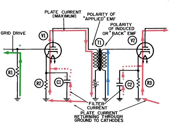
Fig. 1. The transformer-coupled AF amplifier-first half-cycle.
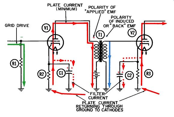
Fig. 2. The transformer-coupled AF amplifier-second half-cycle.
This is essentially a simple circuit. The relatively few currents involved and the colors they are shown in are:
1. Grid-driving current for tube V1 (green).
2. Plate current for each tube (red).
3. Transformer secondary current (blue).
4. Cathode filter current for each tube ( dotted red).
Fig. 1 is termed a positive half-cycle of operation because the control grid of V1 is being driven positive. The plus sign at the top of resistor R1 represents the instantaneous value of applied grid voltage and is consistent with the upward flow of grid-driving current through the resistor. The movements of this current, and the resulting instantaneous voltages at the grid, are controlled by preceding circuitry such as another voltage amplifier. It is this resulting grid-drive voltage we are seeking to amplify.
Maximum plate current through tube V1 coincides with maximum positive grid voltage. This heavy flow of plate current is indicated by the red line traversing the conventional plate-current path from cathode to plate within the tube and downward through the transformer primary. From here it can be drawn into the positive terminal of the power supply. The plate current completes its round trip by passing through the power supply to common ground. From here, it travels upward through cathode resistor R2 to the tube.
TRANSFORMER ACTION
Fig. 3 shows the graphical relationships between grid current and voltage, plate current and voltage, and transformer secondary voltage. Line 1 of this figure can be used to represent both the grid-driving current and the grid-driving voltage, since the current through a pure resistance is always in phase with the voltage across it. The reference line in the center of line 1 thus represents zero conditions for both current and voltage. When the current waveform crosses the reference line, this means no current is flowing at that instant and no voltage is developed across R1.
These conditions occur midway during each half-cycle depicted in Figs. 1 and 2.
Whenever the current sine wave of Fig. 3 is below the reference line, the current it represents is flowing downward through R2. This occurs during the last half of the second half-cycle and the first half of the first one. Or we could say that it occurs during the fourth and first quarter-cycles of operation, and that during these same periods the grid voltage has to be negative. The latter is indicated by the portion of the voltage sine wave below the zero reference line during these periods.
Sine-wave Symbology
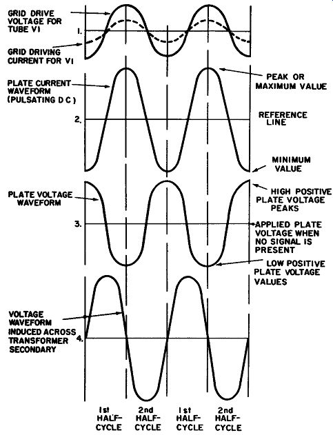
Fig. 3. Voltage and current waveforms in the transformer-coupled AF amplifier.
The use of voltage and current sine waves raises an interesting point. No other symbology available can present as much detailed information on a single cycle or on many cycles of operation as the sinusoidal, or sine-wave, symbology can. However, there are two important discrepancies in the way they are used which are traps for the unwary, as we shall soon see.
The definition of a sine wave is "a graphical representation, along a time reference line, of simple harmonic motion." The world is full of voltage sine waves, but the interesting fact is that voltage does not have motion . . . voltage does not move.
Only the current has motion, and the simplest and broadest definition of electric current is that it consists of electrons in motion. A negative voltage is defined as electrons in concentration.
Concentrations of electrons do not move around in a circuit; rather, the electrons flow from point to point. While electrons are moving they constitute a current. when they accumulate at any point, they constitute a negative voltage. When there is deficiency of electrons at any point, it constitutes a positive voltage.
So the discrepancy in a voltage sine wave is the implication, based on the definition of the sine wave, that all voltages have some kind of mysterious wave motion. For this reason, any time you see a voltage sine wave, remember that you are looking at a sine wave of quantity rather than motion. With this firmly in mind, you will be much better qualified to use the invaluable tool of sine-wave graphical representations of alternating voltages.
Since currents have motion, it is entirely proper to represent an alternating current by a simple harmonic-motion since wave. However, currents do not have polarity in the sense that a voltage has. Rather, they have directions of flow. All too frequently there is the tacit implication that any portion of a current sine wave above the reference or center line is "positive," whereas any portion below the line is "negative." The assignment of such polarities to current may have mathematical significance but is otherwise meaningless, particularly to the neophyte. Since current is always made up of electrons in motion, its flow direction during any portion of a cycle is important because it reveals (1) the points toward which electrons are being delivered to build up negative voltages, or (2) the points from which electrons are being depleted to build up positive voltages.
There has also been a tendency to refer to current as negative when we know it is composed of electrons flowing indisputably in one certain direction (such as the plate current of vacuum tubes). This is a holdover from olden days when negative electrons were not yet recognized as the prime current carriers in electric and electronic circuits. Current was universally assumed to flow from a positive to a negative voltage source. Later with the recognition of negative electrons as the current carriers, the term "negative current" was coined to describe them, the "positive-to-negative" or "conventional" current came to be known as "positive current" and this terminology still persists today.
There can be little genuine hope that this convention of "positive current" will ever disappear, since early researchers constructed much of the mathematics of electronics under the mis taken assumption that current flowed from positive to negative rather than vice versa. In fact, millions of words have been writ ten, based on this early assumption. When you get right down to it, though, it is easier for you to remember to "change the sign" that to rewrite all that literature! The alternating current in the primary winding is really a pulsating direct current. Changes in this primary current will in duce a voltage in the secondary winding of the transformer, and the induced voltage will be maximum when the primary current is changing at its maximum rate. Referring to the plate-current sine wave in line 2 of Fig. 3, you can see that the plate current is not changing whenever it is passing through its maximum and minimum values (at the end of the first and second half-cycles respectively) . A true alternating current is changing at its maximum rate whenever it is changing direction--in other words, whenever its graphical representation is crossing the reference line. Since plate current is a pulsating direct current, it always flows in the same direction (clockwise in the usual circuit diagram), unlike a true alternating current which flows in both directions. For this reason it is necessary to treat pulsating direct current as an alternating current. The additional convention devised to accomplish this is to look upon the plate current as consisting of two separate but related currents-a pure direct current (the value of which is indicated by the reference line in line 2) , and an alternating component superimposed on the direct current.
The reference value of plate current is the amount which will flow through the tube when no signal voltage is applied to the grid. This occurs only twice each cycle. Midway in the first half cycle, the application of a positive voltage to the grid will increase the plate current. A negative voltage will decrease the plate current, midway in the second half-cycle.
The voltage polarities shown at the tops of the primary and secondary windings in Fig. 1 are chosen to coincide with that instant when the plate current is increasing at its maximum rate midway in the first half-cycle. We see from line 4 of Fig. 3 that the voltage induced across the secondary winding has its maximum positive value at this instant. This voltage is applied to the control grid of vacuum tube V2. As a result, maximum plate current flows from cathode to plate in V2.
These voltage polarities are normally referred to as applied emf or back emf. In Fig. 2 these polarities are reversed-because the plate current is decreasing at its maximum rate-in the middle of the second half-cycle. The plate voltage is considered to be increasing in the positive direction, also at its maximum rate. This is the reason for the plus sign at the top of the primary winding in Fig. 2; it indicates the positive polarity of the applied emf across the primary winding at this instant.
Both tubes in this circuit employ the type of self-bias known as cathode biasing. Note the small resistor in series between the cathode and ground; plate current must flow through it before reaching the tube. When cathode-biasing is used, the plate current must flow at all times. Otherwise the positive cathode bias voltage would fall toward zero. This would change the grid-to cathode voltage difference (called grid bias) in such a direction that more plate current would flow. Consequently, the use of cathode biasing automatically signifies that a tube is being operated under Class-A conditions-by definition, a tube in which plate current is flowing throughout the entire cycle.
The process of bypassing the cathodes with filter capacitors C1 and C2 has been indicated on the circuit diagrams of Figs. 1 and 2. The filter currents which flow in and out of ground be low these capacitors are indicated in dotted red lines. Since there is absolutely no difference between these filtering processes and the ones in the resistance-capacitance coupled amplifiers of the previous Sections, the cathode filtering process will not be re described here.
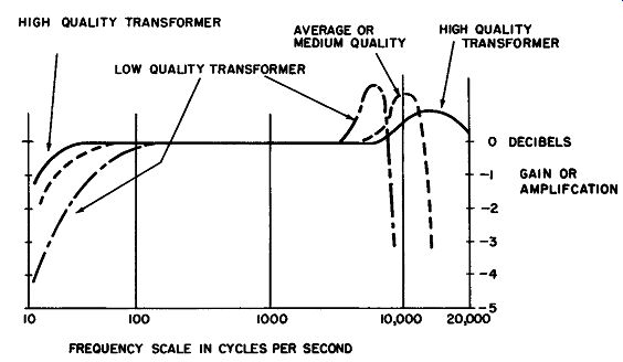
Fig. 4. Response curves of transformer-coupled AF amplifiers.
FREQUENCY RESPONSE
Fig. 4 shows some conventional frequency-response curves for an audio-frequency voltage amplifier using transformer coupling. The horizontal scale indicates that its range of usefulness is approximately the same as for the resistance-capacitance coupled amplifier previously discussed. Low-frequency operation is limited here by the extremely low inductive reactance which the transformer primary winding presents to the changing plate current. The applied emf developed across the primary winding is proportional to the inductive reactance of the primary winding through which the plate current must flow; inductive reactance is of course proportional to the frequency. Voltage, current, inductive reactance, and frequency are related by these two common formulas:
E=I X Xr, where,
E is the applied emf in volts, I is the AC component of plate current in amperes, Xr, is the inductive reactance in ohms; and: where,
Xr, is the inductive reactance in ohms,
f is the frequency of the applied AC component of plate current in cycles per second,
L is the inductance of the primary winding, plus any inductance coupled from the secondary, in henrys.
The average voltage amplifier using transformer coupling will have a good frequency response down to about 50 cycles per second. Below 50 cps the response deteriorates rapidly.
The high-frequency response of a transformer-coupled amplifier is limited by many inherent circuit capacitances. Figs. 5, 6, and 7 are adaptations of the equivalent circuit normally used in arriving at mathematical solutions for a transformer coupled amplifier. In addition to the inherent capacitances, an equivalent circuit also indicates the presence of such other inherent circuit constants as resistances and inductances.
A combined listing of the actual, or manufactured, circuit components, along with the inherent characteristics which act like components, would read as follows (refer to Figs. 5, 6 and 7):
C1-Output capacitance of tube (inherent).
C2-Shunting effect of capacitance between adjacent turns of primary winding (inherent).
C3-Capacitance between primary and secondary windings (inherent).
C4-Shunting effect of capacitance between adjacent turns of secondary winding (inherent).
C5--Input capacitance of next tube (inherent).
R1-Theoretical plate resistance of tube (inherent).
R2--DC resistance of primary winding (inherent). R3-Resistance representing eddy-current losses in primary winding (inherent).
R4--Resistance representing hysteresis losses in primary (inherent).
R5-Resistance representing direct-current losses in secondary winding (inherent).
RI-Input resistance of next stage (inherent).
L1-Leakage inductance of primary winding (inherent).
L2-Actual primary-winding inductance (manufactured).
L3-Actual secondary-winding inductance (manufactured).
L4-Leakage inductance· of secondary winding (inherent).
V1-Triode amplifier tube (manufactured). Fig. 5 shows the currents in the three audio-frequency ranges-low (green), middle (red), and high (blue )-in their passage through the amplifier circuitry. All currents are drawn as if they are momentarily in phase. Of course three currents of such widely different frequencies will rarely be in phase even momentarily. This has been done for illustrative purposes only; in general, the amplifier reacts independently to each current.
The plate current of medium frequencies (red) passes through the amplifier and receives maximum amplification. Like all others, this current must flow through all inherent circuit constants in its series path before passing through the power supply and back to ground. This path includes the theoretical plate resistance of the tube, the inherent DC resistance of the primary winding, the inherent leakage current of the primary, the theoretical resistance associated with hysteresis losses, and the primary winding of the transformer. In passing through the transformer primary, the plate current induces another current (also in red) in the secondary winding. This secondary current also must flow through the three inherent circuit characteristics which lie in its series path-the secondary leakage inductance, the DC resistance of the secondary winding, and the theoretical input resistance of the next amplifier stage.
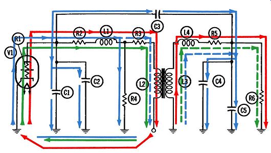
Fig. 5. Equivalent circuit of transformer-coupled AF amplifier-first half-cycle.
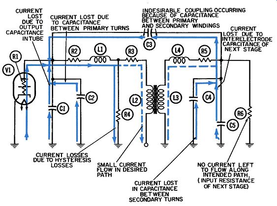
Fig. 6. Equivalent circuit of transformer-coupled AF amplifier at high frequencies-second
half-cycle.
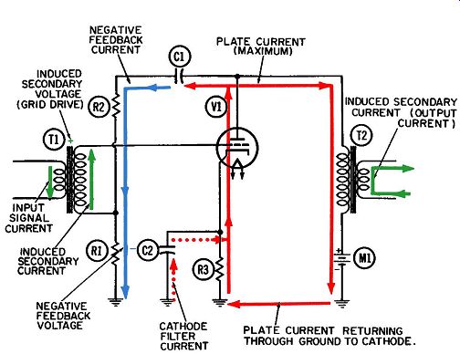
Fig. 7. Negative feedback amplifier circuit-first half-cycle.
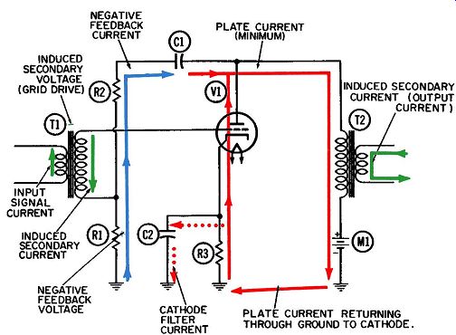
Fig. 8. Negative feedback amplifier circuit-second half-cycle.
Note that no significant portion of this middle-frequency current flows into any of the four inherent shunting capacitances which lead to ground; nor into the capacitance C3, which would couple it directly to the next stage rather than via normal trans former action. All these inherent capacitances are so small in value (10 or 20 micro-microfarads) that they have an extremely high reactance at low and middle frequencies. For this reason they do not bleed off any currents at these frequencies and consequently have no adverse effect on circuit operation.
The low-frequency current (in green) follows the same path through the amplifier as the middle-frequency current. Because transformer action is inadequate at very low frequencies, the low frequency current induced in the secondary winding is seriously weakened. Therefore, it is drawn as a dashed rather than a solid line, to indicate this attenuated condition.
Like the middle-frequency current, none of this low-frequency current flows into any of the inherent shunting capacitances, again because of their small size, and hence, high reactance at the low frequencies. As stated previously, the sole limitation on low frequency operation of a transformer-coupled amplifier is the in ability of the transformer, unless especially designed for the task, to induce sufficient secondary current at extremely low frequencies.
The high-frequency current, shown in blue in Fig. 5, has a rough time getting through the transformer-coupled amplifier.
Portions of it flow into every one of the inherent shunting paths.
These shunted portions must be counted as losses, since they no longer are available to flow into the primary winding of the transformer and induce a current in the secondary winding.
Fig. 5 is considered a positive half-cycle; at this time, the control grid (not shown) becomes positive and maximum plate current is released into the tube and external plate circuit. This accounts for the flow directions shown. The excess electrons in the plate current are driving electron current away from the plate and along the three unwanted shunt paths available to them.
These paths are downward into C1, (the output capacitance of the tube), downward into C2 (the capacitance between adjacent turns of the primary winding), and to the right into C3 (the inherent capacitance between adjacent turns in the primary and secondary windings of the transformer). None of these current components are available to do their primary task of flowing through the primary winding and inducing a current in the secondary-winding.
The high-frequency current in Fig. 5 is also shown flowing downward through R3 which represents the eddy-current losses in the primary winding. There will be some eddy currents induced in the transformer core at all frequencies; consequently, currents of all frequencies will incur some eddy-current losses. However, the amount of eddy-current losses increases as the square of the frequency. Hence, losses become most significant at the higher frequencies.
The small portion of current which succeeds in flowing through the primary winding is shown as a dashed line, to indicate the seriousness of the reduction. This small current induces a small current and voltage combination in the secondary winding-also shown as a dashed line. This secondary current is further reduced by the two inherent shunting capacitances, C4 and C5, and practically nothing is left to flow into input resistance R6.
Fig. 6 represents a negative half-cycle of the same high frequency current. During this half-cycle the currents previously driven downward in the four shunting capacitances--C1, C2, C4, and C5--are now being drawn upward from ground. These currents all flow very freely over these unwanted capacitive paths to ground as the frequency increases, leaving less and less current to do the necessary work.
The current coupled directly to the secondary via the inherent capacitance (C3) between adjacent turns of the two windings also reverses its direction each half-cycle. In Fig. 6 we see it flowing to the left, attracted of course by the inevitable rise in plate voltage whenever the plate current falls.
At first thought, this current does not really appear to be "lost"--after all, it is coupled to the secondary circuit and is therefore available to drive the control grid of the next amplifier stage, despite its unorthodox journey up to that point. This assumption is fallacious for several reasons, including the important one that current which reaches the control grid via this path will be out of phase with a current of the same frequency which traveled over the conventional path. Consequently, there would be two components of what was originally a single current, each attempting to drive the control grid independently of the other. As a result, the two would reach their peaks at different moments in the same cycle and partially cancel each other.
FREQUENCY DISTORTION
Of the three broad types of distortion-amplitude (nonlinear), frequency, and phase distortion--encountered in tube operation, it is possible to visualize at least one of them by reference to Fig. 5. Frequency distortion occurs when an amplifier provides un equal amplification of currents at different frequencies.
All currents whose frequencies fall within the band covered by the flat portion of the response curve (Fig. 4) will be amplified equally and passed equally by the coupling network. Hence, no frequency distortion occurs within this frequency band which is shown in red in Fig. 5. However, the low-frequency currents (in green) are amplified very poorly because of transformer limitations, and the high-frequency currents suffer because of all the losses caused by undesired capacitances. Thus, the low, medium, and high-frequency components are not equally amplified. This is defined as frequency distortion.
Examples of amplitude and phase distortion were discussed in Section 2 and will not be repeated here since they are the same for all amplifiers.
NEGATIVE VOLTAGE FEEDBACK
Figs. 7 and 8 illustrate two half-cycles in the operation of a commonly used feedback circuit. In this circuit a portion of the plate voltage is coupled, or fed back, to the input (grid circuit). Since the plate voltage is normally out of phase with the grid voltage, this type of feedback is considered to be negative.
The circuit used here is a simple transformer-coupled voltage amplifier for audio frequencies. The only difference between this circuit and the preceding one ( other than the feedback connection from plate to grid, of course) is that the control grid is driven by a transformer rather than a resistor.
The necessary components of this circuit include:
R1--Portion of voltage-divider network used for developing feedback voltage.
R2--Remaining portion of voltage-divider network.
R3--Cathode biasing resistor.
C1--Blocking and coupling capacitor.
C2--Cathode filter capacitor.
T1--Input transformer of the voltage step-up type.
T2--Output transformer of current step-up type.
V1--Triode voltage amplifier tube.
M1--Power Supply.
Identification of Currents
The operating currents in this circuit which need to be identified include:
1. Input transformer primary and secondary currents (both in green).
2. Plate current of tube (red).
3. Feedback current (blue) .
4. Output current in output-transformer secondary (green)
5. Cathode filter current (dotted red).
Details of Operation
Fig. 7 shows what is called a positive half-cycle, because the driving signal delivered through the input transformer to the control grid becomes progressively more positive throughout the half cycle. The polarity of this voltage is indicated by the plus sign at the top of the secondary winding of input transformer T1. This is the voltage induced in the secondary by the input current flowing in the primary winding. The directions of current flow in the primary and secondary are at all times related to each other and to the instantaneous polarity of the induced voltage. This is in accordance with the normal principles of transformer action.
The positive-going signal on the control grid in Fig. 7 releases a large surge of plate current into the tube. The normal path of plate current is from cathode to plate, then downward through the primary winding of output transformer T2 and into the positive terminal of power supply Ml, through the power supply to ground and through it to the bottom of cathode resistor R3. From here the plate current flows upward and returns to the cathode.
With the feedback network (consisting of C1, R2, and R1) in the circuit, a portion of this surge of plate current electrons flows onto the right plate of capacitor C1. An equal amount of electrons are driven off the left plate of C1 and downward through R2 and R1; this is the current shown in blue. When electrons are flowing downward through this path, we know that the instantaneous voltage at any point along the path will be more negative than the voltage at any other point farther down the path, since electrons always flow from negative to positive. Hence we can infer that the voltage at the junction of R1 and R2 will be negative with respect to the ground at the bottom of R1.
Since the bottom of the: secondary winding of input transformer T1 is also connected to the junction of R1 and R2, the positive control-grid voltage resulting from the transformer action will be reduced by the amount of this negative voltage developed across R1. Since the driving and feedback voltages are out of phase, the feedback is considered negative.
The total voltage developed across R1 and R2 by the flow of feedback current is divided between the two in proportion to their resistances. This is a straight Ohm's-law relationship:
Er=IXRr = I (R1 +R2)
or, also, where, E1 =IX R1 E:!=lxR2 ET is the total voltage drop across R1 and R2, E1 is the voltage drop across R1, E:! is the voltage drop across R2, Rr is the sum of resistances R1 and R2, in ohms, I is the effective value of the alternating current, in amperes.
Let,
Then, and, R1 = 10,000 ohms.
R2 = 90,000 ohms.
I= 1 milliampere.
E1 = .001 X 10,000
= 10 volts, E:! = .001 X 90,000
= 90 volts,
~= 10V + 90V
= 100volts
Thus, the total voltage across network R1 - R2 is divided in the ratio of 9 to 1, which is the ratio between the two resistances. The effective value of the feedback voltage is 10 volts.
Fig. 9 shows a simplification of the voltage waveforms in this circuit. Line 1 is the alternating voltage, which is normally applied to the control grid via the input transformer. During the first half-cycle, this voltage increases continuously in the positive direction. Because the cathode is biased positive by the R3 - C2 filter combination, the grid is automatically biased an equal amount in the negative direction (since the true definition of grid bias is "the difference in voltage between grid and cathode"). Under the conditions indicated, the peak voltage swing at the control grid is slightly less than this bias value. Hence, the control grid never becomes positive with respect to the cathode and no significant amount of grid-leakage electrons will flow.
Line 2 shows the sinusoidal waveforms for plate current and plate voltage. Note that they are 180° out of phase with each other; when the plate current reaches its maximum value, at the end of the first half-cycle, the plate voltage will be at its minimum value.
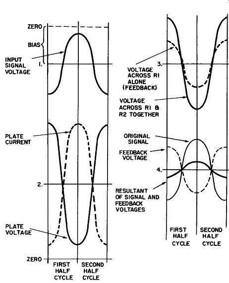
Fig. 9. Voltage and current waveforms in negative-feedback amplifier circuit.
This alternating component of plate voltage can all be considered as being coupled into the feedback network. This coupling is accomplished by means of the feedback current (shown in blue in Figs. 7 and 8), which works in and out of feedback capacitor C1. This current suffers negligible losses and phase shift; so the alternating voltage developed across the two series resistors (line 3 of Fig. 9) is an exact replica of the alternating component of plate voltage. The reduced portion in dashed lines represents the amplitude and phase of the voltage developed across feedback resistor R1 and fed back to the grid from the plate.
Line 4 is the control-grid voltage redrawn with the feedback voltage superimposed on the same axis. Because the two voltages are exactly out of phase, they tend to cancel each other out. The values of the resistors must be so adjusted that the alternating voltage applied through the transformer to the control grid is at least slightly larger than the feedback voltage. Otherwise, the resultant voltage will not have sufficient amplitude to provide the necessary excitation.
It will be apparent that the grid is actually being driven by the smaller voltage indicated in line 4 as the "resultant grid voltage," rather than by the original alternating voltage indicated in line 1.
This implies that smaller pulsations of plate current will occur.
This will result in smaller swings of plate voltage, and also less feedback current through the two resistors. Hence, the feedback voltage will likewise be smaller. Thus, the indicated amplitudes of the four voltage waveforms must be considered gross approximations only.
During the second half-cycle (Fig. 8), the grid driving voltage goes negative. The greatly reduced plate current which results is accompanied by a rise in the plate voltage, as indicated by the waveforms in line 2 of Fig. 9. This is the opportunity for electrons to flow off the right plate of capacitor C1. An equal number of electrons are drawn upward through the voltage-divider net work, making the feedback voltage positive at the junction of R1 and R2. Since this is also the same half-cycle the input trans former is trying to make the grid negative, we see that these two voltages still oppose each other. As indicated in line 4 of Fig. 9, the algebraic sum of these two voltages, at the end of the second half-cycle, is a small negative voltage.
This is called voltage feedback because it in effect is "tapped off" from the voltage changes occurring at the plate, even though the feedback voltage across the voltage divider owes its existence to the feedback current (shown in blue). Although we have shown the feedback loop from the plate to the grid of the same tube, the feedback voltage can be (and often is) taken from other points. The only requirement is that the feed back voltage be 180° out-of-phase with the signal voltage. For example, the feedback voltage could be taken from the plate of the last tube in a three-stage amplifier and applied to the grid of the first stage. Thus, any variations introduced by any of the three tubes would be cancelled out.
Also, the two forms of feedback discussed in the previous Section (positive voltage and negative current) can also be used with the transformer-coupled amplifier. Since operation is the same, they will not be discussed again here.
Cathode-Filter Circuit
The cathode filtering current, shown in dotted red, reflects withdrawals of electrons from the ion pool, on the upper plate of C2 during each first half-cycle or additions of electrons to the pool during the second half. As electrons are added to or withdrawn from the plate of C2 an equal number flows to or from ground to the bottom plate.
Thus, capacitor C2 aids in keeping the cathode voltage constant, by supplying electrons when the tube current is maximum, and storing them when it is minimum.