INTRODUCTION
Power supplies are the energy sources that are required to operate any electrical equipment, including electronic equipment. All types of electronic equipment--from the simplest AM radio to complex computers; from a child's cassette player to the most sophisticated space electronics-need some kind of power supply.
One goal of this guide is to show how to build various types of power supplies-from unregulated supplies to regulated switching supplies. With photographs and other illustrations, Building Power Supplies lists the components to use, shows how to interconnect the components to construct a power supply, and shows performance measurements of the completed assembly.
However, Building Power Supplies has another goal-to help you under stand the function of each component and the basic principles that are at work as the components perform their functions. If you already know the basic principles, the material in SECTION 1 can serve as a refresher, or you may chose to skip ahead to SECTION 2.
POWER
What is power? Power is the rate at which energy is used. A common unit of electrical power is the watt. A watt is the use of one joule of energy per second.
A watt-hour (the unit you see on your monthly electrical bill) is the supply of one watt for one hour, or one joule per second for 3600 seconds. A joule is the amount of energy that one would expend lifting a kilogram (1,000 grams = 2.2 pounds) about 10 centimeters (about 4 inches).
Power supplies for electronic equipment commonly have a wattage rating as a measure of the energy that can be delivered. Technicians and engineers know that the power supply voltage (in volts) times the current (in amperes) delivered to its load (the circuit to which the power is being supplied) is the watts of power supplied. For example, a power supply delivering 5 volts at 10 amperes to its load is providing 50 watts of power.
DC POWER
The most common type of power supply that all of us recognize is a battery.
Switch on your flashlight and the batteries inside supply current through the completed circuit to the light bulb. The current through the filament of the light bulb causes it to glow. Power flows from the battery through the light bulb. If the flashlight uses two 1.5-volt batteries (for a total voltage of 3 volts) and the current supplied to the light bulb is 0.1 ampere, the power supplied is 0.3 watt.
The simple circuit for the flashlight is shown in Figure 1-1a. This representation of an electrical circuit is called a schematic diagram. Standard symbols are used on schematic diagrams to represent the various components.
Notice that the battery symbol is a combination of alternating short and long parallel lines, with the short line indicating the negative (-) terminal.
Figure 1-1b shows a graphical plot of the current supplied by the battery in the circuit of Figure 1-1a. The current is constant against time and always in the positive direction. This current is called direct current (abbreviated as dc) because the current always flows in one direction.
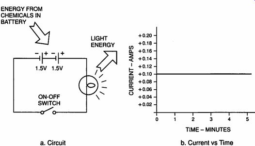
a. Circuit; b. Current vs Time
Figure 1-1. Simple DC Circuit
Battery
A battery is an electrochemical power source. The basic building block of a battery is the electrochemical cell. Higher battery voltages are obtained by connecting several cells together in series. This is how the word "battery" was derived. The cell cross-section shown in Figure 1-2a and the schematic shown in Figure 1-2b show a battery supplying current to a load of series-connected resistors.
As shown in Figure 1-2a, an electrochemical cell contains two plates, called the negative and positive electrodes, and a liquid or semi-liquid between the electrodes, called the electrolyte. When a circuit (conductive path) is completed between the terminals of the electrodes, a chemical reaction takes place between the positive electrode and the electrolyte that "pulls" electrons from the circuit to the positive terminal and into the electrolyte. An opposite reaction takes place at the negative electrode, "pushing" electrons out the negative terminal and into the circuit. Electrons and positive ions flow in the electrolyte to maintain the chemical reaction.
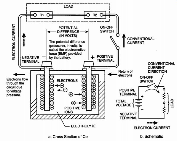
Figure 1-2. Batteries Supply Current to a Load
In Figure 1-2a, two directions are shown for the current in the circuit across the battery. One is electron current; the other is conventional current.
Electrons have a negative charge and flow from a point of negative voltage to a point more positive in voltage. Because early scientists who discovered electricity assumed that conventional current was the movement of positive charges (opposite from electrons), the conventional circuit current direction is opposite to the electron current direction.
Conventional current direction is the standard most commonly used by the electrical and electronic industries; therefore, it will be used in the remain der of this guide. Just remember, electron current will be in the opposite direction to the conventional current direction shown.
The chemical reaction develops a potential difference, called voltage, between the positive and negative terminals. Voltage is measured in units of volts. The pressure caused by the voltage is called the electromotive force. The number of electrons that actually flow through a conductor per second is called current, and is measured in units called amperes, commonly called amps. The voltage of a battery decreases as the battery supplies current to its load; therefore, batteries are commonly rated in "ampere-hours." This rating specifies the number of hours the battery can supply one ampere of current before the battery voltage decreases to a specified minimum value. For batteries that are designed to supply less than one ampere, this rating is expressed in "milliampere-hours," where one milliampere equals 0.001 ampere.
Primary and Secondary Batteries
Batteries are available in many types and voltages for many different purposes. Some are rechargeable (secondary cells) and some are non-rechargeable (primary cells). An example of a primary battery is the alkaline cell used in everything from flashlights to cameras to portable stereos. Examples of secondary batteries are the nickel-cadmium (Ni-Cd) batteries in some cordless tools, and the lead-acid batteries used in automobiles. Batteries are constantly being improved to increase the power delivered or to reduce the physical size required for a given power. Such developments increase their use in portable electronic equipment.
DC Generator
Another power supply for direct current is a dc generator. To understand the operation of a generator, you must understand the basic principles at work when a wire is moved in a magnetic field.
Generator Principles
Look at Figure 1-3. Here a loop of wire is mounted on a shaft and positioned in a magnetic field. The magnetic field, represented by lines in Figure 1-3, runs from the North pole of the magnet to the South pole. This field is invisible, but it is present. You know this is so because if a nail is brought close to the magnet it will be pulled to the magnet. The lines are made visible in Figure 1-3 to illustrate the principle. Notice that a voltmeter is connected across the ends of the wire loop. The loop's 90 degree position is as shown-the loop sides are closest to the pole pieces, and the face of the loop is parallel with the magnetic field.
Now, if the loop starts at 0 degrees and is rotated rapidly clockwise 180 degrees, the voltmeter needle will deflect to indicate a momentary voltage and then fall back to zero. When the loop cut across the magnetic field lines, an electromotive force was generated in each side of the wire loop to cause current in the same direction through the meter circuit and deflect the meter.
The amplitude of the generated voltage depends on three factors: the strength of the magnetic field, the speed of the rotating loop, and the number of turns of wire on the loop. Increasing any factor increases the generated voltage.
If the loop is again rotated clockwise another 180 degrees, the voltmeter needle will again deflect, but in the opposite direction. However, if before the second 180-degree turn, the meter leads were reversed, the meter needle would deflect in the same direction as for the first rotation. Thus, if the loop is continually rotated while the leads are reversed at each 180-degree point, the generated voltage plotted against time will look like the waveform shown in Figure 1-4a. This is the basis of a direct-current generator.
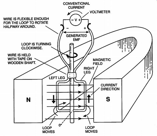
Figure 1-3. Simple Generator
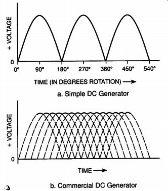
Figure 1-4. DC Generator Voltage Versus Time
Commercial Generator
A commercial dc generator has many windings, each with many turns of wire, wound on an iron core. This assembly is called an armature. The ends of the windings connect to split slip rings, called the commutator, on the generator shaft. The output terminals are connected to sliding connectors, called brushes, which are in contact with the commutator. This combination reverses the winding connections to the output terminals as the armature rotates so that the generated voltage is always the same polarity. The windings are positioned on the generator shaft so that the output voltage waveform looks like that shown in Figure 1-4b when plotted against time. The output voltage is nearly constant and when connected to a circuit load, the current in the circuit will flow in only one direction. It will be direct current from a dc generator-a dc power supply.
As mentioned above, the voltage level produced by a generator depends on the number of turns in the generator windings, on the speed at which the generator shaft is driven, and on the strength of the magnetic field. The maximum current that a dc generator can produce depends on the size of the wire in the generator windings, the design of the commutator and brushes, and the way the generator is cooled. The rated power wattage is equal to the rated voltage times the rated current.
Induction
The voltage in the loop that caused a current in the meter connected to the loop is said to be induced by the magnetic field. The induction can occur either by moving the loop through the magnetic field, or by moving the magnetic field through the loop. The principle of induction is very important to the dc generator, to the ac generator discussed next, to inductors, and to transformers discussed in SECTION 2.
AC POWER
Alternating current (ac) differs from dc in that the circuit current doesn't flow only in one direction; it reverses and flows in the opposite direction as well. It changes direction at regular time intervals. The regular periodic rate at which the current reverses direction is called the frequency. AC-powered equipment must be able to operate at the frequency at which the alternating current is generated.
AC power runs trains, factories, and the appliances in our homes. What makes it especially useful is that transformers can be used to convert ac to different voltages, as we will see in SECTION 2.
AC Generator
The primary source of ac power is the ac generator, which is usually called an alternator. It is very similar to the dc generator. Look again at Figure 1-3. Recall that when the loop coil was rotated the first 180 degrees, the meter deflected in one direction; and if continued through a second 180 degrees without reversing the leads, the meter deflected in the opposite direction. The change in direction of the meter's deflection meant that the current changed its direction through the meter. The voltage induced in the loop was in the opposite direction so the current in the circuit changed direction.
Look at Figure 1-5a. The shaft on which the loop of wire of Figure 1-3 is mounted is now driven by a motor that turns the loop so it makes 60 complete rotations each second. The ends of the loop are connected to slip rings so the meter is connected to the loop through brushes on the slip rings at all times as the loop turns. The voltage indicated by the meter as the loop turns is shown in Figure 1-5b. Notice that in the first 180 degrees, the voltage is positive, and in the next 180 degrees, the voltage is negative.
As the loop turns, the voltage repeats itself each 360 degrees, or each cycle.
If the loop makes one 360 degree rotation in 1/60 of a second, then 60 cycles of voltage will be induced or generated in one second, and the frequency of the ac voltage is 60 cycles per second. The official name for "cycles per second" is "hertz," so the generated voltage has a frequency of 60 hertz. If the number of turns on the loop of wire is increased until the generated voltage is 110 volts, then a 110VAC, 60Hz ac generator will have been constructed. This is the principle of an ac generator-the primary ac power supply. Because of its simpler construction (continuous slip rings instead of a split commutator), and because dc is easily derived from ac, as we will see in SECTION 2, the ac generator or alternator is much more widely used than the dc generator.
Inductance
Let's review up to this point. A wire cutting across a magnetic field will have a voltage induced in it and there will be a current in the wire when it is connected in a complete circuit. There is a counter principle to this as shown in Figure 1-6a. When there is current in a wire, a magnetic field will be formed around the wire as shown. As current increases in the wire, the magnetic field increases around the wire; as current decreases in the wire, the magnetic field decreases around the wire. If other wires are near the wire carrying the varying current, as shown in Figure 1-6b, the varying magnetic field cuts across the wires and induces a voltage in them. The varying magnetic field expanding and collapsing around the nearby wires is the same as if the magnetic field were stationary and the nearby wires where cutting across the magnetic field. This is the principle of the transformer, which will be discussed further in SECTION 2.
Inductors also use this principle to produce an electrical property called inductance.
Inductive Reactance
When current passes through wire, which is wound in a coil, a magnetic field will be produced around the coil, which is the result of the interactions of the magnetic fields around each loop of wire in the coil. With alternating current through the coil, the field expands and collapses around the coil. The expanding and collapsing field induces a counter voltage in the coil that opposes the varying current that is producing the original field. This opposition or resistance to ac is called inductive reactance. It has the symbol X; and is calculated using the following equation with f as the frequency in hertz and L as the inductance of the coil in henrys; w is a constant equal to 3.1416:
X_L = 2π f L
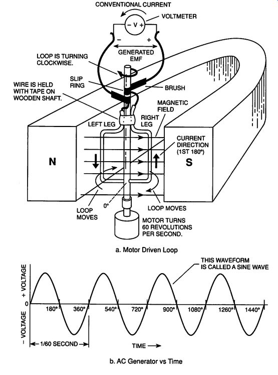
Figure 1-5. AC Generator. a. Motor Driven Loop ; b. AC Generator vs Time.
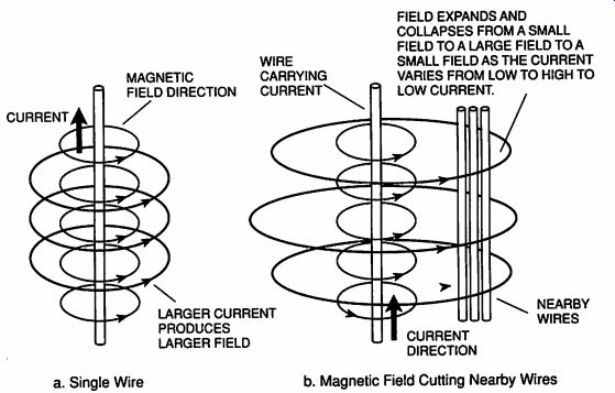
Figure 1-6. Magnetic Field Around Wires Carrying Current--- a. Single Wire
b. Magnetic Field Cutting Nearby Wires---FIELD EXPANDS AND COLLAPSES FROM
A SMALL FIELD TO A LARGE FIELD TO A SMALL FIELD AS THE CURRENT VARIES FROM
LOW TO HIGH TO LOW CURRENT.
Inductance depends on the size (area and length) of the coil, the number of turns, and the permeability of the material on which the coil is wound.
Permeability is a measure of how easily a material can be magnetized. Notice that as the frequency of the varying current increases, the inductive reactance increases. This will be important later when inductors used in power supply filters are discussed.
The unit of inductive reactance is ohms, which is the same unit used for the resistance of a resistor. The total opposition (impedance) by an inductance in an ac circuit is the sum of the inductive reactance and the dc resistance of the wire in the inductor. An inductor with dc or very low frequency ac flowing through it has an impedance close to the dc resistance of the wire used to wind it. As the frequency increases, the impedance increases dramatically because the inductive reactance increases dramatically.
SUMMARY
In this SECTION, we have discussed the basic sources of dc and ac electricity - lectrochemical (batteries) and electromechanical (generators, alternators).
We have illustrated how magnetic principles are used in generators and alternators to generate electricity and in inductors to produce inductive reactance, an electrical property that opposes alternating current. In SECTION 2, we will see how the magnetic principles are used in transformers, one of the main components in unregulated power supplies.
Next: SECTION 2 UNREGULATED POWER SUPPLY SYSTEMS
Building Power Supplies (Article Index)
Also see:
Link |