INTRODUCTION
Most electronic equipment circuits require a power supply that provides a dc voltage at some maximum dc current. Batteries can be used to provide this energy for equipment that has a low power requirement or if it is normally used intermittently. Another possible power source is a dc generator, however, neither batteries nor dc generators are practical or economical for many types of electronic equipment. Since the 110VAC, 60-hertz power distributed by the electric power company is readily available, most electronic equipment operates from a power supply that converts the ac line voltage to a dc voltage.
The basic unregulated dc power supply functions are transformation, rectification, and filtering. These functions are indicated in Figure 2-1, along with the input and output waveforms for each function.
The transformation function input is the 110VAC from the utility line. Its ac output voltage, which can be lower or higher than the input voltage, is the input to the rectification function. The rectification function output is a dc voltage, but because it has large amplitude variations, it is called "pulsating dc." The filtering function reduces the large amplitude variations so that the output is a dc voltage with only a small "ripple" voltage riding on it. This basic power supply is called an unregulated dc power supply because its output varies with changes in the ac input voltage as well as changes in the load on the power supply output. To understand the operation of this power supply, let's discuss each of the functions in detail.
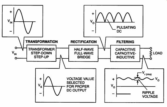
Figure 2-1. Unregulated DC Power Supply
TRANSFORMATION
Transformation provides two primary functions:
--It changes the line voltage value to the voltage value required to produce the proper dc voltage output.
--It electrically isolates the electronic equipment from the utility power line.
Transformers
A transformer is the component that performs the transformation function. As shown in Figure 2-2, it consists of at least two coils of wire wound on the same iron core. The coil of wire receiving the input voltage is called the primary; the coil providing the output voltage is called the secondary. Many times there are two or more secondaries. The basic operating principle of a transformer is induction, which was discussed in SECTION 1. Varying current from an ac voltage applied to the primary creates a changing magnetic field in the iron core. This magnetic field, coupled to the secondary through the core, cuts the secondary windings and induces an ac voltage in each turn of the secondary.
Thus, energy is transferred from the primary to the secondary by the varying magnetic field without any electrical connection between them.

Figure 2-2. Transformer Construction
Isolation
Because the energy transfer is accomplished only by the magnetic coupling between the primary and the secondary, the secondary and any circuits connected to it are isolated from the primary and any circuits connected to it. This is important for safety because the primary is connected to the high current supply of the utility line. Without such isolation, there is a serious shock hazard. Another advantage is that no dc connection exists between circuit ground in the primary circuit and circuit ground in the secondary circuit.
Turns Ratio In an unregulated power supply, the transformation function must provide the ac output voltage value required to produce the proper dc output voltage.
This is easily accomplished in a transformer by varying the ratio of the number of secondary turns (N;) to the number of primary turns (N,). The ratio is formed by dividing N, by N _ that is, N,/N,. The secondary voltage can be less than or greater than the primary voltage just by varying the turns ratio, N,/ Ng:
The amount of voltage induced in a turn of the secondary winding is the same as the voltage induced in a turn of the primary. The voltage induced in each turn of the primary, e _ is the primary voltage, V _ divided by the primary turns, N,. In equation form, it is:
e, = V,/N,
If the same voltage is induced in each turn of the secondary winding, then the secondary voltage, V _ is the number of secondary turns, N _ times the induced voltage, e,. In equation form, it is:
V,=N; Xe,
By substituting the value of e, from the first equation into the second equation, V_s equals the turns ratio times V _. In equation form, it is:
V,=N/N, X V,
Knowing that the secondary voltage is the primary voltage times the turns ratio, it is easy to see how the transformer can be used to vary the voltage level of the ac voltage used in the unregulated power supply system. Let's look at a couple of examples using a schematic symbol for a transformer like that shown in Figure 2-3a.
Step-Down Transformer
If the secondary turns are fewer than the primary turns, the secondary voltage is less than the primary voltage. This is a step-down transformer. In the example shown in Figure 2-3b, the turns ratio is 0.5 and the primary voltage is 110VAG _ therefore, the secondary voltage is 110VAC X 0.5 = 55VAC.
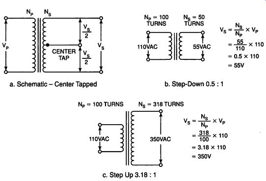
Figure 2-3. Transformers. a. Schematic - Center Tapped; b. Step-Down 0.5 :
1; c. Step Up 3.18: 1
Step-Up Transformer
If the secondary turns are more than the primary turns, the secondary voltage is greater than the primary voltage. This is a step-up transformer. In the example shown in Figure 2-3c, the turns ratio is 3.18 and the primary voltage is 110VAC; therefore, the secondary voltage is 110VAC X 3.18 = 350VAC.
Power Transfer and Efficiency
The power flowing out of the secondary in relation to the power flowing into the primary is given by:
V,XxL=V,XL Xn
... where n is the transformer efficiency. If the efficiency were 100% or n = 1, the power out would be equal to the power in. Therefore, if V_s is smaller than V _ I;
must be larger than 1, and if V_s is larger than V _ I, must be smaller than [. A power transformer's efficiency usually is between 85% and 95%.
AC VOLTAGE VALUES
A dc voltage usually has only one measured value. An ac voltage, because it is continually changing, can have several different measured values depending on how it is measured. Study these voltage values because they are important in power supply design. They will be used later in this guide for the project designs.
Figure 2-4 shows the common ac power-line voltage waveform plotted against time. The time axis is also calibrated in the degrees of rotation of the ac cycle. For the first 180 degrees, the voltage is positive; for the next 180 degrees, it is negative. Because the power-line frequency is 60 hertz, a 360 degree rotation cycle takes one sixtieth of a second.
V_rms
The value of the power-line voltage is typically stated as 110VAC, but this value is really 110Vrms.. V,...., as shown in Figure 2-4, is the value normally measured on an ac voltmeter. V _ is the usually stated value of an ac voltage because it is an ac voltage that provides the same energy to a resistive load as an equivalent dc voltage.
V_pk and V_pp
Note in Figure 2-4 that other values can describe the ac voltage. The peak voltage, Vpp is the maximum value of the voltage in its cycle. The peak-to-peak voltage, Vpp is the total value of the voltage from the maximum positive peak to the maximum negative peak. For a sine-wave voltage (which is a voltage that varies as the mathematical sine function of the angle of rotation) as shown in Figure 2-4, V _; equals 70.7% of the peak voltage ( V_rms = 0.707 X V _). Conversely, V _ is 141.4% of the V _, voltage (V _ = 1.414 X V _,). The peak-to-peak voltage for a sine-wave is twice the peak voltage (V _ = 2 X V _).
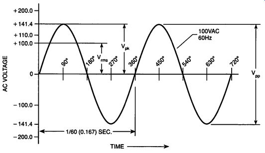
Figure 2-4. AC Voltage Values
RECTIFICATION
Rectification converts an ac voltage into a dc voltage. The component that performs the rectification function is called a rectifier.
Rectifier
The rectifier is a type of diode. Simply stated, it is a one-way valve for electricity. As indicated in Figure 2-5, it allows electrons to flow freely in only one direction, called the forward-biased direction, where the anode voltage is more positive than the cathode voltage. In the opposite direction, called the reverse-biased direction, electrons cannot flow easily. In this direction, the anode voltage is more negative than the cathode voltage.
V_F
A forward-biased diode is not like a piece of wire because it has enough resistance to produce a significant voltage drop across it. The forward-biased voltage drop, shown as V_F in Figure 2-5a, varies according to the type of material used in the diode. A commonly used silicon diode has a V_F of 0.5-0.7V, and a germanium diode has a V_F of 0.2-0.3V.
V_R and PIV
The maximum reverse-bias voltage, shown as V_R in Figure 2-5b, that can be applied to a diode is called the peak inverse voltage (PIV). If this voltage is exceeded, the anode-cathode junction may break down and allow a large current to flow in the reverse direction. If breakdown is exceeded, the diode is usually permanently damaged.
Half-Wave Rectifier
A simple half-wave rectifier circuit has a diode connected in series with a transformer secondary output as shown in Figure 2-6a. The input primary voltage is a power-line, 60-hertz, sine-wave voltage. The positive cycle alter nation is labeled A and the negative one is labeled B. The polarities of the primary and secondary voltages are noted for each alternation.

Figure 2-5. Diode: A One Way Valve for Current. a. Forward Biased. b. Reversed
Biased
On alternation A, diode D1 conducts because its anode is more positive than its cathode. A voltage equal to the secondary voltage (minus the diode's Vp) is developed across the load, R,. On alternation B, D1 blocks current so no voltage is developed across R,. The secondary voltage appears as reverse volt age, Vy, across the diode. To withstand this voltage, D1's PIV must be greater than the secondary voltage's V_pk.
The output voltage (Figure 2-6a) is a series of 60-hertz, half-cycle alternations of the secondary voltage. The voltage is always in one direction and is known as "pulsating dc." If the area under the positive pulses is averaged over a complete cycle, the average dc voltage is 0.318 times the secondary's V _,.
A half-wave rectifier circuit is used for low current applications such as battery chargers and ac-dc adapters for calculators. Note that if a battery were placed across the dc output as a load, it would charge to the peak voltage of the secondary minus the V_s of the diode.
Full-Wave Rectifier
The rectifier circuit in Figure 2-6b converts both alternations of the secondary voltage to a dc voltage; therefore, it is known as a full-wave rectifier. A diode is in series with each secondary output and the center tap is grounded. The voltage between the center tap (See Fig.2-3a) and each secondary output is equal in value, but opposite in direction. When Vy, is positive, Vj, is negative.
D1 conducts during the A alternation and D2 conducts during the B alternation. The center tap is a common return for the current from each diode. Because both diodes conduct current to the load in the same direction, the pulsating dc has positive half-cycles on both alternations of the secondary voltage. The output is pulsating dc at 120 hertz with an average dc voltage of 0.636Vy,.
Only half of the secondary is used at one time; therefore, the transformer secondary output voltage must be twice that needed to provide the proper dc voltage. Also, each diode's PIV must be at least the full secondary's Vg.
Bridge Rectifier
The rectifier circuit of Figure 2-6¢ is called a full-wave bridge rectifier. It uses four diodes in a bridge network. One output terminal of the bridge network is a common ground for the return of the load current. The other output terminal is connected to the load.
D1 and D2 conduct on alternation A, and D3 and D4 conduct on alternation B. Both conducting paths deliver current to the load in the same direction.
The pulsating dc output is the same as the full-wave rectifier. The output dc voltage is the secondary voltage minus two forward diode drops. The diodes' PIV must be greater than the secondary peak voltage, Vy.
FILTERING
The pulsating dc output after transformation and rectification is not a satisfactory power source for most electronic circuits. The filtering function smooths the output so that a nearly constant dc is available for the load.

Figure 2-6. Rectifier Circuits. a. Half-Wave Rectifier. b. Full-Wave Rectifier.
c. Bridge Rectifier
The pulsating dc output from the rectifier contains an average dc value and an ac portion called a ripple voltage. A filter circuit reduces the ripple voltage to an acceptable value. Resistors, inductors and capacitors are used to build filters. None of these components have amplification. Resistors oppose current and normally function the same way in dc or ac circuits by not varying with frequency. Inductors oppose current changes, and their inductive reactance increases with frequency. Capacitors oppose voltage changes, and their capacitive reactance decreases with frequency. Let's take a closer look at capacitors and understand what they do.
Capacitor
A capacitor consists of two conductive plates separated by an insulator, called the dielectric, as shown in Figure 2-7a. When a dc voltage is applied across the plates, electrons collect on one plate and positive ions on the other. The difference in the electrical charges on the plates equals the voltage applied. If the voltage is removed, the electrical charges remain in place and maintain the voltage difference between the plates. In other words, the charge is stored by the capacitor. The charge storage characteristic gives a capacitor in a circuit the effect of opposing voltage changes. This effect is very important to the filtering function in dc power supplies.
The electrical unit of capacitance is the farad. A farad is a very large quantity so actual capacitors are usually rated in microfarads. One microfarad is 0.000001 (1 X 10^-6) farad.
Discharging a Capacitor
To understand how a capacitor is used in filtering, let's examine a capacitor's discharge characteristic. In Figure 2-7c, a capacitor has already been charged to a voltage V.. Switch S, which has been open, is closed and the capacitor discharges through resistor R. The voltage across the capacitor decreases as time passes according to the very predictable curve shown in Figure 2-7d. It is called an RC discharge curve because the time scale is in RC time constant units. To find the RC time constant (in seconds) for the discharge curve, multiply the resistance (in ohms) discharging the capacitor by the capacitance (in farads). If the capacitor is 10 microfarads (0.00001 farad) and the resistance is 100 ohms, one RC time constant is 0.001 second (100 X 0.00001 = 0.001). The resistance discharging a power supply filter capacitor is the power supply load.
The discharge curve of Figure 2-7d shows that V, will decrease to 37% of its original charged value in one RC time constant. In five RC time constants, the capacitor will be fully discharged. Analysis of the discharge curve reveals two important facts:
-- The larger the capacitance, the larger the RC time constant and the slower the discharge.
-- The smaller the resistance, the smaller the RC time constant and the faster the discharge.

Figure 2-7. Capacitors. a. Physical Construction; b. Schematic; c. Discharging
C; d. ischarging Curve
Capacitive Filter
The simplest filter is a single capacitor in parallel with the output from a rectifier. In Figure 2-8a, C_Fl, is the filter capacitor and R_L represents the power supply load. I_L equals V_o divided by R; (Ohm's law). Look at the waveform of V_o plotted against time. V_o increases rapidly to the peak voltage output from the rectifier as the first alternation half-cycle charges C_Fl. If there were no load (R_L=infinity), V_o would remain at the peak voltage and C_Fl would not have to be charged again; however, with a load of R, and a current of I, C;, starts to discharge as the rectified pulse decreases to zero. The discharge is according to the curve of Figure 2-7d, and the RC time constant is C, times R,. C, discharges to point A shown on the V, waveform. At point A, the next alternation pulse voltage increases above V, and recharges Cg, to the peak voltage again.
A filter capacitor must be large enough to store a sufficient amount of energy to provide a steady supply of current for the load. If the capacitor is not large enough, or is not being charged fast enough, the voltage will drop as the load demands more current.
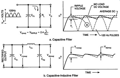
Figure 2-8. Filtering: a. Capacitive Filter; b. Capacitive-Inductive Filter
The RMS voltage of the variation in V, above and below the output dc value is shown as the ripple voltage, v _ in Figure 2-8a.
For a full-wave, 60Hz ac input, V_r(rms) is:
Vr(rms) = 2.4 1L/C_Fl
where I_L is in milliamperes, C_Fl, is in microfarads, and an RC discharge is assumed.
The equation can be rearranged to find C_Fl for a power supply that must supply I_L milliamperes of current and have a ripple voltage of Vr(rms).
C_Fl =2.4 I_L / V(rms)
Ripple Voltage
Ripple voltage is usually stated as a percent of the dc output voltage, V_o:
For example, let's assume a power supply must provide 10V dc at 200 milliamperes with a 1% maximum ripple voltage. Using the above equation, multiply 1 times 10 and divide by 100 to find that the ripple voltage must not exceed 0.1 volt. Then use the Cg, equation to find that C;, must be 4800 microfarads to meet the ripple requirement.
Additional filter components can be added, as shown in Figure 2-8b, to reduce the ripple voltage further. When Lg, is in henries, Cg, is in microfarads, and the source is a 60Hz, full-wave rectifier, the V _, of Figure 2-8b is:
Vi2gms) = Vrms) xX 1.77] Le Cr, =
--Basic Electronic Technology, Radio Shack No. 62-1394 1985 Texas Instruments, Dallas, TX.
VOLTAGE DOUBLER
A transformer can increase the voltage level of ac, but a transformer is relatively expensive and increases the weight and heat generation of a power supply. In some cases, a special type of rectifier circuit called the voltage doubler is used to provide a higher output voltage without using a larger and heavier step-up transformer.
Operation
Figure 2-9a illustrates the circuit and Figure 2-9b shows the output waveform.
The first A alternation forward biases D1 and charges C1 to V _. The first B alternation forward biases D2 and charges C2 to V _. Because C1 and C2 are connected in series with their polarities aiding, the output voltage, V _ is the addition of the two capacitors voltages, which is 2 X V _. Additional circuit segments can be used to form voltage triplers and quadruplers. Circuits such as this are useful for photo-flash power supply applications that require a high-voltage, high-current pulse for a short time period, and then allow a relatively long time before another pulse is required.
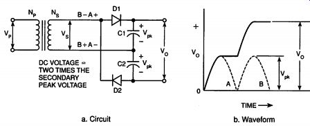
a. Circuit b. Waveform
Figure 2-9. Voltage Doubler
SUMMARY
An unregulated power supply provides the rated output voltage when the rated line voltage is input and the rated current is delivered to the load. If the line voltage increases or if the load current decreases, the output voltage increases. If the line voltage decreases or if the load current increases, the output voltage decreases. Thus, the output voltage is unregulated because it varies with line and load changes.
The basic functions required for unregulated power supply systems of transformation, rectification and filtering were discussed in this SECTION. The components that perform these functions were explained and their important parameters were identified. In the next SECTION, the circuits required for regulation will be added.
Prev: SECTION 1 Basic SOURCES OF DC AND AC POWER
Next: SECTION 3 Basic REGULATED POWER SUPPLY SYSTEMS
Building Power Supplies (Article Index)
Also see:
Link |