The proper placement of a television receiver, of course, depends upon such factors as the layout of the house, number and size of the individual rooms, lighting arrangement, location of power outlet, and antenna lead-in. In some cases, the type of power outlet is a matter of importance. For example, most receivers may be plugged into switched outlets. Some receivers provide digital readout, with channel number and the time displayed on the screen when so commanded (see Fig. 6-1). The digital clock should always be operated from an unswitched outlet; otherwise, the indicated time is likely to be in error.
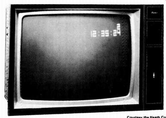
Fig. 6-1. TV receiver with digital clock and channel indicator.
The following points should be taken into consideration:
1. Do not place the receiver in such a position that direct illumination, such as light from a window, falls on the face of the screen. A certain amount of background illumination is desirable when viewing over long periods of time to reduce eyestrain.
2. Do not place the cabinet directly against the wall. Leave a 2-in, air space so that adequate ventilation will be ensured.
In addition, the receiver must be installed a sufficient distance from any heating device, such as vents and radiators, as the effect of heat will impair its operation or even dam age the receiver.
3. It is desirable to locate the receiver as far as possible away from sparking or gaseous electrical discharge devices, such as neon display signs and electrically operated cash registers.
4. If the receiver is to be connected to an outside antenna, proper attention should be given to the location of the antenna lead-in and the power outlet to prevent excessive length of these connector leads. A typical receiver location is shown in Fig. 6-2.
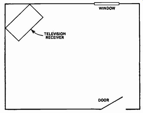
Fig. 6-2. Typical receiver location.
With respect to the decorative scheme of the home, most decorative authorities agree on the following points:
1. The room containing the television receiver should be so planned that viewers can enjoy a program without first upsetting and rearranging the room.
2. Lighting should be arranged so as to prevent the light from shining directly on the screen or into the viewer's face.
3. The television receiver should not be so dominant in design or location that viewers have to sit and face it when not in use.
Other factors, such as seating arrangements, type of chairs, use of stools or hassocks, and their individual characteristics ofcom fort and convenience must be left to individual taste and suitability. Some owners prefer to have their principal television receiver placed in a corner of the living room, while others prefer to have it or a second receiver in the family room, den, library, or study if such are available.
In recent years, a second or third television receiver has been added to many homes. Children's rooms, basement recreation rooms, and kitchens are popular locations for an additional receiver--often a portable receiver (Fig. 6-3), which can be rolled or carried anywhere in the house or even outdoors wherever power is available. All portable receivers are completely transistorized (except for the picture tube, of course), and some even operate on self-contained batteries that can be carried anywhere.
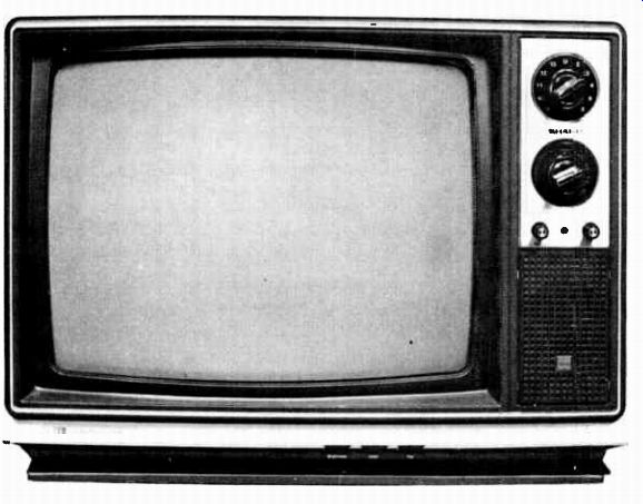
Fig. 6-3. Typical portable television.
Television Lighting-In the early days of television, many people would turn out all the lights and sit in the dark watching the bright spot of the television receiver on the other side of the room. Soon, the eyestrain from such a setup became apparent, and all types of special TV viewing lights made their appearance.
Improvement in the viewing screen of television picture tubes and education of the viewing public soon made all of this unnecessary. All that is necessary is to make sure that the lighting (either sunlight or artificial) does not cause a glare on the screen or shine in the viewers' eyes while they are watching the receiver.
TELEVISION CONTROLS
Any piece of electronic equipment must have provisions for adjustment before proper operation can be obtained. The television receiver is no exception-every television receiver contains several controls that are varied to obtain the proper reproduction of the picture and sound transmitted by the station.
Some adjustments must be varied more often than others; hence manufacturers place some controls on the front side or top of the TV cabinet, where they are readily accessible to the operator. Other controls require less frequent adjustments, and so they are located on the rear panel of the chassis, the chassis itself, or on the neck of the picture tube. The readily accessible controls are termed operator controls, while the others are called service adjustments.
Manufacturers differ, however, in the number and type of controls they include for operating controls and the ones they make service adjustments. In addition, depending on the chassis design, some receivers will contain controls that are not on others. Also, the terms used to identify the same control vary. Typical service adjustments are shown in Fig. 6-4.
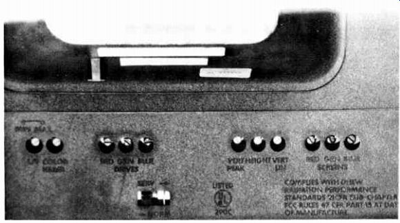
Fig. 6-4. Typical service adjustments.
In general, however, the operating controls affect the program selection and the picture and sound quality, while the service adjustments (also called preset controls) affect picture quality, position, or spacing.
The following controls are most often placed as operating controls; however, as mentioned previously, all these controls will not be accessible in all receivers:
1. On-off switch and volume control
2. Channel selector
3. Fine-tuning control
4. Contrast control
5. Brightness control
6. Horizontal-hold control
7. Vertical-hold control
Most of these controls will not need adjustment during normal reception; however, they require more frequent adjustment than the other controls. As receiver design improves, these controls require less frequent adjustment, and so they may be moved to the rear of the chassis. For example, the last two controls listed are not included as operator controls by many manufacturers.
Dual Controls--In order to simplify the operation to improve the appearance of the cabinet, dual controls, with concentric knobs, are often employed. That is, the controls are arranged in pairs of two: a small inner knob and a larger outer knob, each affecting only one-half of the dual control. For example, the channel-selector and fine-tuning controls are commonly dual knobs; also, contrast and brightness controls are often similarly arranged.
Some manufacturers arrange some of the controls behind a hinge panel (Fig. 6-5). Controls that are included behind covers do not need to be reset each time the receiver is operated, and so their lack of accessibility is more than compensated for by the improvement in appearance.
THE TEST PATTERN
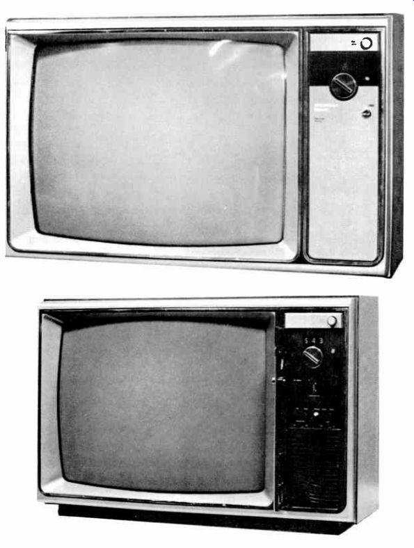
Fig. 6-5. Controls hidden behind swing-out panel.
Before the operation and proper adjustment of the various controls can be understood, the test pattern and the part it plays in adjustments must be understood. Figure 6-6 shows standard test patterns. Many TV stations transmit patterns similar to these before they begin transmitting regular programs for the day.
Such patterns are also available from pattern generators-a piece of test equipment (see Fig. 6-7).
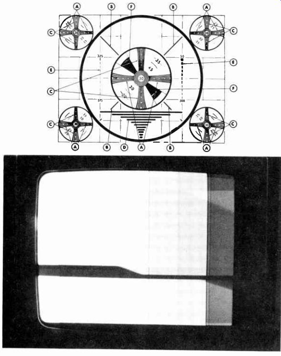
Fig. 6-6. Typical test patterns.
Station test patterns usually will not include all the features shown in Fig. 6-6, but they will include station identification.
When a station is transmitting a test pattern, the sound will consist of a single tone transmitted continuously. Many stations begin their programs so early in the day that they do not transmit test patterns.
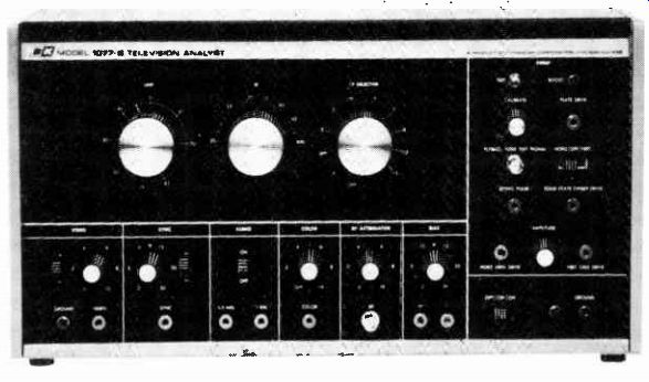
Fig. 6-7. Service-type pattern generator.
The function of a test pattern is to furnish an accurate means of comparing the picture that appears on the picture tube with that set by the television camera. If the two are identical, it would indicate completely perfect transmission and reception through out the entire system. Such a condition, of course, is impossible to accomplish; however, it can be closely approximated. In addition, such factors as aspect ratio, resolution, linearity, contrast, brightness, and focus can be easily checked using the patterns in Fig. 6-6.
Aspect Ratio
The aspect ratio of a picture determines its proportions. The television standards followed by all United States television stations state that the aspect ratio shall be 3:4, which means that the height is 3/4 times the width of the picture. The faint vertical and horizontal lines across the pattern in Fig. 6-6 can be used to determine the aspect ratio. Note that there are 6 horizontal lines and 8 vertical lines. Thus, the picture is divided in 6 parts vertically and 8 horizontally, giving an aspect ratio of 6:8, or 3:4.
Resolution
The term resolution means the extent to which the details of the televised picture are separated. Vertical resolution is deter mined by the number of separate and distinct horizontal lines that the system can reproduce. It depends largely on the following:
1. Number of scanning lines employed
2. Size of the scanning beams in both the camera tube and picture tube
3. Sensitivity of the camera tube and other elements of the transmitting apparatus
Vertical resolution is determined by the number of separate individual horizontal lines that the system is capable of reproducing from the top to the bottom of the screen. To determine the vertical resolution, look at the horizontal wedges (A) and note the point where the lines are no longer separate and distinct. The breaks in the center line of the wedge indicate 50-line intervals.
These 50-line intervals are indicated by the numbers placed diagonally within the circle, except that the last zero is omitted.
For example, if the lines tend to merge together at the break opposite 35, the vertical resolution would be 350 lines.
To check horizontal resolution, or detail, the vertical wedges at the center and each corner (indicated by the letter C) are used.
The amount of detail is determined by the number of separate and distinct vertical lines that can be reproduced side by side.
The horizontal detail at each break in the center line is shown at 50 line intervals, as explained for the horizontal wedge.
Linearity--Linearity refers to the uniformity of distribution of the pattern on the screen. When the conditions of the electron beam in the picture tube are such that the beam does not move at constant speed, the objects in the picture will be distorted in shape. As a result, the picture is said to have poor linearity.
Both vertical and horizontal linearity can be checked by observing the black circles in the pattern. If perfect linearity is present, the circle is geometrically flawless. If it is distorted at the top or bottom, vertical nonlinearity is present; if the sides are distorted, horizontal nonlinearity is present.
Brightness and Contrast
Brightness and contrast must be present in suitable proportions for a pleasing picture. Brightness without adequate contrast actually reduces the clarity of the picture. Contrast depends upon the amount of change of the video voltage applied to the picture tube grid, that is, its peak-to-peak swing. The contrast control affects the picture in the same manner as the volume control affects the sound. Brightness of the picture depends upon the direct current or average value of the video signal at the picture tube.
The correctness of the contrast and brightness control setting can be checked by the shaded wedges that extend diagonally from the upper left to the lower right near the center of the test pattern (labeled F in Fig. 6-6). The wedges contain different shades, ranging from light gray to black. When the brightness and contrast control are properly set, distinct differences in shading should be noted for each step.
Focus
The test pattern can also be used to check for correct focus.
Observe the pattern to see if the image is sharply defined. If each element of the pattern is sharp and crisp, the focus is correct; however, if the image appears blurred and the lines are fuzzy, improper focus is indicated.
Interlace Proper interlace is determined by observing the diagonal black lines labeled B in Fig. 6-6. Poor interlace causes these lines to become jagged. When interlace is proper, the lines are sharp and straight.
OPERATOR CONTROLS
The operator controls for two typical modern television receivers are shown in Figs. 6-3 and 6-4. The receiver shown in Fig. 6-3 is typical of VHF-UHF receivers. It has separate knobs for tuning the VHF and UHF channels. In addition, volume and contrast controls, as well as the on-off switch, are included as operator controls. The number of operator controls on other receivers will vary from those in Fig. 6-3. For example, the one shown in Fig. 6-4 includes many controls that are normally ser vice adjustments.
As mentioned previously, the operator control may require adjustment each time the TV set is turned on, although most will not. The most popular operator controls and their functions are as follows:
On-Off Switch and Volume Control
The purpose of the on-off switch and volume control is to turn the receiver on and off and to adjust the sound volume to the desired level. The on-off switch is usually included with the volume control.
Channel Selector
The channel-selector control consists of a simple selector switch by means of which the correct channel number of the desired station can be selected. The channels presently employed are Nos. 2 to 83. Some receivers tune only the VHF channels (2 to 13), and others have a separate tuning knob for the UHF channels (14 to 83), as shown in Fig. 6-3.
Fine-Tuning Control
This control tunes the receiver for the best sound and picture.
After the proper channel is selected, adjust the fine-tuning control to obtain the best picture quality. In sets employing preset fine tuning, this control can be set for each channel when the set is installed and will seldom need readjustment.
Contrast Control
A variation in the amount of background light or picture shading is provided by the contrast control. Adjust for correct contrast between light and dark areas of the picture.
Brightness Control
The brightness control sets the picture brilliance, or overall brightness of the screen. If the brightness control is set too high, the picture appears "washed out" and bright diagonal retrace lines may appear on the screen, as shown in Fig. 6-8. The contrast control should be used with the brightness control to obtain the best contrast and brightness ratio.
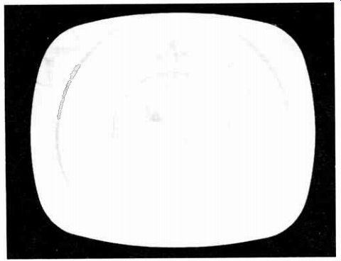
Fig. 6-8. Test pattern showing effect when brightness control is set too high.
Horizontal-Hold Control
The horizontal-hold control is an adjustment of the horizontal synchronization circuits. Misadjustment of this control will cause the picture to move either right or left, or, in extreme cases, it will cause black-and-white horizontal bars to appear on the screen, as shown in Fig. 6-9. This control should be adjusted until the picture appears, is centered, and there is no horizontal movement.
Vertical-Hold Control
When switching from a strong to a weaker station, sometimes it may be necessary to readjust the vertical-hold control. Misadjustment of this control will cause the picture to roll up or down, as shown in Fig. 6-10. This control should be adjusted so that there is no vertical movement in the picture.
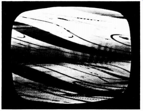
Fig. 6-9. Test pattern showing misadjusted horizontal-hold control. The more
the horizontal-hold control is misadjusted, the more diagonal bars appear;
as correct adjustment is approached, fewer bars appear.
STEP-BY-STEP TUNING PROCEDURE
In order to select a particular station and adjust the various controls for correct picture and sound reception, proceed as follows:
1. Turn the volume control about one-half turn clockwise; this supplies power to the receiver.
2. Turn the channel selector so that it indicates the number of the desired station channel.
3. Turn the fine-tuning control for best detail of the picture and good sound.
4. If necessary, adjust the horizontal- and/or vertical-hold controls to properly synchronize the picture.
5. Adjust the contrast and brightness controls to obtain the proper shading and overall brightness in the picture; that is, it should have good deep blacks, whites, and intermediate shades of gray.
6. Readjust the volume for the most pleasing reproduction.
After the receiver has been adjusted as indicated, the volume control should by used only to turn the receiver on or off between the desired programs unless some other station is to be tuned in.
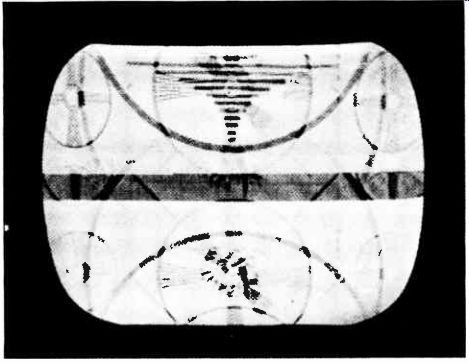
Fig. 6-10. Test pattern showing misadjusted vertical-hold control. As correct
adjustment is approached, the pattern moves slower and slower until it locks
in position.
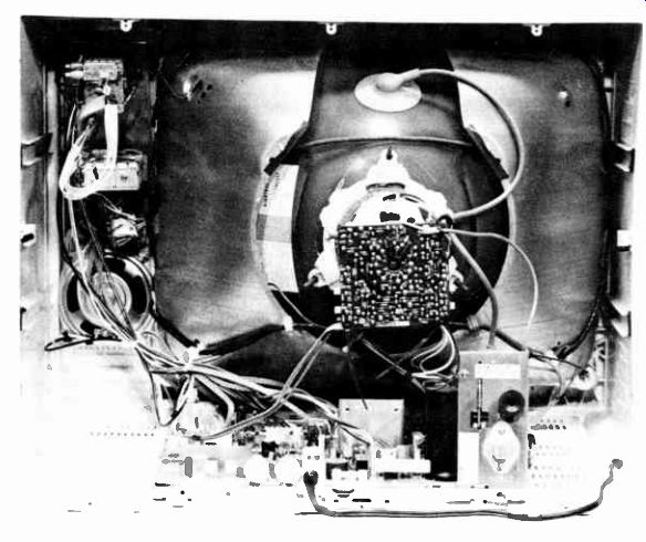
Fig. 6-11. Rear view of a television with the cover removed.
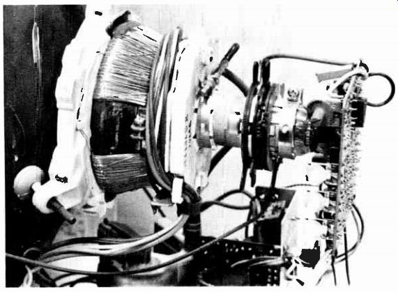
Fig. 6-12. Service controls mounted on the neck o the picture tube.
PRESET, OR SERVICE, ADJUSTMENT CONTROLS
The preset, or service, adjustments are factory adjusted for optimum performance; however, it is usually necessary to make some adjustments at the time of installation. The service adjustment controls usually consist of the following:
1. Focus control
2. Vertical size (height)
3. Vertical linearity
4. Horizontal size (width)
5. Horizontal linearity
6. AGC
Depending upon the design of the receiver, some of these controls may be located at the front or side of the cabinet, whereas others may be located in the rear of the chassis. In addition, all the controls may not be included in all receiver designs, and other receivers may include controls not listed in the foregoing. Three arrangements for service controls are shown in Figs. 6-11 and 6-12. In other receivers, other arrangements will be employed.
Focus Adjustment
It the various elements in the picture are not sharp and crisp but appear blurred and printing is difficult to read, the focus should be adjusted Proper focus is obtained by looking at the horizontal scanning lines that make up the picture and adjusting for minimum width of the lines.
Various means are employed for adjusting the focus. In some receivers, a control on the rear panel is rotated until the best focus is obtained. In others, a screwdriver adjustment or flexible shaft extending from the focus unit around the neck of the tube is adjusted until proper focus is obtained. In still another arrangement, a terminal strip that provides a choice of three or four different voltages is located on the chassis. A lead from the picture-tube socket is connected to the terminal that gives the best focus. Usually a clip arrangement is provided to facilitate this connection. The result of an improperly adjusted focus control is shown in Fig. 6-13.
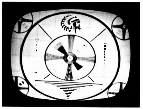
Fig. 6-13. Test pattern showing effect of misadjusted focus control.
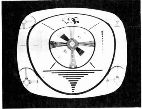
Fig. 6-14. Test pattern showing effect of misadjusted vertical-linearity control.
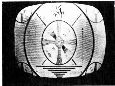
Fig. 6-15. Test pattern showing effect of misadjusted height control.
Height and Vertical-Linearity Control
These controls should both be adjusted at the same time, preferably while a test is being transmitted. The linearity control affects the upper portion of the picture (Fig. 6-14), while the height (size) control affects primarily the lower portion but also the overall picture (Fig. 6-15). Adjust both controls simultaneously until the test pattern is symmetrical and fills the entire screen vertically. Readjust the vertical-hold control if necessary.
Width Control
Control of picture size in the horizontal direction is accomplished by means of the width control. If the picture does not fill the screen horizontally (Fig. 6-16), adjust the control until the picture fills the screen. If an abnormally low line voltage makes it difficult to obtain sufficient picture width using the width control, changing the horizontal-drive control (if present) may prove helpful. Note that although the width control may be an ordinary variable-resistance control, it is often the slug in a variable inductance. In other receivers, a plastic sleeve with a piece of copper embedded in it is inserted between the neck of the picture tube and the deflection yoke. The width is varied by sliding the sleeve in and out on the neck. In still other receivers, no width control is included.
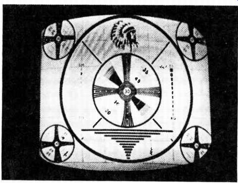
Fig. 6-16. Test pattern showing effect of misadjusted width control.
Horizontal Linearity Control
This control should be adjusted for best possible horizontal linearity. In the event that proper horizontal linearity (Fig. 6-17) cannot be obtained by adjusting this control, then change the setting of the horizontal-drive and/or-width control. Like the width control, the linearity control is most often the slug of a variable inductance. In other systems, no control, as such, is included, but linearity is adjusted by changing the position of small magnets that extend from the neck of the picture tube. In still other receivers, no provisions are included for adjusting the linearity.
Horizontal-Drive Control
Misadjustment of the horizontal-drive control (not included in many chassis) results in the symptoms shown in Fig. 6-18. If white vertical bars, black beaded lines, or foldover appears in the picture, the drive control should be adjusted.
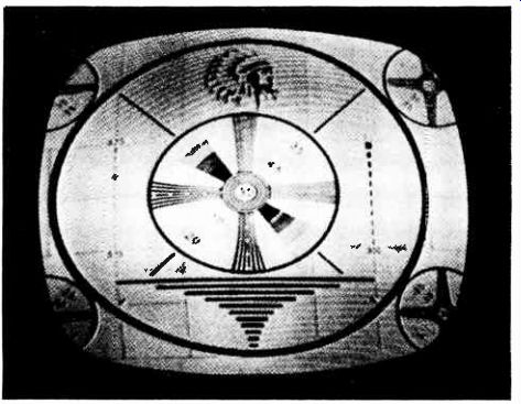
Fig. 6-17. Test pattern showing effect of misadjusted horizontal-linearity
control.
AGC Control
Many receivers contain some type of AGC control. Many names are used for these controls, but all perform essentially the same function. In some receivers, a variable-resistance control may be employed. When the AGC control is misadjusted, the symptoms can range from a weak, snowy picture to an over loaded one. (In an overloaded picture, everything is much darker than normal, and partial or complete loss of horizontal or vertical sync may occur. Often, these symptoms are accompanied by a buzz in the sound.) The AGC control should be set to produce the best picture quality. Correct setting may change with picture strength.
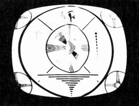
Fig. 6-18. Test pattern showing effect of misadjusted horizontal-drive control.
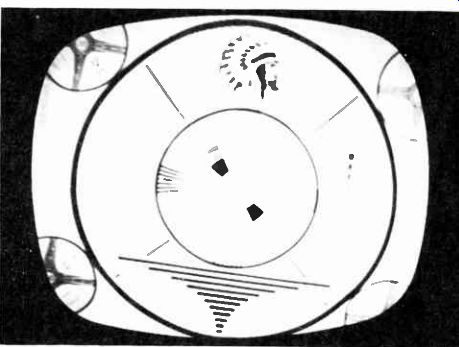
Fig. 6-19. Test pattern showing effect of misadjusted deflection yoke.
Tilted Raster
A tilted raster condition (Fig. 6-19) makes the test pattern or picture appear in a slightly tilted position. The remedy consists of rotating the yoke until the situation is corrected. In some receivers (Fig. 6-20) a thumbscrew must be loosened before the deflection yoke can be rotated. This locking screw should be re-tightened after the operation. In others (Fig. 6-21) no locking screw is employed.
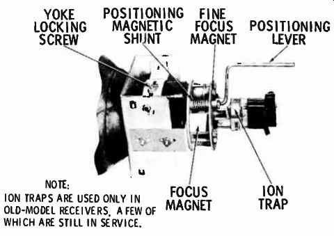
Fig. 6-20. Neck of a picture tube in a TV receiver that employs a deflection
yoke with a retaining screw and a permanent-magnet-focus device with positioning
lever.
Centering
Figure 6-22 shows a test pattern with the horizontal centering misadjusted. A similar condition will exist when the vertical centering is misadjusted except, of course, the blank space will be at the top or bottom of the screen (Fig. 6-23). The centering adjustments will be located on the rear panel of the chassis or on the neck of the picture tube. In some early receivers, two control-labeled vertical centering and horizontal centering- were located on the rear of the chassis. These controls are rotated until the picture is properly centered. (Note: The width and height controls may need readjustment after the picture is properly centered.) In another method, centering is accomplished by moving a positioning lever attached to a magnetic shunt in the focus coil (Fig. 6-20). This lever is used for both horizontal and vertical adjustments. Still another method employs a tab that extends from the top of the focus coil and is secured with a thumbscrew.
To adjust this type of arrangement, loosen the thumbscrew and move the tab up and down and to the right and left until the picture is properly centered.
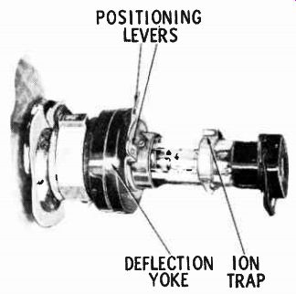
Fig. 6-21. Neck of a picture tube in a TV receiver that employs an unsecured
deflection yoke and two magnetized for a centering device.
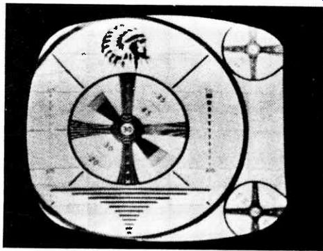
Fig. 6-22. Test pattern showing incorrect horizontal centering.
In most popular centering arrangements for modern TV receivers, two magnetized rings are included on the neck of the tube, as shown in Fig. 6-21. Attached to these rings are tabs which are rotated until the picture is properly centered.
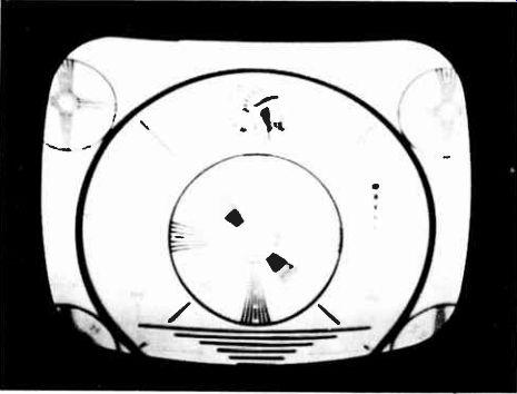
Fig. 6-23. Test pattern showing incorrect vertical centering.
In each of the centering methods employing adjustments on the neck of the tube, there is a certain amount of interaction between the adjustments. Work slowly and carefully until you "get the feel" of the adjustment. Extreme care should be employed to be sure that you do not place undue strain on the neck of the picture tube.
Eliminating Semicircular Shadows
Semicircular shadows (Fig. 6-24) are caused by the electron stream striking the neck of the tube. If the condition cannot be corrected by adjusting the centering controls, it can usually be corrected by applying one or a combination of the following procedures:
1. Make sure that the deflection yoke is positioned as far for ward as possible.
2. Reposition the focus coil by readjusting the holding nuts to shift the coil forward.
3. In the event the neck shadow cannot be eliminated by the foregoing procedure, raise or lower the entire yoke and focus-coil assembly so that the focus coil can be repositioned vertically with respect to the tube neck.
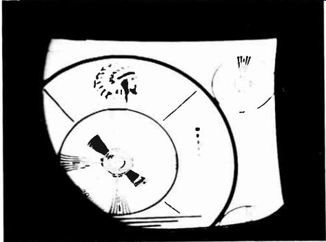
Fig. 6-24. Test pattern showing neck shadow caused by an improperly adjusted
centering control.
SUMMARY
The proper placement of a television depends on many factors, such as room layout, size of rooms, lighting arrangements, power outlets, and antenna lead-in. In choosing a location for the TV receiver, remember to keep direct sunlight from windows from falling on the face of the screen. Naturally, heat is always a problem, and so the cabinet should never be set directly against the wall or close to a heat vent or radiator, etc.; the effect of the heat will impair its operation or even damage the receiver.
Every television receiver contains several controls that are varied to obtain proper picture contrast and sound transmission.
Some adjustments must be varied more often than others; hence, manufacturers place some controls on the front, sides, top, or other convenient place on the cabinet where they are readily accessible. These controls are called operator controls.
Other controls, called service adjustments, are located on rear panels of the chassis, the chassis itself, or, in some cases, the neck of the picture tube. Most of these controls are needed as adjustments during normal reception. These controls, or adjustments, generally include focus, vertical height (size), vertical linearity, horizontal width (size), horizontal linearity, and AGC.
QUIZ
1. What is the difference between operator controls and ser vice adjustments?
2. What adjustments are considered to be operator controls?
3. What is meant by resolution?
4. What is meant by aspect ratio?
5. What is the purpose of the deflection-yoke adjustments?