17. General Design Considerations
During the past three decades, a range of circuit design techniques has evolved to allow the construction of highly linear gain stages based on bipolar transistors whose input characteristics are, in themselves, very nonlinear. These techniques have also allowed substantial improvements in possible stage gain and have led to greatly improved performance from linear, but low gain, field-effect devices.
These techniques are used in both discrete component designs and in their monolithic integrated circuit equivalents, although, in general, the circuit designs employed in linear ICs are considerably more complex than those used in discrete component layouts.
This is partly dictated by economic considerations, partly by the requirements of reliability, and partly because of the nature of IC design.
The first two of these factors arise because both the manufacturing costs and the probability of failure in a discrete component design are directly proportional to the number of components used, so the fewer the better, whereas in an IC, both the reliability and the expense of manufacture are affected only minimally by the number of circuit elements employed.
In the manufacture of ICs, as indicated earlier, some of the components that must be employed are much worse than their discrete design equivalents. This has led the IC designer to employ fairly elaborate circuit structures, either to avoid the need to use a poor-quality component in a critical position or to compensate for its shortcomings.
Nevertheless, the ingenuity of the designers and the competitive pressures of the market- place have resulted in systems having a very high performance, usually limited only by their inability to accept differential supply line potentials in excess of 36 V unless nonstandard diffusion processes are employed.
For circuitry requiring higher output or input voltage swings than allowed by small signal ICs, the discrete component circuit layout is, at the moment, unchallenged. However, as every designer knows, it is a difficult matter to translate a design that is satisfactory at a low working voltage design into an equally good higher voltage system.
This is because:
-- increased applied potentials produce higher thermal dissipations in the components for the same operating currents;
-- device performance tends to deteriorate at higher interelectrode potentials and higher output voltage excursions; and,
-- available high/voltage transistors tend to be more restricted in variety and less good in performance than lower voltage types.
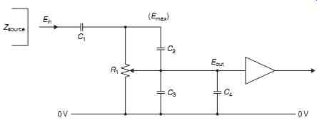
FIG. 50: Standard gain control circuit.
18 Controls
These fall into a variety of categories:
-- gain controls needed to adjust the signal level between source and power amplifier stages;
-- tone controls used to modify the tonal characteristics of the signal chain ; and,
-- filters employed to remove unwanted parts of the incoming signal, and those adjustments used to alter the quality of the audio presentation, such as stereo channel balance or channel separation controls.
18.1 Gain Controls
These are the simplest in basic form and are often just a resistive potentiometer voltage divider of the type shown in FIG. 50 . Although simple, this component can generate a variety of problems. Of these, the first is due to the value chosen for R1 . Unless this is infinitely high, it will attenuate the maximum signal voltage (Emax ) obtainable from the source, in the ratio …
where Zsource is the output impedance of the driving circuit. This factor favors the use of a high value for R1 to avoid loss of input signal.
However, the following amplifier stage may have specific input impedance requirements and is unlikely to operate satisfactorily unless the output impedance of the gain control circuit is fairly low. This will vary according to the setting of the control, between zero and a value, at the maximum gain setting of the control, due to the parallel impedances of the source and gain control.
The output impedance at intermediate positions of the control varies as the effective source impedance and the impedance to the 0-V line are altered. However, in general, these factors would encourage the use of a low value for R1 .
An additional and common problem arises because the perceived volume level associated with a given sound pressure (power) level has a logarithmic characteristic. This means that the gain control potentiometer, R1 , must have a resistance value that has a logarithmic, rather than linear, relationship with the angular rotation of the potentiometer shaft.
18.1.1 Potentiometer Law
Since the most common types of control potentiometer employ a resistive composition material to form the potentiometer track, it is a difficult matter to ensure that the grading of conductivity within this material will follow an accurate logarithmic law.
On a single channel this error in the relationship between signal loudness and spindle rotation may be relatively unimportant. In a stereo system, having two ganged gain control spindles, intended to control the loudness of the two channels simultaneously, errors in following the required resistance law, existing between the two potentiometer sections, will cause a shift in the apparent location of the stereo image as the gain control is adjusted, which can be very annoying.
In high-quality equipment, this problem is sometimes avoided by replacing R1 by a precision resistor chain ( Ra - Rz ), as shown in FIG. 51 , in which the junctions between these resistors are connected to tapping points on a high-quality multiposition switch.
By this means, if a large enough number of switch tap positions is available, and this implies at least a 20-way switch to give a gentle gradation of sound level, a very close approximation to the required logarithmic law can be obtained, and two such channel controls could be ganged without unwanted errors in the differential output level.
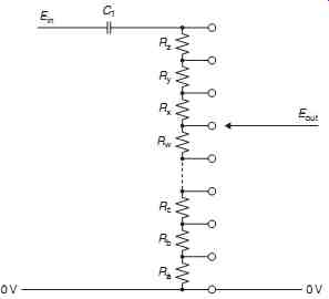
FIG. 51: Improved gain control using a multi-pole switch.
18.1.2 Circuit Capacitances
A further practical problem, illustrated in FIG. 50 , is associated with circuit capacitances. First, it is essential to ensure that there is no standing DC potential across R1 in normal operation, as this will cause an unwanted noise in the operation of the control. This imposes the need for a protective input capacitor, C1 , which will cause a loss of low-frequency signal components, with a _ 3-dB LF turnover point at the frequency at which the impedance of Cm is equal to the sum of the source and gain control impedances. C1 should therefore be of an adequate value.
Additionally, there are the effects of the stray capacitances, C2 and C3 , associated with the potentiometer construction, and the amplifier input and wiring capacitances, C4 .
The effect of these is to modify the frequency response of the system, at the HF end, as a result of signal currents passing through these capacitances. The choice of a low value for R1 is desirable to minimize this problem.
The use of the gain control to operate an on/off switch, which is fairly common in low cost equipment, can lead to additional problems, especially with high resistance value gain control potentiometers, in respect to AC mains " hum " pick up. It also leads to a more rapid rate of wear of the gain control in that it is rotated at least twice whenever the equipment is used.
18.2 Tone Controls
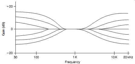
FIG. 52: Bass and treble lift/cut tone control.
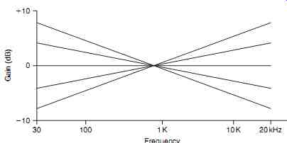
FIG. 53: Slope control.
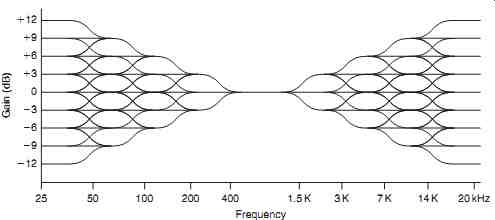
FIG. 54: Clapham junction type of tone control.
These exist in the various forms shown in FIGs. 52- 56 , respectively, described as standard (bass and treble lift or cut), slope control, Clapham junction, parametric, and graphic equalizer types. The effect these will have on the frequency response of the equipment is shown in the drawings, and their purpose is to help remedy shortcomings in the source program material, the receiver or transducer, or in the loudspeaker and listening room combination.
To the hi-fi purist, all such modifications to the input signal tend to be regarded with distaste and are therefore omitted from some hi-fi equipment. However, they can be useful and make valuable additions to the audio equipment, if used with care.
18.2.1 Standard Tone Control Systems
These are either of the passive type, of which a typical circuit layout is shown in FIG. 57 , or are constructed as part of the negative feedback loop around a gain block using the general design due to Baxandall. A typical circuit layout for this kind of design is shown in FIG. 58 .
It is claimed that the passive layout has an advantage in quality over the active (feedback network) type of control in that the passive network merely contains resistors and capacitors and is therefore free from any possibility of introduced distortion, whereas the "active" network requires an internal gain block, which is not automatically above suspicion.
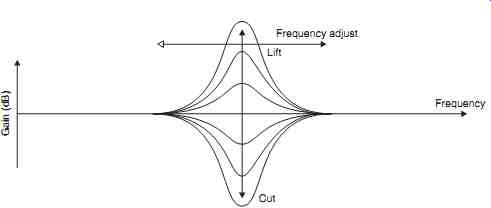
FIG. 55: Parametric equalizer control.
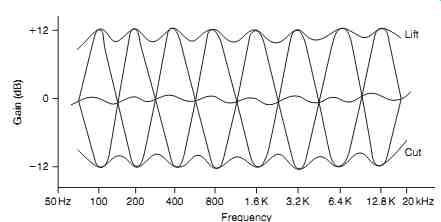
FIG. 56: Graphic equalizer response characteristics.
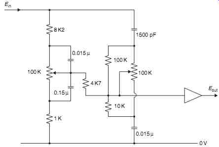
FIG. 57: Circuit layout of passive tone control.
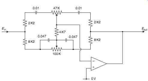
FIG. 58: Negative feedback type tone control circuit.
In reality, however, any passive network must introduce an attenuation, in its flat response form, which is equal to the degree of boost sought at the maximum " lift " position, and some external gain block must therefore be added to compensate for this gain loss.
This added gain block is just as prone to introduce distortion as that in an active network, with the added disadvantage that it must provide a gain equal to that of the flat-response network attenuation, whereas the active system gain block will typically have a gain of unity in the flat response mode, with a consequently lower distortion level.
As a final point, it should be remembered that any treble lift circuit will cause an increase in harmonic distortion, simply because it increases the gain at the frequencies associated with harmonics, in comparison with that at the frequency of the fundamental.
The verdict of the amplifier designers appears to be substantially in favor of the Baxandall system in that this is the layout employed most commonly.
Both of these tone control systems-indeed this is true of all such circuitry-rely for their operation on the fact that the AC impedance of a capacitor will depend on the applied frequency, as defined by the equation:
…where j is the square root of - 1.
Commonly, in circuit calculations, the 2 pf group of terms is lumped together and represented by the Greek symbol ? .
The purpose of the j term, which appears as a " quadrature " element in the algebraic manipulations, is to permit the circuit calculations to take account of the 90° phase shift introduced by the capacitative element. (The same is also true of inductors within such a circuit, except that the phase shift will be in the opposite sense.) This is important in most circuits of this type.
The effect of the change in impedance of the capacitor on the output signal voltage from a simple RC network, of the kind shown in FIGs. 59(a) and 7.60(a) , is shown in
FIGs. 59(b) and 60(b) . If a further resistor, R2 , is added to the networks, the result is modified in the manner shown in FIGs. 61 and 62 . This type of structure, elaborated by the use of variable resistors to control the amount of lift or fall of output as a function of frequency, is the basis of the passive tone control circuitry of FIG. 57 .
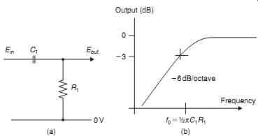
FIG. 59: Layout and frequency response of a simple bass-cut circuit (high
pass).
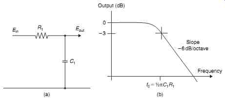
FIG. 60: Layout and frequency response of a simple treble-cut circuit (low
pass).
If such networks are connected across an inverting gain block, as shown in FIGs. 63(a) and 7.64(a) , the resultant frequency response will be shown in FIGs. 63(b)
and 7.64(b) , since the gain of such a negative feedback configuration will be ...assuming that the open-loop gain of the gain block is sufficiently high. This is the design basis of the Baxandall type of tone control, and a flat frequency response results when the impedance of the input and output limbs of such a feedback arrangement remains in equality as the frequency is varied.
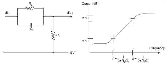
FIG. 61: Modified bass-cut (high-pass) RC circuit.
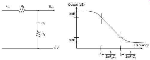
FIG. 62: A modified treble-cut (low-pass) RC circuit.
18.2.2 Slope Controls
This is the type of tone control employed by Quad in its type 44 preamplifier and operates by altering the relative balance of the LF and HF components of the audio signal, with reference to some specified midpoint frequency, as is shown in FIG. 53 . A typical circuit for this type of design is shown in FIG. 65 .
The philosophical justification for this approach is that it is unusual for any commercially produced program material to be significantly in error in its overall frequency characteristics, but the tonal preferences of the recording or broadcasting balance engineer may differ from those of the listener.
In such a case, he might consider that the signal, as presented, was somewhat overheavy, in respect to its bass, or alternatively, perhaps, that it was somewhat light or thin in tone, and an adjustment of the skew of the frequency response could correct this difference in tonal preference without significantly altering the signal in other respects.
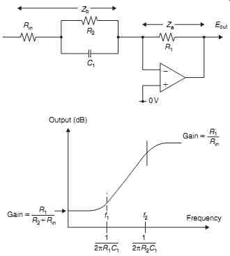
FIG. 63: Active RC treble-lift or bass-cut circuit.
18.2.3 The Clapham Junction Type
This type of tone control, whose possible response curves are shown in FIG. 54 , was introduced by the author to provide a more versatile type of tonal adjustment than that offered by the conventional standard systems for remedying specific peaks or troughs in the frequency response, without the penalties associated with the graphic equalizer type of control, described later.
In the Clapham junction type system, so named because of the similarity of the possible frequency response curves to that of railway lines, a group of push switches is arranged to allow one or more of a multiplicity of RC networks to be introduced into the feedback loop of a negative feedback type tone control system, as shown in FIG. 66 , to allow individual 3-dB frequency adjustments to be made, over a range of possible frequencies.
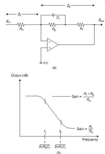
FIG. 64: Active RC treble-cut or bass-lift circuit.
By this means it is possible, by combining elements of frequency lift or cut, to choose from a variety of possible frequency response curves without losing the ability to attain a linear frequency response.
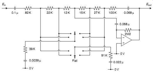
FIG. 65: The Quad tilt control.
18.2.4 Parametric Controls
This type of tone control, whose frequency response is shown in FIG. 55 , has elements of similarity to both the standard bass/treble lift/cut systems and the graphic equalizer arrangement in that while there is a choice of lift or cut in the frequency response, the actual frequency at which this occurs may be adjusted, up or down, in order to attain an optimal system frequency response.
A typical circuit layout is shown in FIG. 67
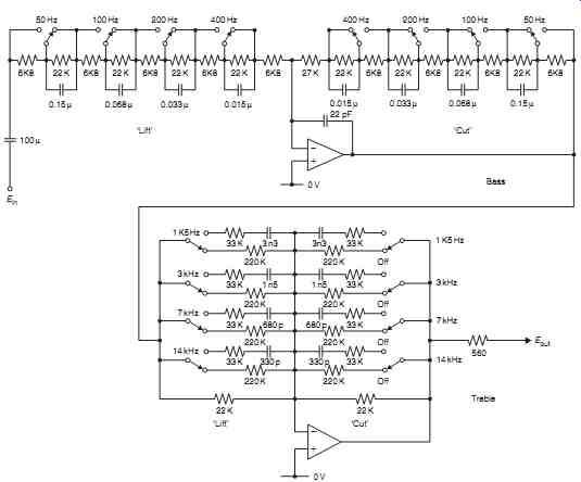
FIG. 66: Clapham junction tone control.
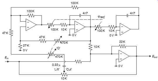
FIG. 67: Parametric equalizer circuit.
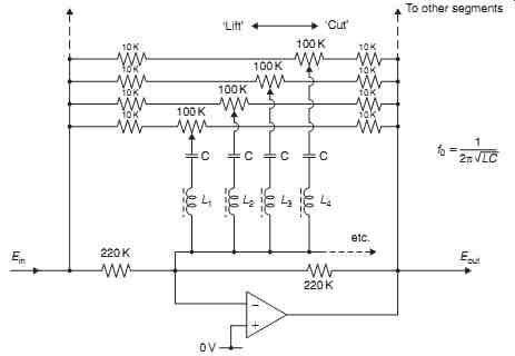
FIG. 68: Circuit layout for a graphic equalizer (only four sections shown).
18.2.5 The Graphic Equalizer System
The aim of this type of arrangement is to compensate fully for the inevitable peaks and troughs in the frequency response of the audio system, including those due to deficiencies in the loudspeakers or the listening room acoustics, by permitting the individual adjustment of the channel gain, within any one of a group of eight single-octave segments of the frequency band, typically covering the range from 80 Hz to 20 kHz, although 10 octave equalizers covering the whole audio range from 20 Hz to 20 kHz have been offered.
Because the ideal solution to this requirement-that of employing a group of parallel connected amplifiers, each of which is filtered so that it covers a single octave band of the frequency spectrum, whose individual gains could be adjusted separately-would be excessively expensive to implement, conventional practice is to make use of a series of LC-tuned circuits, connected within a feedback control system, as shown in FIG. 68 .
This gives the type of frequency response curve shown in FIG. 56 . As can be seen, there is no position of lift or cut, or combination of control settings, that will permit a flat frequency response because of the interaction, within the circuitry, between the adjacent octave segments of the pass band.
While such types of tone control are undoubtedly useful and can make significant improvements in the performance of otherwise unsatisfactory hi-fi systems, the inability to attain a flat frequency response when this is desired, even at the mid-position of the octave-band controls, has given such arrangements a very poor status in the eyes of the hi-fi fraternity. This unfavorable opinion has been reinforced by the less than optimal performance offered by inexpensive, add-on units whose engineering standards have reflected their low purchase price.
18.3 Channel Balance Controls
These are provided in any stereo system to equalize the gain in the left- and right-hand channels and to obtain a desired balance in the sound image. (In a quadraphonic system, four such channel gain controls will ideally be provided.) In general, there are only two options available for this purpose: those balance controls that allow one or the other of the two channels to be reduced to zero output level and those systems, usually based on differential adjustment of the amount of negative feedback across controlled stages, in which the relative adjustment of the gain, in one channel with reference to the other, may only be about 10 dB.
This is adequate for all balance correction purposes, but does not allow the complete extinction of either channel.
The first type of balance control is merely a gain control, of the type shown in FIG. 50 . A negative feedback type of control is shown in FIG. 69 .
18.4 Channel Separation Controls
While the closest reproduction, within the environment of the listener, of the sound stage of the original performance will be given by a certain specific degree of separation between signals within the ' L ' and ' R ' channels, it is found that shortcomings in the design of the reproducing and amplifying equipment tend universally to lessen the degree of channel separation rather than the reverse.
Some degree of enhancement of channel separation is therefore often of great value, and electronic circuits for this purpose are available, such as that, due to the author, shown in FIG. 70 .
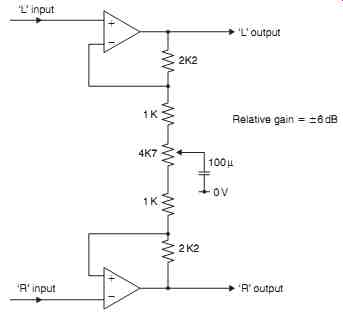
FIG. 69: Negative feedback type channel balance control.
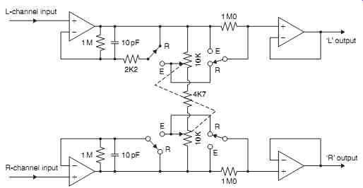
FIG. 70: Circuit for producing enhanced or reduced stereo channel separation.
There are also occasions when a deliberate reduction in the channel separation is advantageous, as, for example, in lessening " rumble " effects due to the vertical motion of a poorly engineered record turntable or in lessening the hiss component of a stereo FM broadcast. While this is also provided by the circuit of FIG. 70 , a much less elaborate arrangement, as shown in FIG. 71 , will suffice for this purpose.
A further, and interesting, approach is that offered by Blumlein, who found that an increase or reduction in the channel separation of a stereo signal was given by adjusting the relative magnitudes of the ' L _ R ' and ' L _ R ' signals in a stereo matrix, before these were added or subtracted to give the ' 2L ' and ' 2R ' components.
An electronic circuit for this purpose is shown in FIG. 72 .
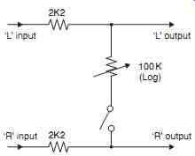
FIG. 71: Simple stereo channel blend control.
18.5 Filters
While various kinds of filter circuits play a very large part in the studio equipment employed to generate the program material, both as radio broadcasts and as recordings on disc or tape, the only types of filters normally offered to the user are those designed to attenuate very low frequencies, below, say, 50 Hz and generally described as " rumble "filters, or those operating in the region above a few kHz, and generally described as " scratch " or " whistle " filters.
Three such filter circuits are shown in FIG. 73 . Of these, the first two are fixed frequency active filter configurations employing a bootstrap type circuit for use, respectively, in high-pass (rumble) and low-pass (hiss) applications, and the third is an inductor-capacitor passive circuit layout, which allows adjustment of the HF turnover frequency by variation of the capacitor value.
Such frequency adjustments are, of course, also possible with active filter systems, but require the simultaneous switching of a larger number of components. For such filters to be effective in their intended application, the slope of the response curve, as defined as the change in the rate of attenuation as a function of frequency, is normally chosen to be high-at least 20 dB/octave-as shown in FIG. 74 , and, in the case of the filters operating in the treble region, a choice of operating frequencies is often required, as is also, occasionally, the possibility of altering the attenuation rate.
This is of importance, as rates of attenuation in excess of 6 dB/octave lead to some degree of coloration of the reproduced sound, and the greater the attenuation rate, the more noticeable this coloration becomes. This problem becomes less important as the turnover frequency approaches the limits of the range of human hearing, but very steep rates of attenuation produce distortions in transient waveforms whose major frequency components are much lower than notional cut-off frequency.
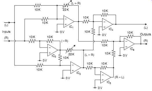
FIG. 72: Channel separation or blending using matrix addition or subtraction.
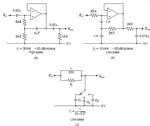
FIG. 73: Steep-cut filter circuits.
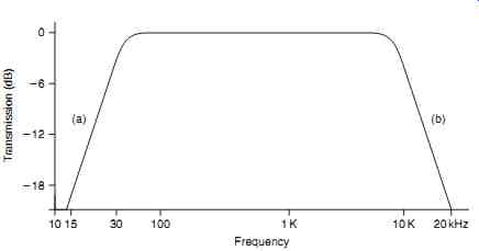
FIG. 74: Characteristics of circuits of FIGs. 73(a) and 73(b) .
It is, perhaps, significant in this context that recent improvements in compact disc players have all been concerned with an increase in the sampling rate, from 44.1 kHz to 88.2 kHz or 176.4 kHz, to allow more gentle filter attenuation rates beyond the 20-kHz audio pass band than that provided by the original 21-kHz " brick wall " filter.
The opinion of the audiophiles seems to be unanimous that such CD players, in which the recorded signal is two or four times " oversampled, " which allows much more gentle " anti-aliasing " filter slopes, have a much preferable HF response and also have a more natural, and less prominent, high-frequency characteristic than that associated with some earlier designs.
== == ==