by LEONARD FELDMAN
The state-of-the-art of "simultaneous 4-channel stereo" from a single stereo FM station
THE COMING OF 4-CHANNEL SOUND in the home has been discussed more than once in recent issues of Audio. Suddenly, a long-dormant interest in multi-channel sonic reproduction seems to be coming from all segments of the audio and high-fidelity industry.
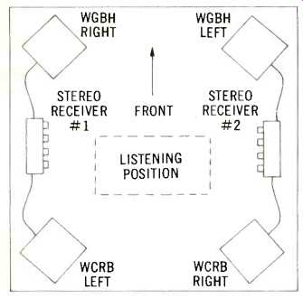
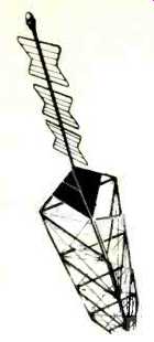
Fig. 1--Suggested speaker arrangement for the Boston Symphony 4-channel
broadcasts.
The first practical program source to supply material for 4-channel listening was, of course, pre-recorded tape. Computer technology has, for many years, been utilizing 8, 12, 24, and even more channels of information on a single reel of tape. It is therefore rather surprising that more than three decades of time have elapsed since we were treated to the marvelous aural experience of Walt Disney's Fantasia. Those of us who are old enough to remember our first reaction to that version of "total surround stereo" have perhaps wondered over the years why such an all-encompassing sonic experience has been denied us. Apparently our patience is about to be rewarded.
If and when the history of 4-channel sound is ever written in the future, several individuals and firms will be mentioned as having been responsible for this new interest in 4-channel sound. There will be those, too, who will skeptically maintain that this new approach to home music listening is nothing more than a sales gimmick thought up by greedy manufacturers intent upon selling "another pair of everything." These skeptics simply haven't heard total surround stereo.
To hear it is to realize what has already become a cliche in this brand-new technique: "the difference between 4-channel and conventional stereo sound is perhaps greater than between 2-channel stereo as we know it and monophonic reproduction." Vanguard Recording Company and Acoustic Research, Inc., must be credited with stimulating the initial new interest in this field. In cooperation with FM radio stations WGBH and WCRB in the Boston area, these two firms have been sponsoring a series of live symphonic concerts utilizing the regular subscription series of the famed Boston Symphony Orchestra.
Figure 1 illustrates the layout of the four loudspeakers and the two FM stereo receivers required in a home listening situation. Two things are apparent when you examine this figure.
A great deal of equipment is needed and the distribution of 4-channel information is very odd. When we first saw this diagram we questioned the wisdom of putting the front-left and rear-left on one FM station while the other station carried front-right and rear-right information. What sort of a lopsided program would the listener equipped with only one stereo receiver hear?
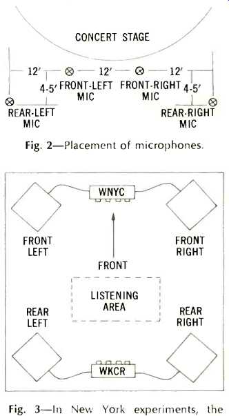
Fig. 2--Placement of microphones.
Fig. 3--In New York experiments, the "primary" stereo channels are carried by WNYC-FM, while WKCR carries the rear right and rear-left channels.
Recently we had an opportunity to discuss this problem with Mr. Richard Kaye, one of the directors of participating station WCRB. Once he explained the microphone placement used in the concert hall and diagramed in Fig. 2, we realized the nature of the problem. Had WCRB elected to broadcast front-left and front-right and relegated the rear-left and rear-right to cooperating station WGBH, can you imagine the phone calls that WGBH would have received from its irate listeners? The microphone placement shown in Fig. 2 was an attempt to offer all things to all listeners. While the left two microphones were designated as left-front and left-rear, the left-rear microphone was, in fact, considerably further to the left than the left-front and only four or five feet behind it. The same arrangement applied to the two right microphones. In this way, it was hoped that a listener equipped with a single stereo receiver would still experience a fair amount of separation, while the hearty souls able to set up dual stereophonic systems would experience some of the ambient qualities of the symphony hall--the avowed purpose of the 4-channel experiment in this instance. Listeners have been most enthusiastic, but we wonder if this enthusiasm is prompted by the novelty of the 4-channel listening experience rather than by its state of perfection.
Beginning October 26, 1969, New York City audiophiles were able to duplicate the experience of the Boston listeners. Harry Maynard, host of the popular "Men of Hi-Fi" program broadcast weekly over WNYC, has crusaded for 4-channel stereo. With the assistance of members of the New York Audio Society who helped to publicize the broadcast and the cooperation of radio stations WNYC-FM and WKCR, (WNYC-FM is the municipally run broadcasting facility and WKCR is operated by Columbia University), 4-channel stereo broadcasting is a regular event in the New York City area. Unlike the Boston experiment, however, the channel arrangement is as shown in Fig. 3.
Admittedly, WKCR must be making a supreme sacrifice in agreeing to carry just the rear-right and rear-left channels. As of this writing we don't know what the reaction will be from listeners attempting to tune in to WKCR on Sunday night at 10 p.m. utilizing either a single monophonic FM receiver or even a conventional 2-ehannel stereophonic receiver. Those of us involved in the New York experiment felt, however, that this microphone arrangement will provide greater impact for 4-channel listeners than would be possible with the Boston arrangement. It is apparent, I think, that both arrangements have serious limitations. We are reminded of similar compromises that took place in the mid-1950s when early attempts at stereophonic broadcasting were confined to AM/FM combinations. True, the problems inherent in those early experiments were even greater, since the quality of the AM channel was so inferior with respect to noise and frequency response. Although the current experiments at least involve all-FM transmission, there do exist somewhat more subtle problems, such as: phase relationships between the cooperating stations, distances from each transmitter to a given receiver, compounded multipath effects, etc.
As was true in the 1950s, a better way will have to be found. William S. Halstead, a noted pioneer in the field of multiplex FM (and one of the many system proponents for stereo FM in the late 1950s) , and myself, have proposed at least one solution to the problem. Before describing our proposal, I would like to make it clear that this is by no means the only method possible. When 2-channel stereo FM was being considered by the FCC, some 17 systems were proposed before the presently adopted system was approved. We have no doubt that others will come forward now as well. In any event, the system we are proposing does work, permits a single FM station to broadcast four distinct channels of information simultaneously and (subject to certain qualifications which will be discussed in a moment) is compatible with the requirements of effective 4-channel musical reproduction as we presently understand them.
Fig. 4--Presently authorized modulation and frequency distribution for stereo
FM plus SCA broadcasting. (Only one half of spectrum is shown-other
half is mirror image to left of the "0" or carrier-frequency line.)
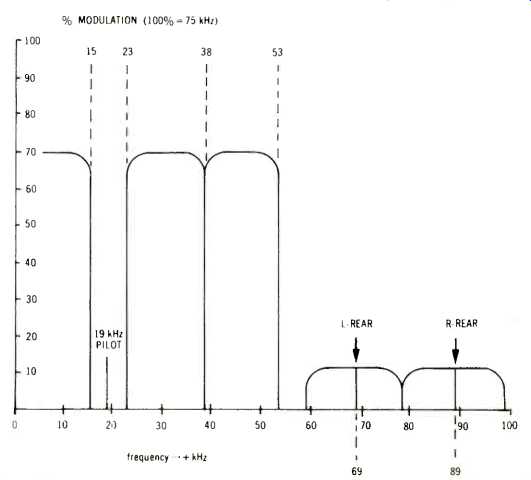
Fig. 5--Proposal for 4-channel FM multiplex broadcasting system, again showing
only one half of the entire spectrum.
Figure 4 shows presently approved spectrum distribution of a single FM channel engaged in stereo and SCA (background music, etc.) transmission.
Main-channel material occupies the range from 50 to 15,000 Hz. The stereo pilot subcarrier can be seen at 19,000 Hz, modulating the main carrier approximately 10 percent of the total. Stereophonic (L-R) information is contained in the range from 23,000 to 53,000 Hz. Finally, the SCA subchannel is located at a nominal frequency of 67,000 Hz and since it is an FM subcarrier, is seen to occupy the total range from 59 kHz to 75 kHz. The presence of the private-subscriber SCA subchannel necessitates a reduction in deviation of the main and stereo subchannels to a maximum of 80 percent. Thus, total deviation consists of 80 percent main and stereo subchannel, 10 percent pilot carrier and 10 percent SCA. Figure 5 illustrates the new spectral distribution proposed by Mr. Halstead and myself. All we have done is to add a second FM subcarrier at a frequency of 89 kHz (or thereabouts), shift the previously used SCA sub carrier to approximately 69 kHz, and back off the main and stereo subchannels an additional 10 percent so as not to exceed 100 percent modulation for the total composite signal. In terms of s/n it is interesting to note that our two "rear" subchannels (for we intend to use them for rear-left and rear-right information) are expected to be as good or possibly better than the presently used stereo subcarrier sidebands. This is so because the presently used L-R side bands are AM in nature whereas our proposed subchannels will be modulated in an FM mode.
What about frequency response for our two additional channels? Our early experiments indicate that it will be possible to broadcast frequencies as high as 10,000 Hz. We realize that the purists will scream and call this "lo-fi." To evaluate the adequacy (or inadequacy) of these parameters accurately, we must examine just what it is we're trying to accomplish with the addition of the third and fourth channels. If we are trying to duplicate more realistically the reverberant effects experienced in the live concert hall, there is sufficient evidence on hand to justify this modest frequency limitation imposed upon the extra channels, since their function is that of reinforcement and not that of providing primary musical information.
If,, on the other hand, the many popular musical forms on the scene plan to use the four channels for new creative effects (such as putting each member of a four-piece combo in his own corner), then it might be argued that all four channels must be equal in fidelity.
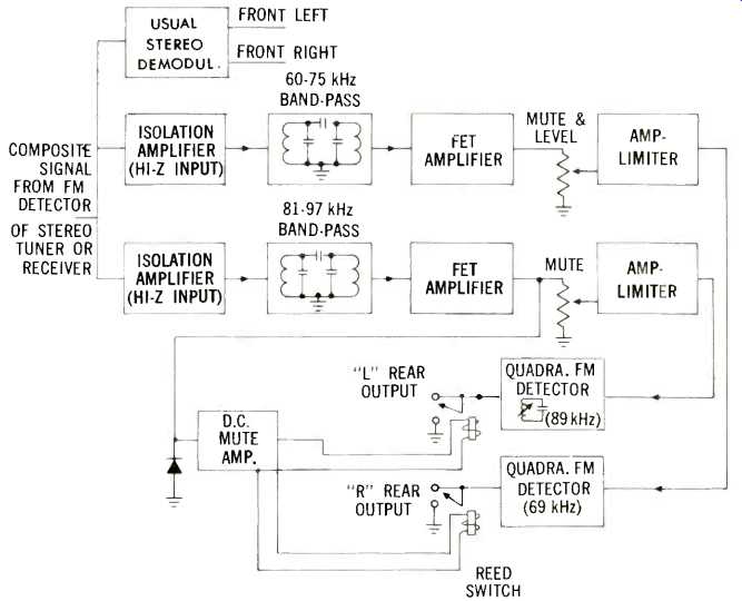
Fig. 6--Block diagram of 4-channel stereo FM adapter used to recover the
3rd and 4th channels.
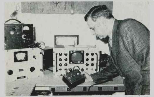
Fig. 7--The author about to measure performance of the first decoder designed
to work with the Halstead 4-channel stereo FM broadcasting system.
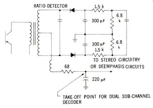
Fig. 8--Typical ratio-detector circuit, showing connection point for "3rd-&-4th-channel" decoder.
It is our contention that unless the recording session is "gimmicked" to the extent of recording these four instrumentalists in totally separate studios (a trick resorted to very often in the early days of stereo) , primary spatial information is sensed from fundamental tones rather than from harmonics or overtones. If this is so, then limitation in frequency response of the third and fourth channels will not perceptibly degrade the listen ability of the end product.
Currently, radio station WNYC-FM has requested permission from the FCC to transmit this system on an experimental basis. If, and when, the FCC grants permission, these questions and a great many technical feasibility questions will be answered in short order. Since such requests (Continued on page 78) for experimental transmission are usually granted sooner or later, it would be of interest to detail the nature of an adapter or decoder which might be needed to recover channels 3 and 4. Such an adapter has been built by the author. A block diagram of it is shown in Fig. 6, while its physical dimensions are shown in the photograph of Fig. 7. This adaptor could be connected easily to virtually any FM tuner or receiver presently in use.
Older tuners equipped with a so-called multiplex jack (built before the days of FM stereo) would not have to be tampered with at all, since the adaptor would plug right into this multiplex jack. Later vintage equipment could be adapted in minutes by connecting the proposed adaptor to the output of the detector (whether it be of a ratio-detector or discriminator type) of the tuner or receiver in question.
The typical point of connection, in the case of a ratio detector, is shown in Fig 8. Referring to Fig. 6, the entire composite signal derived at the detector output is fed to a pair of high input-impedance isolation amplifiers.
Each amplifier feeds a band-pass filter.
The upper filter passes the 69-kHz subchannel,, while the lower one passes the 89-kHz subchannel. Further amplification follows, as well as mute and level controls in each channel. In the case of the 89-kHz channel, the signal is fed to a muting amplifier. The output of the muting amplifier controls a pair of reed relays (or other solid-state switches) . In the absence of an 89-kHz signal, both outputs of the decoder are normally shorted so that no output is obtained. In the presence of an 89-kHz signal, the shorts are removed and L-rear and R-rear outputs are obtained.
While this muting function may seem like an unnecessary embellishment (after all, one could turn down the related volume controls on the amplifiers in the absence of 4-channel transmission) , it has been incorporated specifically to protect SCA (background music) operators from "piracy." You will recall that SCA operations generally employ a subcarrier of 67 kHz which is very close in frequency to our proposed third channel at 69 kHz. By having the decoder outputs "turned on" only in the presence of the upper (89-kHz) subchannel, inadvertent reception of background music will not occur when the tuner is tuned to a station engaged in that service.
--------------------
FOR "DOUBTING THOMASES"
The proposal described herein for 4-channel broadcasting from a single FM station may cause some concern over possible excessive spectral distribution in the FM channel. There is a great deal of misconception concerning this matter. Many people suppose that because total permissible deviation is limited to ±75 kHz and because channel bandwidth is nominally 150 kHz, no energy is permitted beyond 75 kHz from center frequency.
This is not true! The FCC permits energy to fall as far as 240 kHz beyond center frequency providing that this energy is attenuated at least 25 dB. Furthermore, subcarriers such as proposed in the main article featured here utilize a deviation ratio no greater than 1, which means that only a single sideband above and below subcarrier center frequency is generated. Thus, if we modulate the 89-kHz subcarrier with a frequency of 8 kHz (audio) and cause the sub carrier to be deviated ±8 kHz, then sidebands will be generated only at 97 kHz and at 81 kHz. It should be remembered, too, that the injection of each of these subcarriers is only 10 percent of the total injection of 20 dB below the 100-per-cent reference to begin with.
To convince disbelievers of the foregoing, we assembled a formidable amount of test equipment in order to prove these points. Included were a Boonton Model 202-B FM/AM Generator, a Moseley SG-4T Subcarrier Generator, and a Model LA-17 Panoramic Analyzer made by Lavoie Laboratories, Inc. A Crosby SG-292 Stereo Composite Signal Generator served to provide the regular stereo composite signal.
Figure 1 serves to establish the horizontal scale of the Panoramic Analyzer display. In (A) we see an unmodulated r.f. carrier.
In (B) the carrier has been detuned by 240 kHz in one direction, whereas in (C) it has been detuned an equal amount in the other direction. Thus, the length of the entire scale, horizontally, is equivalent to 480 kHz.
In the photos of Fig. 2, the vertical amplitude sensitivity has merely been increased by 18 dB. This has been done because this particular Panoramic Analyzer's vertical scale is logarithmic and some of the minute energy bursts which we wish to show would have been invisible had the vertical scale been maintained at its previous sensitivity. Figure 2(A), therefore, is merely a repeat of the unmodulated r.f. carrier presented on this expanded scale.
In (B), an unmodulated 69-kHz subcarrier has been added at proper 10 percent (-20-dB) injection level. In (C), this subcarrier was modulated by 10-kHz audio at a deviation maximum of 10 kHz. Notice that no additional significant sidebands appear.
Figure 2(D) shows the introduction of the second subcarrier at 89 kHz, while (E) displays both subcarriers with modulation having been applied to each. Note again that no unexpected additional sidebands appear anywhere.
The next and final group of figures may come as a shock to many readers. Figure 3(A) shows what happens to spectral distribution when a left-only stereo signal is applied. Main carrier modulation audio frequency is 15 kHz.
Yes, there seems to be substantial energy content up to around 150 kHz on either side of center frequency. In (B), we have introduced our pair of subcarriers and even modulated each one with an 8-kHz audio tone, but they are all but lost in the high-amplitude spectral contributions on the still-present left-only signal.
In (C), we applied an L + R signal of 15 kHz + a 10-percent pilot signal + the two additional subcarriers as before. The L + R signal was allowed to deviate the main carrier ± 50 kHz.
Spectral distribution seems almost identical to that of (B). Next, in (D) we modulated the carrier by independent L and R signals of 10 kHz and 15 kHz, respectively. A 19-kHz pilot carrier is present also, as it was in the previous three figures. We have, however, removed our extra subcarriers and thereby can increase the remaining deviation to a full 100% (75 kHz). The only conclusion we can draw from this presentation (which actually seems to occupy more spectral distribution than any of the previous ones) is that present stereo broadcasting techniques, when full modulation is applied, actually occupy more bandwidth under certain conditions than our proposed 4-channel system would under any conditions. In other words, by backing off 20 percent in main and stereo subchannel modulation to accommodate the new pair of subcarriers, we are actually more than compensating for their addition.
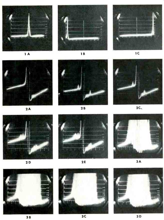
Fig. 1--(A)-Unmodulated carrier; (B)Unmodulated carrier shifted 240 kHz
downward to establish horizontal scale; (C)--Carrier shifted 240 kHz upward
to establish other end of horizontal scale.
Fig. 2--(A) Scale amplified so top of dB scale is now + 18 dB so components of smaller amplitude will be disclosed in later photos. (This scale used in all subsequent displays.) (B)-Carrier (unmodulated) with added 67-kHz subcarrier (unmodulated). (C)-Carrier (unmodulated plus 67 kHz subcarrier modulated by 10-kHz audio; deviation maximum of 8 kHz. (D)-Carrier (unmodulated) plus 67-kHz subcarrier (un modulated) plus 92-kHz subcarrier, each contributing 10% total deviation of main carrier. Main carrier has been monitored continuously to ensure that overall levels have not changed. (E)--Same as (D) except both 67and 92-kHz subcarriers are now being modulated by 8-kHz tones, with a deviation of 8 kHz.
Fig. 3--(A)-Carrier with an L-only signal applied; deviation is 45 kHz plus 10% contribution of 19-kHz pilot signal. Main carrier modulation frequency is 15 kHz. (B) Same as Fig. 1, except that two subcarriers have been added, each modulated 8 kHz by 8-kHz tones. (C)-Carrier with L-R signals at 15 kHz deviating a total of 50 kHz, plus 10% pilot signal, plus 10% each of two subcarriers, each of which is modulated by 8-kHz tones, as before; deviation is 8 kHz for subcarriers; (D)-Carrier modulated by 10and 15-kHz L and R signals, full stereo mode, plus 19-kHz pilot. No subcarriers applied. Total deviation of all components is 100% (75 kHz).
-------------------------------
(adapted from Audio magazine, Jan. 1970)
Also see:
Nine CD-4 Phono Cartridges Tested (Mar. 1974)
The Evolution of Four-Channel Equipment (Jul. 1973)
Why You Should Buy Four-Channel Now (Jul. 1973)
Quadraphonic Headphones (Jun. 1973)
Status: The CD-4 System (Jul. 1973)
= = = =