
by Curtiss R. Schafer
THE CORRECT APPLICATION of negative feedback in amplifiers has produced low-distortion, wide-range response that is pleasant to listen to. Until recently loudspeakers have not been able to incorporate inverse feedback.
The classic attempts to apply feedback to a loudspeaker are described by Olson'. They use either a secondary voice coil and magnetic structure (with the secondary coil rigidly coupled to the primary coil), or a microphone mounted in front of the speaker. In either case, the output of the microphone or secondary voice coil is connected to the input of the amplifier and out of phase with the input signal.
Another attempt by Holdaway and Denby in 1963 used negative velocity feedback, with the feedback voltage derived from a bridge in the voice coil circuit. The paper by Holdaway, and another by de Boer, present very interesting discussions of motional feedback. These attempts have not been entirely successful because of the loudspeaker loads 'and the modes of vibration of loudspeaker cones'. The typical cone moves as a piston over a relatively narrow frequency range and usually vibrates in at least eight different modes over the range from 50 to 10,000 Hz. These modal vibrations involve changing radial and annular sections of the cone, and thus, most of the time, the voice coil literally does not know what the cone is doing.
For these reasons, I decided on a purely acoustical form of negative feedback. Judging by the studies cited above, it seemed that both the speaker unit driven by the amplifier and the unit used as a microphone would have to possess very similar characteristics. This immediately suggested another idea: If two similar speakers were to be mounted back-to-back in a small enclosure and their voice coils phased so that both cones moved either in or our at any given instant, an internal pressure wave would be generated by one cone that would be 180% out of phase with that generated by the other cone. This would, in essence, be acoustical negative feedback and the magnitude of the feedback could be controlled by the resistive and reactive parameters of the air path between the two cones and also by the use of a T-pad to increase or diminish the signal supplied to one voice coil.
EDITOR'S NOTE:
A "push-pull" system was developed by the British G.E. Company in 1959. As might be expected only even harmonic distortion was significantly reduced. To test this concept, two 12-inch speakers were mounted in a 15 by 15 by 11 in. case as shown in Fig. 1. The interior was lined with two-inch pads of polyurethane foam wherever possible.
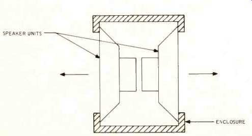
Fig. 1--Schematic diagram of the system.
After a half hour of listening to FM program material, it was apparent that the bass response went about an octave lower than that of the acoustic suspension speaker usually used and the transient response seemed better. These first impressions were confirmed by several hours of listening to records.
With this encouragement, I decided to design a wide-range speaker system that would embody my concept of acoustical negative feedback using the double speaker arrangement.
Several factors seemed important, first a wide frequency response (at least 20 to 20,000 Hz), since the widest range systems always sounded the best if modulation distortion is low; second, freedom from excessive resonant peaks and valleys; and third, enough acoustic power output for a large living room.
Other considerations were a reasonable physical size, the use of a low crossover frequency, only one crossover frequency since the dividing networks produce transient and phase distortions, and a high proportion of direct rather than reverberant sound.
I have always considered the highly reverberant acoustics of a large concert hall to be a necessary nuisance rather than a quality to be enjoyed. When reverberance predominates, it becomes for me a "mud factor." Recently I listened to a computer-designed loudspeaker system which used one unit to produce direct sound but eight units for reverberant sound. It was like listening to a symphony orchestra in a hall with bad acoustics; mind and ears are continually straining to bring some order out of confusion. Under such conditions, the matter of speaker transient response becomes irrelevant.
Several weeks were spent listening to speaker systems in dealer showrooms and attempts to get distortion vs. acoustic power data from the prominent speaker manufacturers. Finally the JBL LE-15A was selected as the woofer because it sounded best and because the manufacturer supplied a photograph showing the acoustic waveform produced by an input sine wave of 60 watts at 40 Hz, which indicated harmonic distortion of only about 5% under these conditions. The LE-15A has a long voice coil and can maintain excellent linearity at cone excursions up to ±1/2 inch from the center position (one inch peak to peak): Judged second best were the lower priced Wharfedale models W 15/RS and W 12/RS with ceramic magnets. Use of a ceramic magnet results in a "shallow" woofer design, which is preferred in this system because it permits the cones to be closer to each other. These models also have long voice coils; the W15/RS is linear for excursions of 3/4-in. peak-to-peak. (Wharfedale speaker units are not now available in the U.S. They can only be purchased in cabinets as completed systems. -Ed. )
An evaluation of treble units resulted in the purchase of a 511-B sectoral horn and a 802-D driver; a PM-7 wide range, double diaphragm unit of English manufacture, and a Wharfedale Super 10 RS/DD. The PM-7 is designed for horn loading but I felt that its use as a treble unit would not require much greater cone excursions than its use as the single driver in a wide range horn system.
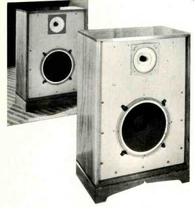
Fig. 2--The completed system, with a mirror showing the back side, which
is identical to the front and C, in Schafer feedback enclosure.
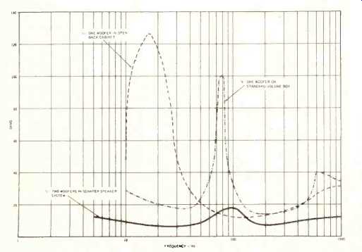
Fig. 3--Impedance curves. A, one woofer with open–backed enclosure; B, one
woofer with standard-volume enclosure.
When I took the sectoral horn out of its carton, I noticed that it rang like a bell whenever I rapped it with my knuckles. Thinking it may have been cracked in shipment, I returned it, and then found that the replacement did the same.
The bell-like resonances were quite audible on most program material. Since that time, I have found that most 500or 800-cycle sectoral horns have this fault. (This ringing is normally tamed when the horn is mounted but some engineers use heavy tape or "Mortite" to kill any resonances.-Ed)
The completed acoustic feedback speaker system is illustrated in Fig. 2. A mirror was placed to show the back of the cabinet (which is just like the front). The cabinet is 36 inches high, 27 wide, and 14 deep (front to back). The usual principles of good construction were followed: the top, bottom, sides, and compartment divider are made of two-inch-thick black oak; the speaker mounting panels are of one-inch particle board; all speakers are mounted from the outside of the panels. The interior of the enclosure is lined with pads of two-inch polyurethane foam. The whole structure is non-resonant, of course.
The two woofers were connected in parallel internally and phased with a flashlight cell so that both cones move outward simultaneously. The two treble units were connected in a similar fashion. The two pairs of leads were brought out to the dividing network. Several commercially available networks were tried, and I found that an Altec N-500! I gave the least phase shift in the crossover region of 500 cycles.
Our speaker system was then played through an FM tuner and one channel of a Dynaco Stereo 120 amplifier. From the very first moment it sounded good. It has all the qualities I had hoped for, excellent transient response, a tremendously solid bass, and good balance between bass and treble. As I had surmised the effects of negative acoustic feedback are most evident at the bass end of the range. The impedance curves to illustrate this are shown in Fig. 3.
After the cabinet had been completed, the foam pads were put in place and one woofer was installed. The other speaker panel was left off, so that the enclosure resembled an open-backed radio cabinet. The impedance of one woofer was measured under these conditions, with the results shown in Fig. 3a. The free air resonant frequency of this woofer is 18 Hz. The impedance was checked with the unit laid on its face on the standard-volume tee box used in designing ducted-port bass-reflex enclosures with the results shown in Fig. 3b.
With both panels and both woofers in place again, the impedance curve of Fig. 3c was obtained. (The crossover network was omitted for this measurement.) The nominal impedance of one woofer is 16 ohms, although the actual impedance at 200 HZ was found to be about 14 ohms. Thus the two woofers in parallel give an impedance of about 7 ohms at 200 Hz. In the double speaker system, this impedance shows a relatively small increase at the fundamental resonant frequency and does not show the usual rapid drop below this frequency.
The overall frequency response of the system has not been measured, but apparently ranges from about 10 Hz to a little over 20,000. Acoustic power output for the two woofers together is estimated at about 0.5 watt. This output is not adequate for a large concert hall or auditorium, unless more than one speaker system is used. However, for a small hall or large living room, its response is as good (15 Hz) as that of a hyperbolic horn 20 feet long with a mouth 5 by 7 feet. It has been A-B tested against several top-rated commercially available systems, and its superiority was apparent after a few minutes of listening.
Two other acoustic feedback speakers have been built. One uses a pair of Wharfedale W 15/RS woofers and a pair of Super 10/RS/DD treble units; the other uses W 12/RS woofers and Super 10/RS/DD tweeters. For each of these combinations, JBL LX5 dividing networks give the minimum phase shift. These systems were put into smaller cabinets and used less expensive speaker units, but the results, except for power-handling capability, are similar and almost as good.
I would like to have this article regarded as a description of what I believe to be a meritorious principle in loudspeaker design and as a statement of work in progress. My intent here is not to present a finished design; more work must be done. I would like to build dividing networks having better transient and phase characteristics and find better treble units. (The PM 7 range is up to 22,000 Hz, but the undamped edges of the whizzer cones produce dissonances at times: JBL LE -8T units probably would have been more suitable.) Also, both harmonic and modulation distortion measurements should be taken, as well as frequency response data, but I do not have the facilities to do this properly I hope that I may soon have the opportunity to work on this design with some interested loudspeaker manufacturer.
I believe that the industry will have to develop measuring techniques and the appropriate instrumentation which will provide a valid correlation with listening tests. At present there is far too much reliance on subjective evaluation.
It is a bit unfair for a reviewer to say of speaker testing, "It is folly to expect that the average layman could interpret such a mass of data correctly." This may be true but many engineers cannot interpret data correctly. The data should be available nonetheless, just as it is in the case of amplifiers, tuners, and phono cartridges. If all loudspeaker data were presented in terms of measurements taken in an anechoic chamber with standardized parameters, the intelligent lay- men would soon learn how the acoustic properties of such a chamber differed from those of his listening room and make the necessary allowances. Also, the day should be long since past when an equipment reviewer can put the "high fidelity" label on speaker systems that generate 20% harmonic distortion at 30 Hz with a one watt input! We simply must have more of the effort exerted by Harwood, Klipsch 9, Kaminsky'', Schaumberger", and others to take the witchcraft out of speaker design and put speaker evaluation on an objective basis.
As the author says, he is not presenting a finished design, but experimenters will find the ideas offer an interesting field for investigation. For instance, 8- or 10 -in. speakers can be tried Input to the rear mid-range and treble units can be modified to change the ratio of direct-to-reflected sound for an optimum dispersion with a good stereo image. Note that the bass speaker cones should be quite rigid--especially if a small enclosure is used The speakers used the G.E.C. ”Periphonic" system had metal cones with a very flexible surround.
-Ed.
REFERENCES
1.Olson, Acoustical Engineering, Van Nostrand, 1957, pp. 168-9.
2. Holdaway, "Design of Velocity-Feedback Transducer Systems," in IEEE Transactions on Audio, September -October, 1963, pp. 155-82.
3. De Boer, "Theory of Motional Feedback," in IRE Transactions On Audio, January-February, 1961, pp. 15-21.
4. Gayford, "The G.E.C. Periphonic push-pull Speaker System," in Acoustical Techniques and Transducers, 1961, p. 81.
5. Cooke, The Impedance and Phase Angle of Loudspeaker Loads," in Muirhead Technique, April, 1959, pp. 11-16.
6. McShane, "Hi-Fi Loudspeaker Cones," in Electronics World, February, 1963, pp. 38-40 and 82-3.
7. Novak, "Designing a Ducted -Port Bass -Reflex Enclosure," in Electronics World, January, 1966, pp. 25-8 and 76-7.
8. Phillips, "The Wooden Monster," AUDIO, October, 1965, pp. 48-56.
9. Klipsch, "Modulation Distortion in Loudspeakers," Jour. A.E.S., April, 1969, pp. 194-206.
10. Kaminsky, "The Response of Loudspeakers to Tone Bursts,"Jour. A.E.S., April, 1965, pp. 119-23.
11.Schaumberger, "Impulse Measurement Techniques," Jour. A.E.S., February, 1971, pp. 101-7.
12.Tillett, "Motional Feedback," in HI -Fl Yearbook, 1965/6, p. 73.
(Audio magazine, Jan 1972)
Also see:
What Price Loudspeaker Response Curves (Mar. 1972)
Speaker Tests: Room Test by Richard C. Heyser (Jan. 1975)
Speaker Tests--Phase Response (by Richard C. Heyser) (Dec. 1974)
Line Radiators for Public Address (Aug. 1970)
= = = =