By Walter Jung
THIS MONTH we turn on the tone burst generator, check it out, and begin to put it to use. Note the term "begin." The uses we'll cover here are far from complete, and when you finish your unit, you'll probably think of some new ones too! But first let's set it up and see that it does what it is supposed to do.
Checkout and Alignment Procedure
It is recommended that portions of the unit be checked sequentially to aid in pinpointing any possible trouble areas. Build and check stage by stage, this way you'll nail down any circuit gremlins before they get a chance to cause grief. Let's start with the power supply.
Last month's Fig. 5 was the complete power supply section. You may check it for operation very quickly by removing all loads before firing up and very closely verifying your circuit's conformity with the schematic. Watch diode and capacitor polarities and the index tab on the 723 regulators. For the TO-5 type can, the tab is adjacent to pin 10. When all is determined to be well, install a fuse in the fuse holder and monitor the d.c. voltage across C6. With power applied it should rise to a positive 18-22 volts. The voltage across C7 should be the same with a negative polarity. If these are OK, check the ± 12 V outputs across C12 and C13. They need not be precisely 12 volts, (±0.5 volt OK) but the a.c. ripple should be low, less than 1mV. Check the +5 volt output at Q6-Q7. This should be between 4.5 and 5.5 volts.
If all the above tests are OK, you can hook up power to the rest of the generator. But don't plug in IC4-IC8 yet. The first stages to check are the input buffer and the synchronizer, as we need the timing signals to make things happen elsewhere. Apply a 10 V p-p, I KHz sine wave to JI and check to see that it is duplicated undistorted at IC1s output. There should be no d.c. offset, peak clipping or spurious oscillation. If this is true, reduce amplitude to 1V p-p.
Now check limiter stage IC 3 by monitoring the junction of R36 and R37. The wave form should appear similar to Fig. 1, bottom trace. Rotate fine phase control R26 and the duty cycle of the square wave should shift. Reduce signal to 50 mV p-p and "peak" R26 for max sensitivity. Raise signal level to 10 V p-p and note that the relative phase change of the square wave is a minimum. This checks the limiter and phase control circuits and Figs. 1 and 2 demonstrate the dynamic range.
Plug in IC 4 and check for a sharp, clean 4 volt p-p signal at pin 3. Rise and fall time should be 100 nanoseconds or less, and there should be no trace of oscillations or spurious glitches as phase control R26 or the input level is changed. Check for a negative 4 microsecond pulse at pin 11 of IC 4. This pulse should be clean and sharp with no evidence of double pulsing. Check that this same pulse is being applied to pin 1 of IC 5 and IC 7.
Now you may start the counters operating by plugging in IC 7 and IC 8. This check is very simple-look for a two-times division in each binary with an overall 16-times division for the set. Not much can go wrong here save a wiring error or sick chip.
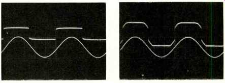
Fig. 1--Operation of limiter at low signal level. Upper trace is 1KHz input
signal at 50 mV/cm; bottom is limiter output at 2 V/cm; d.c. zero is second
line from bottom. R26 is set for symmetry and time base is 200 µS/cm. Fig.
2--Operation of limiter at high signal level. Upper trace is 1 KHz input
signal at 5 V/cm; bottom is limiter output; same scale as Fig. 1. R26 is
unchanged from Fig. 1, as is time base.
Things start to get interesting when next you fire up the timer circuits. This operation demands some care. Set S4 for the 1-10 microsecond range and rotate Rt 1 to minimum resistance. Insert IC 5 and check for a negative pulse at IC 5 pin 6. Vary Rt 1 from MIN to MAX and verify a timing range from slightly under 10 microseconds to slightly over 100 microseconds. A similar check can be made of the remaining ranges, progressing upwards in time until the longest range is reached. If a range should fall short of its maximum, pad Ct 1 with an additional capacitor until the spread is reached. There should be more than a 10-1 range with overlap between adjacent ranges of S4. When the pulse length of IC5 exceeds the period of the input frequency (1 millisecond in this case), it will begin to "drop" input pulses. Check to see that this is in fact being done and the pulse width is stable up to and after the point where it drops the second trigger pulse at pin 1.
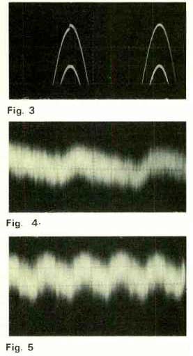
Fig. 3--Operation of offset control R8. Upper trace is correct setting with
switching occurring at negative peak, OFF level equals 100% (or equal to
ON level). Lower trace shows incorrect setting of R8 with d.c. level of
OFF level lower than ON level. Scales are 1 V/cm vertical and 20 µS/cm
horizontal, input 10 KHz. Fig. 4--Residual hum and noise of tone burst
generator with input shorted. Scales are 1 mV/cm vertical, 2 mS/cm horizontal.
Fig. 5--Residual crosstalk of generator with gate OFF by switching to EXT
with no EXT input. Signal input is 10 V p-p at 1 KHz. Scales are 1 mV/cm
vertical, 500 AS /cm horizontal.
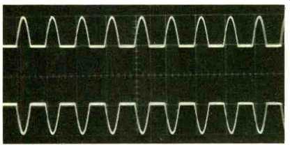
Fig. 6--Operation of COUNTED-DIRECT mode with 1 KHz input at 10 V p-p. Upper
trace is coarse phase 0 degrees with R26 centered, d.c. zero is second line
from top. Lower trace is coarse phase 180 degrees with R26 centered, d.c.
zero is second line from bottom. Scales are 5 V/cm vertical, 1 mS/cm horizontal.
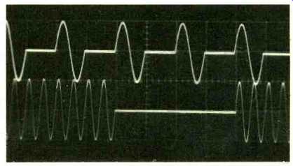
Fig. 7--Operation of COUNTED-DIVIDE by 2 and 16 with input 1 KHz at 10 V
p-p. Upper trace is 2 (1 ON, 1 OFF) at 1 mS/cm, d.c. zero second line from
top. Lower trace is 16 (8 ON, 8 OFF) at 2 mS/cm, d.c. zero second line from
top.
In a similar manner IC6 can be checked out and its timing ranges verified. Set S4 for a range of 1000 is or less and insert IC6. Check for a negative pulse at IC5-3 and 4. The width of this pulse should vary in a manner as was described above for ICS's output. Run through the ranges of S5 and check for overlap and 10-1 range of Rt2. This completes the synchronizer circuit checkout.
At this point you should be able to verify complete synchronizer operation by monitoring SYNC OUTPUT at J3.
In the COUNTED position of S2 you should get a variable frequency square wave from ' to 1/16 the input frequency as S3 is rotated from 2 to 4, 8, and 16. In the DIRECT position of S3 you should get a "squared up" version of the input signal with phase adjustable by S 1 and R26. In the TIMED position of S2 you should get the variable pulse length of IC5 effected by S4 and Rt1, while S5 and Rt2 will determine the spacing between pulses.
Now we are ready to check the switch for operation. If everything is wired correctly you may see a gated tone burst at J4 already, but it may not yet make proper sense. Rotate R5 (on level) to MINIMUM (max counterclockwise) and set R8 to the center of its range. With a high gain d.c. coupled scope or the lowest range on your VTVM or VOM, set R3 for zero volts d.c. at IC2 pin 2. This biases IC2 for zero input d.c. offset. Then set R15 for a output d.c. baseline of zero volts observed at J4. Set Mode switch S2 to COUNTED and Count Ratio S3 to 2.
With Override switch S6 in NORMAL you should see a gated tone burst with ON level equal to the INPUT level and OFF level ZERO. Depress S6 down momentarily and the OFF period should fill in. The generator is now working and all that now remains is to set R8 for minimum offset. Bring up OFF level control R5 until the p-p level during the OFF level is equal to the ON p-p level.
You can reduce input level to 1 p-p or less and expand scope sensitivity to see this effectively. Switch to the timed mode and set S4 and Rt 1 to switch at a peak of the sine wave. You will probably see an offset between the peaks like Fig. 3, bottom. Rotate R8 until this offset is nulled, as in the waveform directly above. Now you should be able to operate R5 from MIN to MAX and gradually "fill in" the OFF period of the burst. At the maximum position of R5 the OFF level may be slightly over or slightly shy of the ON level. If it is short you can trim RE6 to a slightly lower value to make up the difference. Once this is done you should not have to adjust R8 or R3 again.
Now rotate R15 from MIN to MAX and check for +5 volts of d.c. baseline shift. Reset R15 for zero volts baseline and adjust the input for 10 volts peak output ON level. Load output with 500 ohms and check that waveform is undistorted. By either raising the input further or shifting R15 plus or minus you should see the Q4-Q5 output current limit at slightly above ±5 volts.
This completes the setup and checkout, and the generator will now perform as per the specification objectives listed in Part I.
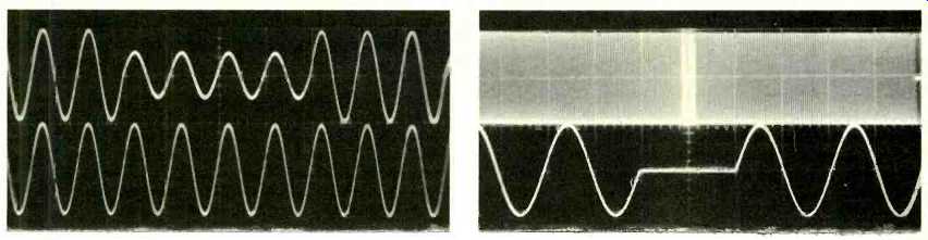
Fig. 8--Operation of TIMED mode with override. Input is 10 V pip at 10 KHz.
Upper trace is 3 cycles ON, 4 cycles OFF, 50% OFF level. D.C. zero is second
line from top. Lower trace is same input signal but overridden with S6. D.C.
zero is second line from bottom. Scales are 5 V/cm vertical, 100 µS/cm horizontal
both traces. Fig. 9--Operation of TIMED mode with high duty cycles. Input
is 10 V p-p at 10 KHz, timing set for 99 cycles ON and 1 OFF. Upper trace
is gated output at 2 mS/cm horizontal sweep with OFF time intensified. Lower
trace is the intensified portion expanded to 50 µS/cm to show 1 cycle of
OFF time. Vertical scale factor for both traces is 5 V/cm.
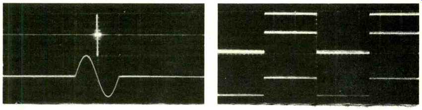
Fig. 10--Operation
of TIMED mode with low duty cycle. Input 10 V p-p at 10 KHz. Timing set
for 1 cycle ON, 99 OFF. Upper trace is gated output at 2 mS/cm horizontal
sweep with ON time intensified. Lower trace is intensified portion expanded
to 50 µS/cm to show 1 cycle of ON time. Vertical scale factor is 5 V /cm
for both traces. Fig. 11--Using the tone burst generator as a variable frequency,
variable duty cycle oscillator with logic level and variable output. Mode
control set to TIMED, S4 and S5 on 1-10 mS ranges, Rt1 and Rt2 adjusted for
5 mS. IC6 pin 8 jumper to J1 input. Upper trace is double exposure of J4
output at two different settings on OFF level control. Vertical scale is
2V/cm and d.c. zero is center of graticule. Bottom is J3 output (sync) at
5 V/cm. Horizontal scale is 2 mS/cm for both.
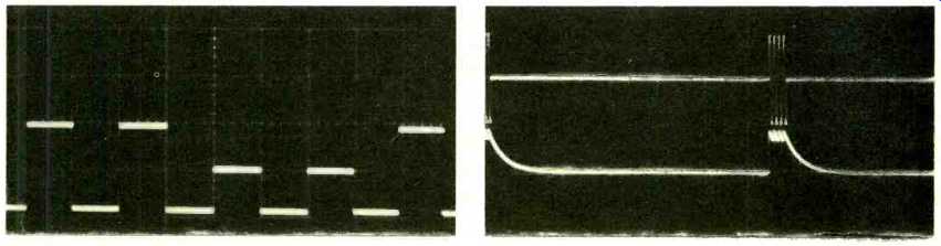
Fig. 12--Use as an oscillator with variable COUNT and variable OFF level
in alternate group periods. Oscillation frequency as set in Fig. 11, but
output switching done in COUNT Mode 4. ON for two periods, and OFF for two
periods. OFF level is set to 50%, d.c. zero is bottom of graticule. Vertical
scale is 2 V/cm, horizontal 5 mS/cm. Fig. 13--Tone burst with low duty cycle
used to check a half wave rectifier time constant. Four cycles of 10 KHz
space 6.5 mS. Scales are 5 V/cm vertical and 1 mS/cm horizontal for both
scales. D.c. zeros are second lines from both top and bottom respectively.
Top is input to rectifier, bottom is output.
Operation
Now that you have your tone burst generator operating, you will quickly become fascinated by the wide variety of waveforms it can produce. Spend a few minutes familiarizing yourself with the operation of the controls. Run each control in each mode through its range and observe the effect on the output waveform as you change the settings. A few examples illustrating operation are shown in the waveform photos. These you should be able to reproduce easily. All were taken with a Tektronix 545A scope with a type W plug-in.
Uses of the Tone Burst Generator
Much has been written on the various uses of tone burst generators. Its main flexibility is in the fact that it is a bridge between steady state sinusoidal tests and pulse or rectangular wave tests. It produces a controlled transient waveform of wide usefulness in loudspeaker tests, amplifier music power checks, acoustic work, sonar work, testing of filters and tuned networks, rectifier response, meter ballistics, and many others. These and other applications are well covered by Skilling (2) (3) (4) in the General Radio literature, and more recently Annes (6) has illustrated practical uses of the device. All of these uses are well served by this version also, as well as some more which will now be described.
The classic portrait of a tone burst is a gated sinusoid. Although this is indeed a tone burst, the association of only the sinusoid with burst testing is a severe mental limitation of the techniques available. Any periodic waveform can be gated with this tone burst generator-square, triangular, pulse, saw-tooth-you name it. As a pulse gate you can use the device as a variable divider of ratios up to 100 with excellent stability. You'll get a divided logic compatible output from the J3 sync output and a variable level output from the main output with the added feature of variable d.c. offset.
The output of this unit is intentionally designed to drive IC logic stages as well as linear amplifiers. The d.c. baseline offset may be used as one limit of logic level and the OFF level control as the other. In this manner logic stages can be checked dynamically with no further equipment. The current rating of ± 10 mA allows several stages to be driven without distortion of the voltage waveform. And the fact that there is complete control over the baseline, level and polarity will allow it to interface with most popular logic families such as DTL, TTL, RTL and ECL. Thus the device can be used as variable period digital word generator with the ability to generate a wide variety of output pulse shapes. An additional feature beyond the division capability is the variable OFF level. By using the variability of the OFF level in conjunction with the baseline control, you can simultaneously test the ON and OFF levels of a logic stage for instance.
The flexibility of this instrument goes beyond the division of an input waveform. You can use the timer circuits as a variable frequency and duty cycle oscillator. To do this it is necessary to jumper IC6 pin 8 to the input JI. This closes an oscillating loop through IC1, IC3 and IC4 to IC5 and IC6. The ON and OFF timers IC5 and IC6 serve as independently variable timers which comprise the two portions of an oscillating cycle. An example of this operation is shown in Fig. 11. Here the times of IC5 and IC6 are set for equal lengths of 5 mS, thus setting up a symmetrical 100 HZ square wave. In Fig. 3 both logic level and variable outputs are shown.
The variable output occurs from the action of the square wave gating itself ON and OFF, thus OFF level control R5 serves as a linear gain control. Since there are no limitations on duty cycle on the timers, you can generate pulse or square waveforms over the entire range of IC5 and IC6 timing circuits.
A variation on this is to set up a basic oscillation with the timer, and switch the output to COUNTED. This will give an alternate pattern of ON-OFF levels.
The number pulses in a group are determined by the Count Ratio, and the OFF level set by R5. An example of this is Fig. 12, which shows the oscillation of Fig. 11 gated by the dividers operating as DIVIDE-BY-FOUR. You may want to add an auxiliary jack on the back connected to IC6 pin 8 to enable this hookup or wire in an extra switch to perform the same function.
Obviously a description of the uses of this tone burst generator could go on and on. But at some point we have to stop and turn the controls over to you. It is probably a safe guess that builders of this generator will discover many more applications. Towards that end we have included a list of background references which should be helpful both in general and for application ideas. It will be interesting to hear of the diversity of applications which fellow AUDIO readers will find for this tone burst generator. I'm sure we can entice our friendly Editor into sharing the best of them through the Letters column. Have fun with your tone bursts and Happy New Year.
REFERENCES
1. Jung, Walter G.. "The Monolithic Balanced Modulator as a Versatile Audio Switching Element," presented at 41st AES Convention, October 8, 1971. AES preprint *816.
2. Skilling, J.K., "A Generator of AC Transients," General Radio Experimenter, Volume 40, *3; March, 1964.
3. Skilling, J.K., "Generation of Sine-Squared Pulses With the Tone-Burst Generator," General Radio Experimenter, Volume 40, *3; March, 1966.
4. Skilling, J.K., "Testing with Tone Burst Signals," The Electronic Engineer, December, 1966. General Radio Reprint 130.
5. Kelly, Stanley, "Design of a Tone Burst Generator," Journal of the Audio Engineering Society, Volume 18, *4; August, 1970.
6. Annes, Tom, "14 Ways to Use R-E's Tone Burst Generator," Radio Electronics, Volume 42, *8; August, 1971.
(adapted from Audio magazine, Jan. 1972)
= = = =