Radio communication plays an important part in our lives, and this has never been truer than today when we find ourselves surrounded by radio and television receivers. Most of us tend to think of the world of radio communications as centering around radio and television broadcasting, but there are many other types of communications which employ similar radio frequency transmitters. These are called point-to-point communications systems and are used by school systems (via microwave TV), police and fire departments, and ship-to-shore communications, along with the growing class of hobby communications.
There are two classes of hobby communications; one is known as citizen's radio service or citizen's band (CB), and the other is amateur radio service. As more people take advantage of the ability to communicate without wires, it is important to note that more and more sources of radio frequency energy are being constructed and put into service. Because most of these communications cannot be received on conventional AM/FM receivers, they go relatively unnoticed, but when something goes wrong and we do notice them, we call them interference, a situation that has become all too frequent of late.
Within all our high fidelity equipment, there are common elements which comprise a radio receiver. We have tubes and transistors which amplify tiny signals, and these same tubes and transistors can also rectify these signals, that is convert them in pulsating d.c. to make the radio frequency signals into audio frequency signals which then pass through the various stages of the high fidelity system. At times our hi fi will pick up and amplify signals not intended for it, and the purpose of this article is to discuss the sources of such interference and how to combat them.
Sometimes the source of the interference is unclear; all the listener knows is that some peculiar sound that he doesn't want to hear is being produced by his music system. It may sound as though someone was speaking like Donald Duck but, in reality, the amplifier in the system was detecting radio frequency energy in the form of a single sideband, suppressed carrier transmission, not found on conventional AM/FM equipment.
These signals cannot be truly understood since one of the components which makes up the conventional AM signal is not present.
One common type of interference is from the audio portion of the television broadcast, since stereo amplifiers can receive television signals under the right conditions. Sometimes the video portion is detected and comes out of the loudspeaker sounding something like a 60 Hz hum whose character is constantly changing.
CB Interference
Another common source of radio frequency interference to audio equipment is produced by the radio hobbyist using radio frequency transmitting equipment in his home in a residential area. Of the two classes of radio hobbyists referred to earlier, the most numerous are citizen's radio service. These operators, by law at least, are limited to a power input of five watts. However, when signals are transmitted from locations not too far from yours, the chances are very good that your audio equipment will receive and detect them.
To make matters worse, many of the operators use their CB radio in an illegal manner. A license issued by the Federal Government is required to operate this radio service, but unfortunately (in this country at least) no proof of license is required by dealers when people buy CB equipment. And since people begin operating without a license, the temptation to carry things one step further quickly arises--i.e., linear amplifiers. When this is connected between the CB radio and its antenna, the power obtained is far in excess of the legal five-watt limit, and a 100 to 1500 watts is not uncommon. If you are located in the vicinity of such a high-powered station, interference to your audio equipment is almost unavoidable.
The legally licensed CB user is required to use his assigned call letters.
The illegal operator, not having such call letters, doesn't use them. Furthermore, he won't use his correct name, instead substituting colorful appellations or "handles" such as "The Boston Eagle," "Big Rabbit," "The Bartender's Wife," etc. to separate him from other illegal operators.
It's a shame that this situation has gotten so completely out of hand, since CB radio would enable the average citizen to use a portion of the crowded radio frequency spectrum for his personal or business communications without having to pass difficult examinations or spend huge amounts of money on radio equipment--indeed an excellent and valid concept. Any motorist stranded on the road but equipped with CB radio will tell you the value of this service.
Yet another type of interference to audio equipment is produced by the amateur radio (ham) operator. Again, because this is a hobby, such operators are often found in residential areas. An operator who uses this particular class of radio service must be licensed to do so by the federal government. In order to obtain even the simplest class of license, the ham operator must pass a relatively difficult examination which demonstrates proficiency with International Morse code, the technical aspects of radio transmitting and receiving equipment, and government regulations which must be observed by users of this class of radio communication.
All too often, the illegally operating CBer is mistaken for the legitimate ham operator. For this reason, amateur radio service as a whole often receives an undeserved bad name. In general, the ham operator, like the audio enthusiast, is very much concerned with both the harmonic and intermodulation distortion of his equipment. And when the ham operator has adjusted his transmitter to have a minimum of harmonic and intermodulation distortion for him, the chances are that his transmitter will produce less interference than one which has not been properly adjusted.
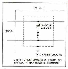
Fig. 1-Series resonant antenna trap with resonance at interfering signal
frequency.
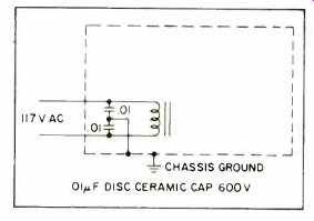
Fig. 2-Power line bypassing. If the frequency of interference is above 50
MHz, the values may be reduced to avoid self-inductance.
Wideband Disruption
It is also worth noting that any equipment designed to receive radio signals can also be subject to interference from them, and television receivers are perhaps the most notable examples. Because of the wide bandwidth required for the reception of video information, it is economically difficult to design front-end input circuitry which will reject the strong signals produced by nearby radio transmitters in the frequency range of 20 to 200 MHz.
High quality FM receivers are less susceptible to this kind of interference since their front ends are generally designed to have a narrower bandwidth than it is possible to use in television receivers. Even so, a strong local transmitter can degrade performance on an FM set.
Much of the interference to television receivers is produced by transmitters operating at frequencies considerably lower than the lowest of television channels, Channel 2, which has a lower band edge of about 54 MHz. The undesired signals enter the set and simply overload the circuitry.
To eliminate these lower frequency signals, all that is required, in most cases, is the use of a high-pass filter so designed that it will either eliminate or greatly weaken the signals falling below Channel 2.
Because not all TV set owners are affected, manufacturers do not usually include such filters as part of their designs. However, some manufacturers do make such filters available at nominal cost. In addition, some high-pass filters are available from other sources, and these include the R.L. Drake Model TV-300-HP and Finco's Model 3013.
Television receivers may also be affected by FM stations which transmit in a portion of the spectrum which lies just above Channel 6, the standard 88 to 108 MHz band covered by FM. Again, filters designed to eliminate this source of interference are available. Some makes and models of FM band reject filters are the JFD Model TR-FM, Drake Model 300 FMT, Finco Model 3006, and Drake Model 300 FMS, the last of which is useful for interference from stations in the low end of the FM band where reception of Channel 6 is desired. The first three filters will cause a 10-dB reduction of signal strength from Channel 6, so if you live in a fringe area, this signal loss may not be tolerable.
FM stations transmit on a frequency band which falls between the higher edge of Channel 6 and the lower edge of Channel 7. There are other radio sources which also share space within these boundaries, the public service station at 154 MHz, for example.
Should a signal of this kind start to degrade television reception, it can be eliminated by the use of a series-resonant filter shown in Fig. 1. This trap should be mounted in a metal container which is grounded to the chassis of the TV set. The input leads of the trap should be connected directly across the antenna terminals of the tuner itself where practical. By making the connections in this manner, rather than to the regular antenna terminals on the rear of the set, this eliminates signal pick-up by the leads which interconnect the binding posts to the actual tuner. In order to make such a trap successful, it is necessary to know the frequency of the interfering signal and tune the trap to that frequency.
FM sets, because of their "tighter" front ends, are less subject to interference from off-frequency radio transmitters. However, such interference [... missing]
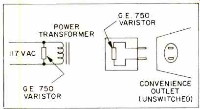
Fig. 4-Interference suppression on the a.c. power line.
Cable Connectors
Cables connecting the hi-fi system components can also pick up radio frequency signals. Such cables can be shielded against stray 60 Hz hum fields, but the shield is not always effective against r.f. interference. If the frequency of the interfering station is over 100 MHz, you might try Fig. 3D. (The ferrite beads can be salvaged from a discarded television set of recent design.) Where the frequency of the interference is low, a conventional r.f. choke can be used. Every attempt should be made to keep inter connecting cables as short as possible.
In no event should their length be a multiple of a quarter wave of the signal causing the interference.
The interconnecting wire between the speaker and amplifier can also act as an antenna, since the signals can find their way back into some early stage of the amplifier through the feedback loop. Directly connected to the "hot" speaker output on the amplifier is a capacitor whose other lead terminates at some early point in the amplifier, and this provides an easy path for the entry of r.f. energy, which will be rectified and amplified through the remaining stages of the amplifier and heard through the loudspeakers. Although solid-state units exhibit more of a tendency to rectify signals than vacuum tube units, the problems exist in both and the cures are the same. Take some of the excess speaker wire and wrap it around a transistor radio antenna coil. Long ferrite rods are best and should be used near the amplifier chassis. Where this is not sufficiently effective, Fig. 3E should do the trick. This circuit may have some strange aspects, as the capacitor is put from the ground side of the speaker terminal back to ground.
This is done because, while the ground is a good one for audio frequencies, it is not a good r.f. return.
The ground systems for audio amplifiers are laid out to minimize hum and noise so the input connectors are not mounted directly to the chassis. This is the reasoning behind both Figs. 3C and 3E. Figure 3C has been introduced because sometimes interference is picked up by the shield of an interconnecting cable and enters the amplifier because of inadequate r.f. grounding. The small bypass shown here will provide the r.f. grounding necessary, yet not disturb the audio grounding required for good hum reduction.
Often, no matter how we try, the interference still persists. To overcome this, install bypasses to short out the rectifying junctions of transistors, but only for r.f. See Fig. 3A; note that Fig. 3B is the same arrangement; for vacuum tubes, and because of the higher impedances of this circuit, the values shown in 3B are much lower than 3A. To minimize performance degradation, bypassing should be performed on as few stages as possible.
Interference is generally heard on both channels of a sound system, but you should only modify one channel at first and then compare the sound on that channel with the unmodified channels to hear if any degradation has occurred. It may be possible to reduce the values of bypassing and still have sufficient interference rejection.
Once you know that the modified channel is working well, you can modify the other channel with equally good results, both in terms of r.f.i. suppression and maintaining a high level of audio quality.
At no time in the discussion have we alluded to the possibility that the radio transmitter itself was at fault, because in 90 percent of our complaints the deficiencies proved to be within the receiving or audio equipment.
However, where it is suspected that the radio transmitter is at fault, it is a good idea to locate the source of such radio interference and report it directly to the Federal Communications Commission. This report should be sent to the field office nearest you. Some help in this regard may be obtained by writing for FCC Bulletin No. 15 at your nearest field office.
Not all interference in receiving equipment is produced by radio transmitters, as equipment operated on the a.c. power line can often generate interference. This can be eliminated by use of a surge protector, such as the GE MOV-750, installed directly across the power line terminals. This must be done inside the equipment as shown in Fig. 4.
Design Problems
Sometimes the ageing of components within the amplifier will give rise to unwanted sounds from the loudspeaker. Poorly designed AM and FM tuners or receivers may pick up all sorts of undesired sound from the loudspeaker. Poorly designed AM and FM sets may receive all sorts of undesired signals, especially at night.
This can be the result of poor design, especially in regards to front-end selectivity and AGC design.
Where the surge protector does not completely eliminate the problem, bypassing, along the lines of Fig. 3A and 3B, will generally prove effective, but when possible, surge protecting varistors should be placed across the line of the offending equipment. The reason that line interference can be treated in the manner of r.f.i. suppression is that transient pulses produce a wide frequency spectrum, acting as radio transmitters not too different from the old spark wireless of the early radio days.
No article of this kind can hope to list all the causes and cures for radio interference. However, those with an experimental turn of mind should be able to successfully use this information when confronted with the majority of radio interference problems.
Those not sufficiently trained in the field of electronics are encouraged to consult either a service technician or the equipment manufacturer.
Some excellent material has been published by both the U.S. and Canadian governments. You may wish to write for FCC Bulletin Nos. 15, 24, and 25, N.Y.-L34 (.41), and Statement to Television Receiver Owners-41-WB. Canadians may write to the Canadian Department of Communications (DOC) for Circular TRC-19. A
(Source: Audio magazine, Jan. 1977; Joseph Giovanelli)
= = = =