Manufacturer's Specifications:
Frequency Response: Phono, 20 Hz to 20 kHz, ±0.2 dB; high level, 1 Hz to 500 kHz, +0,-1.0 dB. THD: 0.02%, 20 Hz to 20 kHz.
S/N (Unweighted): Phono, 80 dB with "Low" sensitivity setting, 76 dB with "Mid" setting, 72 dB with "High" setting; high level, 90 dB.
Phono Input Sensitivity: "Low" setting, 1.5 mV; "Mid" setting, 0.5 mV; "High" setting, 0.15 mV. Phono Overload Level (for 0.1% THD at 1 kHz): "Low" setting, 180 mV; "Mid" setting, 60 mV; "High" setting, 18 mV. Output Level: Main, 1 V; tape, 0.1 V.
Power Requirements: 120 V a.c., 60 Hz, 20 watts.
Dimensions: 19 in. W x 2 3/4 in. H x 10 in. D (48.3 cm x 7 cm x 25.4 cm).
Weight: 13 lbs. (5.9 kg).
Price: $2,495.
Company Address: c/o Fanfare International, 500 East 77th St., New York, N.Y. 10021.
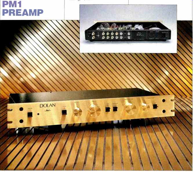
The Dolan company was formed in 1983 by a couple of computer consultants who decided to turn their audio hobby into a business. From what I understand, the PM1 is the only product in their line at present, but an interesting power amplifier that will drive 0.1-ohm loads is in the works and should be out in early 1990. Their preamplifier has a rather striking appearance because of its low, rack-width front panel, which is brushed gold with knobs to match.
The PM1's front panel includes rotary balance and volume controls; switches for power and mute on/off, mono/ stereo mode, tape monitor, and, finally, selection of input, phono input resistance, and phono input capacitance. Rotary switches are used for the input and phono input-resistance selectors.
Located on the rear panel are seven pairs of high-quality Tiffany input and output RCA connectors, a ground binding post, a three-position phono gain switch, two switched outlets, one unswitched outlet, and a combination a.c. power cord socket and line fuse.
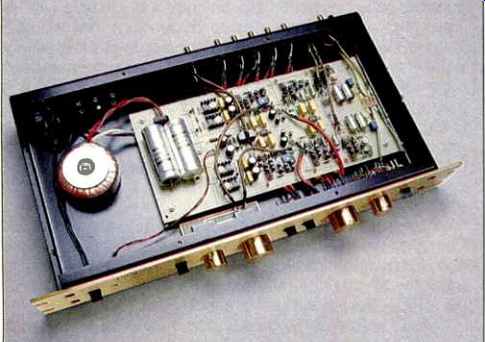
Looking within, we find a single-sided p.c. board taking up about 60% to 70% of the interior space. To the left of this board, as seen from the front, is a 30-VA toroidal power transformer. While most components built with p.c. boards have board-mounted switches and signal jacks, the PMI's jacks and switches are not mounted to the board. Numerous pairs of shielded wires by Straight Wire connect the front panel controls and signal jacks to the board. Of note here is that these shielded wires go right to the point of use on the board rather than to the edge, as is typical. The volume and balance controls have a small p.c. board under them for circuit interconnection because these parts are of the p.c. mount type. Parts and construction quality appear to be of high order.
The chassis is a single sheet of steel, bent up to form the rear, sides, bottom, and front subpanel. The front subpanel and rear panel are further bent over at the top to create a 5/8 inch ledge to mount Pemm nuts for attaching the top cover.
The top cover is a U-shaped piece of steel that covers the sides of the chassis and is screwed into the Pemm nuts in the rear panel and front subpanel and to Pemm nuts in the chassis sides. The assembled unit is rather heavy for a simple preamp and is solid and rigid.
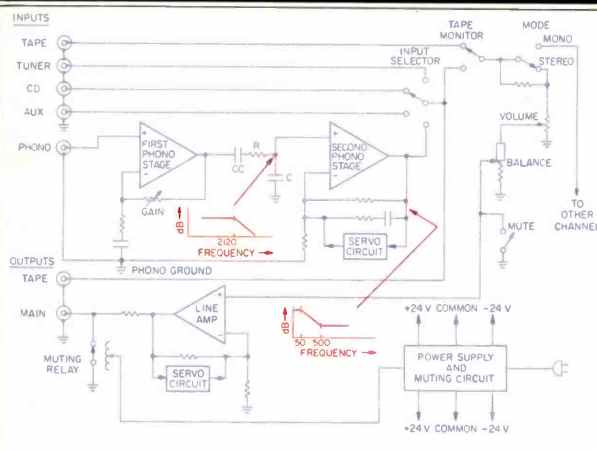
Fig. 1--Circuit topology of the Dolan PM1. Note that RIAA equalization is
split between two networks.
The switchable circuits for phono input loading are not shown.
Circuit Description
I wasn't supplied a schematic diagram for the PM1. However, the owner's manual gives some circuit details, and along with some observation of the insides on my part, I was able to get a pretty good idea of what makes the PM1 tick.
The overall topology of this preamp has three gain blocks per channel, two in the phono preamp, with the third being the line-output amp (Fig. 1). Across the phono inputs (which are also, of course, the inputs to the first phono amp block) are loading networks controlled by two front-panel switches.
One is a rotary switch selecting input resistances of 10, 30, 100, 300, and 1,000 ohms and 47 kilohms; the other, a three-position toggle, adds shunt input capacitance of 0, 150, or 390 pF. The phono preamp's first gain block has flat frequency response and a choice of three gain levels, selected by a switch next to the phono input jacks on the rear panel. The output of this block is capacitor-coupled to an RC network (a resistor in series and a capacitor in shunt) that performs the RIAA equalization's 2,120-Hz roll-off. This RC network then feeds the input of the second phono circuit block.
This second block adds more gain and provides the RIAA equalization's bass boost from 500 to 50 Hz in the feedback loop around this gain block. A servo circuit around this block keeps its output d.c. offset low, so that output coupling capacitors won't be required between this block and the tape-out jacks and selector switch. The servo is said to have a low-frequency cutoff of 0.5 Hz, with a slope of 6 dB per octave; this means the low-frequency cutoff of the second phono stage and the line stage is also 0.5 Hz.
The output of the phono preamp, along with three of the four high-level inputs, is applied to the selector switch.
Output of the selector switch feeds the tape output jack and one input terminal of the tape monitor switch; the tape input jack feeds the switch's other terminal. Emerging from the tape monitor switch, the signal next encounters the stereo/ mono mode switch, a double-pole/double-throw toggle. In stereo mode, this switch just passes the signal through. In the mono mode, the signal-source channels are tied directly together, and series resistors are inserted in the signal path for each channel-presumably to reduce the level of the mono sum. In my opinion, this is not the way to do it, as it shorts the two channels of the selected source together, which could cause distortion with strong out-of-phase information. Perhaps there was a wiring mistake in the sample I was sent for review.
Next come the volume and balance controls. The volume control is a 50-kilohm, log-taper unit. The balance control is a silvered, 25-kilohm unit-that is, its wiper track is of low resistance from one end to the center, with the 25-kilohm resistance between the center and the other end. The balance control's wiper feeds the input of the line amplifier.
Also, at this circuit point, the front-panel mute switch shorts the signal to ground when in the mute position. Another result of this topology is that, in stereo mode, the selected source gets shorted to ground if the front-panel muting switch is engaged when the volume control is full up. This is not a likely condition, however, as the volume control is rarely set to its full-clockwise position.
The signal circuitry of each of the gain blocks is all discrete, with the exception of IC op-amps in the servo circuit. At the start of each gain block is a differential amplifier that is resistively loaded and direct-coupled to another differential amp that forms the block's second stage. This stage is connected in a cascode arrangement and terminates in a current-turnaround circuit whose output signal to ground is the sum of both differential phases. This signal then drives complementary emitter followers that are biased for Class-A operation and produce the final output signal from a low output impedance.
The first stage of the phono circuit uses a low-noise LM394 monolithic transistor pair. This device is an NPN type, and presumably the other gain blocks start out with input devices of N-channel polarity. This would mean that the second stage's differential amp and cascode devices would be of P polarity and probably bipolar, and the current-turnaround devices would be N polarity. The line amp is said to use FET devices, so an input coupling capacitor to that gain block is not needed. In all three of these blocks, the input signal is applied to the noninverting input of the input differential pair and the feedback is applied to the inverting input, in typical op-amp circuit topology.
The power supply in the PM1 starts out with a 30-VA toroidal power transformer feeding a bridge rectifier and capacitor input filters to produce an unregulated positive and negative 32.5-V d.c. supply across two 1,500-µF, 50-V capacitors. Two positive and two negative four-terminal TO 220-sized IC regulators of a variety I'm not familiar with feed the two amplifier circuit channels with ±24 V. From what I could see, these regulated voltages feed all three gain blocks of each channel directly, with no resistive decoupling along the way. There are small, apparently monolithic (and hopefully Mylar) bypass capacitors on the supply lines at the local site of each gain block.
A time-delay circuit mutes the output for a suitable period at turn-on, so that circuit-settling surges won't emerge from the main outputs. The tape monitor outputs are not so muted. A normally closed pair of contacts in the muting relay directly shorts the main output until the time-delay circuit energizes the coil and thus unshorts the outputs.
Upon turn-off, the relay immediately shorts again, thus preventing turn-off thumps from coming through.
Measurements
Focusing on the output line section first, output resistance was measured and found to be about 660 ohms at the main outputs. Since this unit has no buffer resistors in series with the tape-out jacks, the output impedance looking back into these jacks is that of the selected source. The impedance of the line inputs is about 50 kilohms-that of the volume control's value when the volume control is turned down. This input impedance decreases to about 13.5 kilohms at full volume, due to the 25-kilohm balance control's becoming in parallel with the 50 kilohms of the volume control and some input resistance in the line amp also coming in parallel. The theoretical value would be 16.7 kilohms if no other resistance was in shunt. The input impedance will stay above about 45 kilohms until the volume control is taken past half rotation. In my use of the unit, I generally set the volume control below that point for the weakest source, which was phono in medium gain mode.
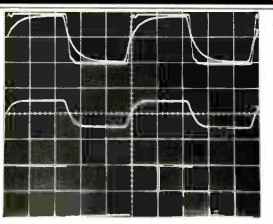
Fig. 2--Line-section square-wave response.
Overlapped traces (top) show 100 kHz into instrument and IHF loads; middle trace shows 100 kHz into instrument load, with volume control turned down 6 dB; bottom trace is 20 Hz into instrument or IHF load.
(Scales: Vertical, 5 V/div.; horizontal, 2 µS/div. for 100 kHz, 100 mS/div. for 20 Hz.)
Volume control tracking was found to be within 0.2 dB from the control's highest setting down to the second detent from full counterclockwise (60 dB). At the next-to-last detent (about -87 dB), the difference between channels was 2.4 dB. This is very good performance.
The d.c. offset of the output amp measured about + 1 mV for the right channel and + 13 mV for the left.
Referred input noise for the line section is shown in Table I. This unit seems to have some kind of ground-loop problem when the volume control is fully clockwise and the inputs are terminated in any low to medium impedance, as the noise was mostly composed of a strong, 60-Hz-based signal with strong, lower odd harmonics. This is evident in Table I in the cases where the volume control is fully clockwise and the inputs are terminated, for those measurement bandwidths that don't attenuate the lower harmonics of the 60-Hz line frequency. This hum is just audible at the speakers in my setup, with the line inputs terminated and the volume fully up. With the volume clockwise and the inputs open-circuited, this waveform went away and full-bandwidth noise was much lower. In the rest of the spectrum (above 400 Hz), noise is satisfactorily low. Interestingly, the IHF S/N ratio was not affected by this full-volume 60-Hz noise. This is because the IHF measurement, which is A-weighted and referenced to 500 mV, is made with the volume control turned down about 20 dB, to the point where 500 mV input produces 500 mV out.
Crosstalk between channels was measured for the line section and was found to be quite symmetrical with respect to direction. It was better than-80 dB up to about 3 kHz, decreasing to -70 dB at 10 kHz, -64 dB at 20 kHz, and 56 dB at 50 kHz. At 10 kHz, rotating the balance control toward the driven channel increased the crosstalk to about 63 dB, and with the balance control centered and the volume control turned down to worst-case crosstalk, the amount increased from -70 to -64 dB. This is quite good performance in this area.
THD + N was less than 0.01% from 20 Hz to 20 kHz at 4 V rms output or less, with instrument or IHF loading. Harmonic distortion was dominantly second order. The distortion level stayed reasonably constant with frequency, but the distortion products got a bit more complex from 10 to 20 kHz.
Clipping, with either instrument or IHF loading, occurred at about 13 to 14 V rms. The unit drives 600 ohms quite nicely, with no low-frequency roll-off, as there is no output coupling capacitor.
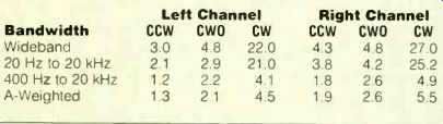
Table I--Line-section noise levels (in µV), referred to input, vs. bandwidth
for counterclockwise volume setting with 1kilohm input termination (CCW),
clockwise volume setting with inputs open-circuited (CWO), and clockwise
with inputs terminated by 1 kilohm (CW). The IHF S/N ratio was 88.0 dB for
the left channel and 88.5 dB for the right.
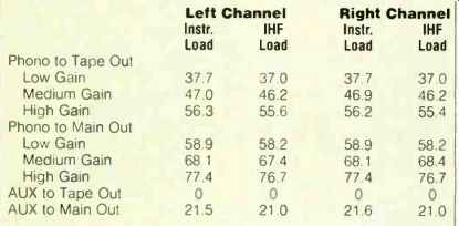
Table IIA--Gain (in dB) with instrument and IHF loads, at all three gain
settings.
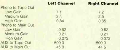
Table IIB -- IHF sensitivity (in mV), at all three gain settings.
Output amplifier rise- and fall-times for ±5 V out, volume at maximum, and instrument loading were about ±0.3 µS, with some ringing evident. Under the same conditions but for IHF loading, the rise- and fall-times were ± 1.6 µS. With instrument loading and the volume reduced to-6 dB, rise and fall-times lengthened to ±1 µS. Slewing started to occur above 10 V peak to peak and was worse on the positive-going transition. Figure 2 shows 'scope photos of output amp square-wave performance. The top trace is for 100 kHz at an output level of 10 V peak to peak, with both instrument and IHF loading. The middle trace shows the same signal, with instrument loading but with the volume control turned down 6 dB from maximum. The bottom trace is for 20 Hz and is the same with either instrument or IHF loading. A slight amount of tilt is evident here, due to the servo's low-frequency corner.
Turning to the phono section, gain and sensitivity measurements are shown in Table II. Table III shows referred input noise as a function of phono gain setting for a variety of bandwidths and input terminations; IHF S/N ratios are also listed in this Table. Noise performance of the phono section is pretty good, and noise is unlikely to be a problem except when using MC cartridges, of extremely low output, without a step-up transformer.
Crosstalk between channels was measured for medium and high gain settings, with the undriven channel terminated by 100 ohms. Results were about the same for both gain settings and were quite symmetrical with respect to direction. Crosstalk was down more than 80 dB at frequencies up to about 10 kHz, increasing to about 72 dB at 20 kHz. In the low gain mode, treated as an MM input and terminated in the dummy IHF MM load, crosstalk was down more than 80 dB at frequencies up to 1 kHz; crosstalk peaked at 10 kHz, where it was about 50 dB down.
Phono overload versus frequency is shown in Table IV for low and high gain settings. The left channel is shown here; both channels were very close in their measurements. The output level at the overload point is quite constant with frequency, which means the input acceptance is effectively constant with frequency as well-that's very close to ideal.
A bit of clarification on that: Both MM and MC cartridges are velocity-responsive. When playing an LP of test signals from 20 Hz to 20 kHz, made with RIAA record equalization, the cartridge's output will rise with frequency, and that rise will be the inverse of the RIAA playback EQ curve. Now imagine a test disc that would drive the cartridge so hard that it made the phono preamp circuit just begin to clip at 1 kHz, and that it put out correspondingly high levels at all frequencies from 20 Hz to 20 kHz. (In actuality, no such disc could be cut, and no cartridge could track it.) A phono preamp with ideal signal acceptance would just begin to clip at all the frequencies from 20 Hz to 20 kHz.
Figure 3 shows RIAA equalization error versus frequency.
The curves shown are for the medium gain setting; the response curves for the low and high gain positions were virtually identical. IHF loading didn't change the curve's shape, just its level. Of note here is the very close channel match and the general roll-off shelf at the low end.
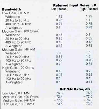
Table III--Phono-section noise, referred to input, and IHF S/N ratios vs.
gain setting and source impedance.
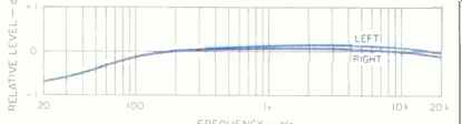
Fig. 3--RIAA equalization error at medium gain setting, with instrument
load on output and 47-kilohm resistive load on input.
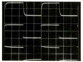
Fig. 4--Response to pre equalized square waves through phono input for,
top to bottom, 10 kHz, 1 kHz, and 40 Hz. (Scales: Vertical, 0.5 V/div.; horizontal,
20 µS/div. for 10 kHz, 200 µS/div. for 1 kHz, 5 mS/div. for 40 Hz.)

Fig. 5--Results of deliberate high-frequency overload from 1-kHz square
waves at four different input levels.
Note the symmetrical clipping; see text.
(Scales: Vertical, 2 V/div.; horizontal, 200 µS/div.)
Oscilloscope photos of pre-equalized square-wave signals going through the phono preamp are shown in Fig. 4.
From top to bottom, the test frequencies are 10 kHz, 1 kHz, and 40 Hz. The 10and 1-kHz waveforms look really good, and the effects of the low-frequency roll-off shelf in the frequency response can be seen in the 40-Hz square wave.
The traces shown are for instrument loading; IHF loading didn't change their shape, though it did change their level slightly.
Figure 5 shows the result of feeding in a 1-kHz pre-equalized square wave whose high-frequency content is not band-limited and then increasing this signal's amplitude at the input. All phono preamps ultimately overload when out of-band high frequencies are applied in this way. As Fig. 5 shows, when the PM1 overloads, the resulting compression is symmetrical, which is desirable circuit behavior.
I also tried this test with the low gain setting-a largely academic test, since the resulting signal levels would be unlikely to occur with actual cartridges-and something interesting happened: The preamp latched up and went to +20 V d.c. output in one channel and-20 V in the other! "Oops, there goes this circuit," I thought. "I won't be able to listen to it." But after some dispirited tweaking of the gain switch and the input signal level, lo and behold, the PM1 came back and worked again! Phono-stage harmonic distortion was, as usual, hard to measure without some hum contaminating the results. In the high gain mode, I got about 0.01% THD + N from 20 Hz to 10 kHz, rising to about 0.014% at 20 kHz at an output level of 3 V rms--both good results--with either instrument or IHF loading. The harmonic distortion residue was essentially second-harmonic.
I also measured d.c. offset. At the tape output, with the phono input selected, it was less than 10 mV in either channel.
Use and Listening Tests
Equipment used to evaluate the Dolan PM1 included an Oracle turntable fitted with a Well Tempered arm and Koetsu Black Goldline MC cartridge, a California Audio Labs Tempest II Special Edition CD player, a Nakamichi 250 cassette deck, a Technics 1500 reel-to-reel recorder, a Cook-King reference tube phono preamp, and EAR 519 mono tube power amps driving Siefert Research Magnum III speakers and Stax SR-X/Mk3 electrostatic headphones via an SRD-7 Pro energizer.
First listening with the PM1 was with Compact Discs as a source, using the line section of the unit. Generally, the sound was pretty satisfactory and listenable, but the Dolan had a noticeable tendency toward a slight coarsening of texture and a reduction in depth and delicacy when compared to my reference stepped attenuator used as a system volume control.
Phono reproduction through the PM1 was musical and satisfying. However, my sense that the music was being performed in real space, my sense of that space's size, and the general believability weren't as good as with my reference tube phono preamp and stepped attenuator, and the bass was not as prominent.
Operationally, the unit worked nicely; there were no real surprises. I felt that the selector and the phono resistive loading switches felt a little clunky, with slightly too much play in their shaft bushings.
Summing up, I think the Dolan PM1 is a good preamp that basically serves the music, and I recommend it.
-Bascom H. King
(Source: Audio magazine, Jan. 1990)
= = = =